Table of Contents
Advertisement
Arduino Wireless Communication –
NRF24L01 Tutorial
Dejan Nedelkovski
Arduino Tutorials
36
In this Arduino tutorial we will learn how to make a wireless communication between two
Arduino boards using the NRF24L01 transceiver module. You can watch the following
video or read the written tutorial below.
Overview
For explaining the wireless communication we will make two examples, the first one will be
sending a simple "Hello World" message from one Arduino to another, and in the second
example we will have a bi-directional communication between the Arduino boards, where
using the Joystick at the first Arduino we will control the servo motor at the second
Arduino, and vice versa, using the push button at the second Arduino we will control the
LED at the first Arduino.
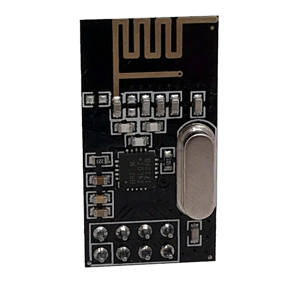
NRF24L01 Transceiver Module
Let's take a closer look at the NRF24L01 transceiver module. It uses the 2.4 GHz band
and it can operate with baud rates from 250 kbps up to 2 Mbps. If used in open space and
with lower baud rate its range can reach up to 100 meters.
Advertisement
Table of Contents

Related Manuals for Arduino NRF24L01


Summary of Contents for Arduino NRF24L01
- Page 1 LED at the first Arduino. NRF24L01 Transceiver Module Let’s take a closer look at the NRF24L01 transceiver module. It uses the 2.4 GHz band and it can operate with baud rates from 250 kbps up to 2 Mbps. If used in open space and...
- Page 2 LED. The operating voltage of the module is from 1.9 to 3.6V, but the good thing is that the other pins tolerate 5V logic, so we can easily connect it to an Arduino without using any logic level converters.
- Page 3 SPI pins of the Arduino, but note that each Arduino board have different SPI pins. The pins CSN and CE can be connected to any digital pin of the Arduino board and they are used for setting the module in standby or active mode, as well as for switching between transmit or command mode.
- Page 4 Here are the two codes for the wireless communication and below is the description of them. Transmitter Code 1./* 2.* Arduino Wireless Communication Tutorial 3.* Example 1 - Transmitter Code 5.* by Dejan Nedelkovski, www.HowToMechatronics.com 7.* Library: TMRh20/RF24, https://github.com/tmrh20/RF24/ 8.*/...
- Page 5 Receiver Code 1./* 2.* Arduino Wireless Communication Tutorial 3.* Example 1 - Receiver Code 5.* by Dejan Nedelkovski, www.HowToMechatronics.com 7.* Library: TMRh20/RF24, https://github.com/tmrh20/RF24/ 8.*/ 9.#include <SPI.h> 10.#include <nRF24L01.h> 11.#include <RF24.h> 12.RF24 radio(7, 8); // CE, CSN 13.const byte address[6] = "00001";...
- Page 6 Description: So we need to include the basic SPI and the newly installed RF24 libraries and create an RF24 object. The two arguments here are the CSN and CE pins. 1.RF24 radio(7, 8); // CE, CSN Next we need to create a byte array which will represent the address, or the so called pipe through which the two modules will communicate.
- Page 7 Arduino Wireless Bi-directional Communication Let’s see the second example, a bi-directional wireless communication between two Arduino boards. Here’s the circuit schematics: You can get the components needed for this example from the links below: • NRF24L01 Transceiver Module………….
- Page 8 • Joystick Module ………………………………. Amazon • Arduino Board ………………………………… Amazon • Servo Motor ……………………………………. Amazon • Pushbutton …………………………………….. Amazon • LED ………………………………………………… Amazon...
- Page 9 Source codes : Here are the two codes and below is the description of them. Transmitter Code 1./* 2.* Arduino Wireless Communication Tutorial 3.* Example 2 - Transmitter Code 5.* by Dejan Nedelkovski, www.HowToMechatronics.com 7.* Library: TMRh20/RF24, https://github.com/tmrh20/RF24/ 8.*/ 9.#include <SPI.h>...
- Page 10 Receiver Code 1./* 2.* Arduino Wireless Communication Tutorial 3.* Example 2 - Receiver Code 5.* by Dejan Nedelkovski, www.HowToMechatronics.com 7.* Library: TMRh20/RF24, https://github.com/tmrh20/RF24/ 8.*/ 9.#include <SPI.h> 10.#include <nRF24L01.h> 11.#include <RF24.h> 12.#include <Servo.h> 13.#define button 4 14.RF24 radio(7, 8); // CE, CSN 15.const byte addresses[][6] = {"00001", "00002"};...
- Page 11 Next, at the transmitter, we set the first Arduino as receiver and with an empty “while” loop we wait for the second Arduino the send data, and that’s the data for the state of the push button whether is pressed or not. If the button is pressed the LED will light up. So these process constantly repeats and both Arduino boards are constantly sending and receiving data.
- Page 12 These amazing low-cost units have a lot of internal complexity but some talented people have written Arduino libraries that make them easy to us. They all use the same pinout as shown in the following diagram, which is a TOP VIEW (Correction!):...
- Page 13 NOTE: These units VCC connection must go to 3.3V not 5.0V, although the Arduino itself may run at 5.0V and the signals will be OK. The NRF24L01+ IC is a 3.3V device, but its I/O pins are 5 V tolerant , which makes it easier to interface to Arduino/YourDuino.
Need help?
Do you have a question about the NRF24L01 and is the answer not in the manual?
Questions and answers