Table of Contents
Advertisement
Quick Links
Advertisement
Table of Contents

Related Manuals for BLAUBERG Valeo


Summary of Contents for BLAUBERG Valeo
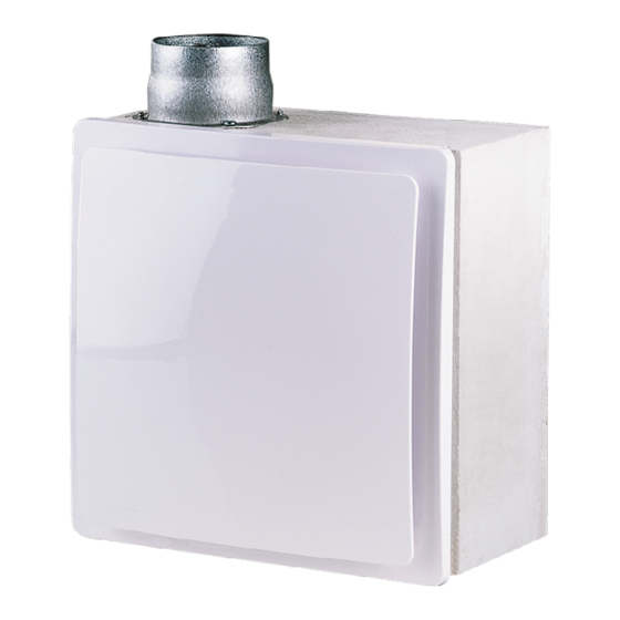
- Page 1 CENTRIFUGAL EXTRACT FAN Valeo USER’S MANUAL...
-
Page 2: Table Of Contents
PURPOSE This user’s manual is a main operating document intended for technical, maintenance, and operating staff. The manual contains information about purpose, technical details, operating principle, design, and installation of the Valeo unit and all its modifications. Technical and maintenance staff must have theoretical and practical training in the field of ventilation systems and should be able to work in accordance with workplace safety rules as well as construction norms and standards applicable in the territory of the country. - Page 3 This unit is not intended for use by persons (including children) with reduced physical, sensory or mental capabilities, or lack of experience and knowledge, unless they have been given supervision or instruction concerning use of the unit by a person responsible for their safety.
- Page 4 Connection to the mains must be made through a disconnecting device, which is integrated into the fixed wiring system in accordance with the wiring rules for design of electrical units, and has a contact separation in all poles that allows for full disconnection under overvoltage category III conditions.
- Page 5 All operations described in this manual must be performed by qualified personnel only, properly trained and qualified to install, make electrical connections and maintain ventilation units. Do not attempt to install the product, connect it to the mains, or perform maintenance yourself. This is unsafe and impossible without special knowledge.
- Page 6 Check the unit for any visible damage of the impeller, the casing, and the grille before starting installation. The casing internals must be free of any foreign objects that can damage the impeller blades. While mounting the unit, avoid compression of the casing! Deformation of the casing may result in motor jam and excessive noise.
- Page 7 The Company reserves the right to modify the technical characteristics, design, or configuration of its products at any time in order to incorporate the latest technological developments. Never touch the unit with wet or damp hands. Never touch the unit when barefoot. BEFORE INSTALLING ADDITIONAL EXTERNAL DEVICES, READ THE RELEVANT USER MANUALS.
-
Page 8: Brief Description
— Valeo — fan assembly designed for installation into a pre-installed BP 80, BF 80. The Valeo-BF, Valeo-BP K meet special fire safety requirements and are designed for preventing smoke fume penetration into the serviced spaces through air ducts in the event of a fire. -
Page 9: Designation Key
DESIGNATION KEY Valeo - BP L Hi-Tech 35/60 K T Additional options T — timer TR – user-adjustable timer I – intermittent operation switch H – humidity sensor (2nd speed) H1 – humidity sensor (1st speed) Fire-safety damper: (for Valeo–E, Valeo–BP) - Page 10 Conventional designation of casings for Valeo fans BFDK 80 Spigot diameter 80 – for series fan Valeo Fire-safety damper: (for BE, BP) _ – not available К – fire-safety damper with fire resistance class EI90 Connection of air ducts from another room: _ –...
-
Page 11: Operation Guidelines
OPERATION GUIDELINES The fan is rated for connection to single-phase AC 220...240 V / 50 Hz power mains. Ingress protection rating against access to hazardous parts and water ingress is IP55. The fan is rated for operation at ambient temperatures ranging from +1°C to +40 °C. The unit is rated as a Class II electrical appliance. - Page 12 Overall and connecting dimensions, the appearance of the products are shown in fig. 1-8. Valeo-E Valeo-E K...
- Page 13 Valeo-BP Valeo-BF...
- Page 14 Valeo-BP K Valeo...
- Page 15 BF 80 BP 80...
-
Page 16: Mounting And Set-Up
1.7. Mount the fan casing together with the scroll and secure it to the mounting surface with self-tapping screws (Fig. 31). 1.8. Complete steps 1.2 to 1.4. in the reverse order. Valeo-E K fan installation steps: 2.1. Mark and drill a hole for the fan outlet spigot according to one of the 4 possible placement variants (Fig. 22-24). - Page 17 These fans are installed in two phases: first the casing installation and then the final installation: • the casing is installed during the shell and core phase. • the final installation, which is performed after the fit-out works, includes the installation of Valeo fan assembly into BP 80, BF 80 casing.
- Page 18 (Fig. 49). If the BP 80, BF 80 housing and the Valeo fan assembly are supplied separately, it is not necessary to disassemble the fan during installation. In everything else, the sequence of installation is preserved.
- Page 19 Installation options Valeo-E...
- Page 20 Installation options Valeo-BP Installation options Valeo-BF...
- Page 21 Installation options for fans with an additional inlet spigot...
- Page 22 Fan placement options relative to walls and ceiling...
- Page 23 Installation steps Valeo-E...
- Page 24 Installation steps Valeo-E K...
- Page 26 Installation steps Valeo-BP, Valeo-BF...
- Page 27 PROTECTIVE CARDBOARD PLATE...
-
Page 28: Connection To Power Mains
– Clamp the wires with the retention clip (Fig. 51); – Assemble the fan: re-install the lid, filter etc.; – Apply supply voltage to the fan. Connection of fans Valeo ... 35/60 Valeo ... 35/100 Valeo ... 35/60/100 Valeo ... 60/100... - Page 29 Wiring diagram of basic fan models Valeo ... 35/60 Valeo ... 35/60/100; Valeo ... 75/100 Valeo ... 35/100 Valeo ... 60/100 Designation key: L – phase N – neutral S – external switch External switch S is used to set the fan to one of the available speeds or disable it manually.
- Page 30 The fan operates at speed 1 when the SB switch is closed or switched off when it is open. The timer circuit board of the Valeo ... 75/100 contains a DIP switch which controls the initial state of the fan.
-
Page 31: Electronics Operation Algorithm
ELECTRONICS OPERATION ALGORITHM T — timer The fan is switched on to the 2nd speed manually by an external switch S1 in parallel with the lighting, with a turn-off delay time of 50 seconds. Once the external switch S1 is returned to the initial position the fan shuts down after a 6 minute timer delay. -
Page 32: Timer And Humidity Sensor Adjustment
TIMER AND HUMIDITY SENSOR ADJUSTMENT DO NOT USE A METAL SCREWDRIVER, KNIFE, ETC. FOR ADJUSTMENT OPERATIONS NOT TO DAMAGE THE CIRCUIT BOARD Attention! The control board circuit is live! Disconnect the fan from power supply prior to any adjustment operations. The fan is supplied with a special plastic screwdriver for adjusting the settings. -
Page 34: Technical Maintenanance
TECHNICAL MAINTENANANCE Technical maintenance includes periodic filter replacement and cleaning the fan surfaces from dust and dirt. The impeller blades require thorough cleaning every 6 months. The filter must be replaced on a need-to-do basis, but at least every 6 months. To replace the filter: •... -
Page 36: Troubleshooting
TROUBLESHOOTING Problem Possible reasons Troubleshooting Make sure the power supply line No power supply. is connected correctly, otherwise When the unit is connected to power mains, the fan does not rotate and troubleshoot the connection error. does not respond to any controls. Internal connection fault. -
Page 37: Manufacturer's Warranty
MANUFACTURER’S WARRANTY The product is in compliance with EU norms and standards on low voltage guidelines and electromagnetic compatibility. We hereby declare that the product complies with the provisions of Electromagnetic Compatibility (EMC) Directive 2014/30/ EU of the European Parliament and of the Council, Low Voltage Directive (LVD) 2014/35/EU of the European Parliament and of the Council and CE-marking Council Directive 93/68/EEC. - Page 38 • Replacement and use of any assemblies, parts and components not approved by the manufacturer. • Unit misuse. • Violation of the unit installation regulations by the user. • Violation of the unit control regulations by the user. • Unit connection to power mains with a voltage different from the one stated in the user's manual. •...
- Page 39 Quality Inspector’s Stamp Sold by (name and stamp of the seller) Manufacture Date Purchase Date...
- Page 40 Valeo ___________________________ Case _____________________________ www.blaubergventilatoren.de B22EN-09...
Need help?
Do you have a question about the Valeo and is the answer not in the manual?
Questions and answers