Advertisement
Advertisement
Table of Contents

Related Manuals for BLAUBERG Turbo 100


Summary of Contents for BLAUBERG Turbo 100
- Page 1 INLINE MIXED-FLOW FANS Turbo USER’S MANUAL...
-
Page 2: Table Of Contents
CONTENTS Delivery set ..........................................6 Brief description ........................................6 Operation guidelines ......................................7 Designation key ........................................8 Installation ..........................................9 Electronics operation algorithm ..................................10 Technical maintenance ......................................12 Storage and transportation regulations ..............................12 Manufacturer’s warranty ....................................13... - Page 3 This user’s manual is a main operating document intended for technical, maintenance, and operating staff. The manual contains information about purpose, technical details, operating principle, design, and installation of the Turbo unit and all its modifications. Technical and maintenance staff must have theoretical and practical training in the field of ventilation systems and should be able to work in accordance with workplace safety rules as well as construction norms and standards applicable in the territory of the country.
- Page 4 READ THE USER’S MANUAL CAREFULLY BEFORE PROCEEDING WITH INSTALLATION WORKS. COMPLIANCE WITH THE MANUAL REQUIREMENTS ENSURES RELIABLE OPERATION AND LONG SERVICE LIFE OF THE UNIT. KEEP THE USER’S MANUAL AVAILABLE AS LONG AS YOU USE THE UNIT. YOU MAY NEED TO REREAD THE INFORMATION ON THE PRODUCT SERVICING.
- Page 5 • Fixed electrical wiring must be equipped with an automatic circuit breaker. • The unit must be connected to power mains through a QF automatic circuit breaker integrated into the fixed wiring system. The gap between the circuit breaker contacts on all poles must be not less than 3 mm. Check the unit for any visible damages of the impeller and the casing before starting installation.
- Page 6 • Do not close or block the intake or extract vents in order to ensure the efficient air flow. • Do not sit on the unit and do not put objects on it. • This appliance is not intended for use by persons (including children) with reduced physical, sensory or mental capabilities, or lack of experience and knowledge, unless they have been given supervision or instruction concerning use of the appliance by a person responsible for their safety.
-
Page 7: Delivery Set
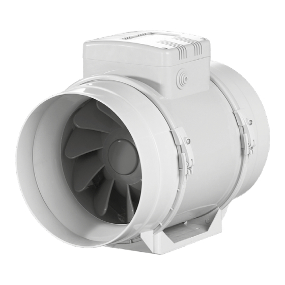
The fan is designed for connection to ø 100, 125, 150, 160, 200, 250 and 315 mm air ducts. The unit is equipped with a two speed motor. Ø D 195,8 226/255* 302,5 Turbo 100 195,6 226/255* 258,5 Turbo 125 220,1... -
Page 8: Operation Guidelines
OPERATION GUIDELINES The fan is rated for connection to single-phase AC 220-240 V/50 Hz or 220 V/60 Hz power mains. The unit is rated for continuous operation. The arrow on the fan casing must match the air direction in the system. Ingress protection rating against access to hazardous parts and water ingress is IPX4. -
Page 9: Designation Key
DESIGNATION KEY Turbo Options: T: timer US: speed switch Gl1: speed controller with an electronic thermostat and a temperature sensor integrated inside an air duct. Temperature-based operation logic G1: speed controller with an electronic thermostat and an outdoor temperature sensor fixed on a 4 m cable. Temperature-based operation logic GTl1: speed controller with an electronic thermostat and an integrated temperature sensor. -
Page 10: Installation
MOUNTING The fan is suitable both for horizontal or vertical mounting on the floor, on the wall or on the ceiling (Fig. 1). The fan can be installed independently or as part of a set with parallel or in-series connection (Fig. 2). Install minimum 1 m long air duct on the intake spigot side in case of horizontal fan mounting or a hood in case of vertical fan mounting. -
Page 11: Electronics Operation Algorithm
CONTROL LOGIC The Turbo XXX T fan starts running after the external switch supplies control signal to the LT input terminal (for example, during turning the light on). After removal of the control signal the fan continues to run within the set time (adjustable with the turn-off delay timer from 2 to 30 minutes). - Page 12 The fan functioning logic may be based on temperature or timer controls: Turbo XXX U(n): the fan switches to the maximum speed as the room air temperature exceeds the set point. As the air temperature drops down 2 °C below the temperature set point or if the initial temperature is below the set point, the fan operates with the set speed.
-
Page 13: Technical Maintenance
TECHNICAL MAINTENANCE The fan surfaces must be regularly cleaned (once in 6 months) from dirt and dust (Fig. 24-30). Disconnect the fan from power mains prior to any maintenance operations. To clean the fan, use a soft cloth or a brush wetted in a mild detergent solution. -
Page 14: Storage And Transportation Regulations
STORAGE AND TRANSPORTATION REGULATIONS • Store the unit in the manufacturer’s original packaging box in a dry closed ventilated premise with temperature range +5...+40 ˚С and relative humidity up to 70 %. • Storage environment must not contain aggressive vapors and chemical mixtures provoking corrosion, insulation, and sealing deformation. - Page 15 BLAUBERG WARRANTY - This warranty is given by Blauberg Australasia Pty Ltd, with an office at U5, 45 Eastern Creek Drive, Eastern Creek, NSW 2766, Australia. Phone 1 300 475504 - From the date of purchase, the original purchaser is entitled to free replacement parts, or a new unit for a...
- Page 16 FOLLOWING THE REGULATIONS STIPULATED HEREIN WILL ENSURE A LONG AND TROUBLE-FREE OPERATION OF THE UNIT. USER’S WARRANTY CLAIMS SHALL BE SUBJECT TO REVIEW ONLY UPON PRESENTATION OF THE UNIT, THE PAYMENT DOCUMENT AND THE USER’S MANUAL WITH THE PURCHASE DATE STAMP.
- Page 17 min 1 m...
- Page 20 Turbo XXX MAX / MIN...
- Page 21 Turbo XXX T MAX / MIN MAX / MIN TERMINAL BLOCK FOR 4 CONTACTS TERMINAL BLOCK FOR 5 CONTACTS...
- Page 23 STOP...
- Page 24 Speed control knob Turbo G1/GT1/GS1 Turbo Gl1/GTl1/GSl1 Thermostat control knob Turbo FR1 Speed control knob...
- Page 27 Quality Inspector’s Stamp Sold by (name and stamp of the seller) Manufacture Date Purchase Date...
- Page 28 Т Turbo www.blaubergventilation.com.au Blauberg_Australasia_B77EN-04...
Need help?
Do you have a question about the Turbo 100 and is the answer not in the manual?
Questions and answers