
Related Manuals for FujiFilm VisualSonics Vevo F2


Summary of Contents for FujiFilm VisualSonics Vevo F2
- Page 1 Vevo F2 Imaging System User Manual Part Number: 53188-04 Revision: 1.0 Last Updated: May 2022...
- Page 2 European Headquarters FUJIFILM VisualSonics T. +31-20-808-2913 Joop Geesinkweg 140 Toll free +800-0751-2020 1114 AB Amsterdam, The Netherlands Manufacturer FUJIFILM SonoSite, Inc. T. 1-425-951-1200 21919 30th Dr. SE F. 1-425-951-1201 Bothell, WA, 9 8021 Toll free 1-888-482-9449 Website: www.visualsonics.com VisualSonics, the VisualSonics logo, Vevo, Vevo MicroMarker and EKV are registered and unregistered trademarks of FUJIFILM SonoSite, Inc. in various jurisdictions. FUJIFILM is a registered trademark of FUJIFILM Corporation in various jurisdictions. Patents: 6,851,392; 6,984,284; 7,052,460; 7,133,713; 7,230,368; 7,255,678; 7,426,904; 7,434,542; 7,740,585; 7,750,536; 7,798,963; 7,808,156; 7,830,069; 7,901,358; 8,078,256; 8,275,449; 8,310,133; 8,316,518; 8,317,714; 8,343,289; 8,708,909; 8,823,246; 8,827,907; 8,847,467; 8,945,014; 9,173,047; 9,184,369; 9,520,119; 9,555,443; 9,445,787; 9,474,498; 9,935,254; 9,997,696; D541,942. Notice of non-liability: FUJIFILM VisualSonics, Inc. is providing the information in this document to you as is with all faults. FUJIFILM VisualSonics, Inc. makes no warranties of any kind (whether express, implied or statutory) with respect to the information contained herein. FUJIFILM VisualSonics, Inc. assumes no liability for damages (whether direct or indirect), caused by errors or omissions, or resulting from the use of this document or the information contained in this document or resulting from the application or use of the product or service described herein. FUJIFILM VisualSonics, Inc. reserves the right to make changes to any information herein without further notice. Copyright © 2022 FUJIFILM VisualSonics, Inc. A ll Rights Reserved. FUJIFILM VisualSonics, Inc. is a subsidiary of FUJIFILM SonoSite, Inc.
-
Page 3: Table Of Contents
Table of Contents Introduction Differences Between the Vevo F2 and Vevo F2 LT Document Conventions System Overview Vevo F2 Imaging System Image Display Control Panel Basic Touchscreen Actions Onscreen Keyboard System Startup To Turn On the Laser Cart Logging On for the First Time To Create the Administrator Account Quick Start Guide - B-Mode Before You Begin To Acquire, Analyze and Export a B-Mode Image Quick Start Guide - PA-Mode Before You Begin To Acquire, Analyze and Export a PA-Mode Image Quick Start Guide - VADA Mode Before You Begin To Acquire, Review, Save and Export VADA Mode Data... - Page 4 Session Tasks Logging In Interface Overview Image Display Control Panel Interface (Scanning) Control Panel Interface (Review) Common Tasks Change Scanning Modes Change Transducers or Applications Adjust Image Freeze Image/Resume Scanning Insert Markup Change Controls on Control Panel Save an Image or Clip Selecting a Transducer or Application Physiology Settings Annotations Measurements Customizing Controls Saving Images Vevo Voice To Use Vevo Voice Supported Microphones To Enable Vevo Voice...
- Page 5 Vevo Voice Commands Adjust Vevo Voice Volume Logging Out Modes B-Mode B-Mode Image Display Interface B-Mode Control Panel Interface B-Mode Controls B-Mode Needle Guide for Injections B-Mode Generic Measurements M-Mode and AM-Mode M-Mode and AM-Mode Image Display M-Mode and AM-Mode Control Panel Interface M-Mode and AM-Mode Acquisition Workflow M-Mode and AM-Mode Controls M-Mode and AM-Mode Generic Measurements PW Doppler and PW Tissue Doppler Mode PW Doppler and PW Tissue Doppler Image Display PW Doppler and PW Tissue Doppler Control Panel Interface PW Doppler Mode Image Acquisition Workflow PW Tissue Doppler Mode Image Acquisition Workflow PW Doppler and PW Tissue Doppler Controls PW Doppler and PW Tissue Doppler Generic Measurements Color and Power Doppler Mode...
- Page 6 Color and Power Doppler Image Display Color Doppler and Power Doppler Control Panel Interface Color Doppler Mode Image Acquisition Workflow Power Doppler Mode Image Acquisition Workflow Color Doppler and Power Doppler Controls Color Doppler and Power Doppler Generic Measurements PA-Mode Before You Begin Staging and Acquisition States PA-Mode Image Display Interface PA-Mode Control Panel Interface PA-Mode Image Acquisition Workflow List of PA Sub-Modes PA Sub-Mode Settings PA-Mode Controls PA Guide Vevo Spectral Unmixing PA-Mode Generic Measurements Laser Calibration Laser Issue Notification Nonlinear Contrast Mode Contrast Agent Technology Nonlinear Contrast Mode Image Display Nonlinear Contrast Mode Control Panel Interface...
- Page 7 Nonlinear Contrast Mode Acquisition Workflow Nonlinear Contrast Mode Controls ECG and Respiration Gating Nonlinear Contrast Mode Generic Measurements 3D Mode 3D Mode Hardware Setup 3D Mode Image Acquisition Workflow 3D Mode Image Display 3D Mode Control Panel Working with 3D Mode Images 3D Mode Controls 3D Mode Generic Measurements EKV Mode EKV Mode Image Display EKV Mode Image Acquisition Workflow EKV Mode Image Review 4D-Mode 4D-Mode Hardware Setup 4D-Mode Acquisition Workflow 4D-Mode Image Display 4D-Mode Control Panel Working with 4D-Mode Images 4D-Mode Image Post-Processing 4D-Mode Controls...
- Page 8 4D-Mode Generic Measurements Digital RF Acquire RF Data RF Image Display Interface Review an RF Image Export RF Data VADA Mode Signal Customization in VADA Mode Hardware Limitations Transducer Thermal Management VADA Workflow VADA Image Display Interface VADA Control Panel Interface VADA Mode Controls VADA Clip Settings Transducer Settings Panel Speed of Sound Voltage Live Image VADA Configuration Panel Settings Transducer Preview Review...
- Page 9 Study Browser Filtering the List of Studies in the Study Browser Working with Studies Searching in the Study Browser Adjust the Study Browser Interface Creating a Study Editing a Study Deleting a Study Locking and Unlocking a Study Working with Series Creating a New Series Editing a Series Moving a Series Closing a Series Re-open a Series Deleting a Series View Current Series Working with Images To Open an Image To Name an Image From the Study Browser Modifying a Stored Image Storing an Image Deleting an Image Export Images...
- Page 10 Exporting Images from the Study Browser Exporting Studies to Vevo LAB Exporting From the Mode Window System Settings Navigation Administration User Management Password Rules Backup and Restore Network Date & Time Security Reset Applications & Presets How Applications and Presets Work Open the Applications & Presets Menu Navigation Manage Applications Manage Presets Export To Display the Export Page Export Options To Define Export Options General...
- Page 11 To Select the General Tab Interface Overview Measurements & Annotations Display Options Calculation Options Edit Annotations Network (User-level) Interface Overview Photoacoustics To Display the Photoacoustics Page Interface Overview Manage Single Wavelength Bookmarks Spectral Curves Sound & Display To Display the Sound & Display Page Interface Overview System Information To Display the System Information Page Interface Overview System Logs To Display the System Logs Page Interface To Export Log Files To Delete Log Files...
- Page 12 User Account To Display the User Account Page Interface VADA Navigation Import, Export and Delete Pulse Sequences Vevo Voice Open the Vevo Voice Tab Interface Overview Voice Options Voice Training Components Vevo F2 Imaging System Image Display Stand Head Speakers Castors and Handles Power Module System Connectors Data Storage and Network Vevo LAZR-X Laser Cart External Features Power Plug Laser Ports Laser Indicators...
- Page 13 Laser Connections Emergency Stop Button Castors and Handles Transducers Coupling Gels Transducer Compatibility Chart Storing Transducers Transducer and Gel Holder Transducer Applications LAZR-X Transducers Accessories Vevo Integrated Rail System Vevo Animal Monitoring System Vevo LAZRTight Vevo PHANTOM Imaging Chamber Vevo LAB Vevo Infusion Pump Maintenance Moving the System or Laser Disposal System Upgrade Before You Begin To Install a System Upgrade License Update...
- Page 14 To Export Your Machine ID To Update Your System License Cleaning and Disinfecting Before You Begin List of Compatible Cleaners and Disinfectants Cleaning and Disinfecting the Vevo F2 Imaging System Cleaning and Disinfecting Transducers Cleaning and Disinfecting the Laser Cleaning and Disinfecting Accessories Reference Imaging Guides Vevo F2 Imaging System Specifications Environmental Specifications Physical Dimensions Electrical Specifications Vevo LAZR-X Laser Cart Specifications Label Information System Labels Vevo LAZR-X Laser Cart Labels Safety Information Vevo F2 Imaging System Safety Laser Safety Compliance Information...
- Page 15 Vevo F2 Imaging System Vevo LAZR-X laser cart End User License Agreement (EULA) Contact and Legal Information FUJIFILM VisualSonics Document Information Support Software Licenses DICOM ToolKit (DCMTK) Scintilla Visualization Toolkit (VTK) zlib Keterex, Inc. Troubleshooting Vevo F2 Troubleshooting Laser Troubleshooting LAZRTight Troubleshooting Study Browser Troubleshooting B-Mode T roubleshooting PA-Mode Troubleshooting Physiological Data Troubleshooting Start Remote Help Session...
-
Page 16: Introduction
The Vevo F2 LT Imaging System is a simplified version of the standard Vevo F2 Imaging System. It is designed for basic in vivo research using small and large animal models. The Vevo LAZR-X laser cart is a class 4 laser add-on that is used with the Vevo F2 for photoacoustic imaging. WARNING: THIS EQUIPMENT IS NOT APPROVED FOR USE ON HUMANS. The Vevo F2 Imaging System and Vevo LAZR-X laser cart have been designed and tested for use on laboratory r esearch animals only. This equipment must not be used on any living human being. This guide is written for users who are familiar with ultrasound, and does not provide training in sonography. Before using the Vevo F2 Imaging System, in-depth training from an experienced user, such as a FUJIFILM VisualSonics Applications Specialist, is recommended. Differences Between the Vevo F2 and Vevo F2 LT The Vevo F2 LT logo In this manual, some sections refer to features that are available on the Vevo F2, but not the Vevo F2 LT. When using a Vevo F2 LT, these sections can be ignored. The Vevo F2 LT differs from the Vevo F2 in the following ways: The Vevo F2 LT features the following imaging modes. All other modes are not available: B-Mode ... -
Page 17: Document Conventions
Vevo F2 Imaging System User Manual PW Doppler Mode While both the Vevo F2 and Vevo F2 LT use the same set of transducers, only cardiac applications are available on the Vevo F2 LT. Data from the Vevo F2 LT can be analyzed in Vevo LAB, but is not compatible with Vevo Vasc or Vevo Strain. Several features are not available on the Vevo F2 LT, so their corresponding interface options are not available. All feature differences are listed in the table below: Feature Difference Corresponding Interface Difference RF-Mode is not In the System Settings > Export menu, the export option for RF Data is not available. available. Only the RAW option is available. The foot pedal is not In the System Settings > General menu, the Foot Pedal Configuration supported. section is not available. Display options cannot In the System Settings > General menu, the Display Options section is not ... -
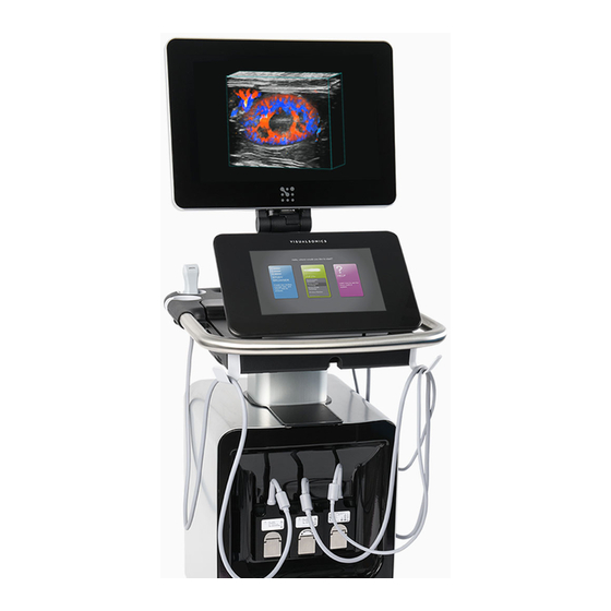
Page 18: System Overview
Vevo F2 Imaging System User Manual System Overview Vevo F2 Imaging System The Vevo F2 Imaging System consists of the following major components: The top screen is the image display, which displays imaging data. The bottom screen is the touchscreen control panel, which serves as the control surface for the system. The base of the system houses the electronics that make up the Vevo F2 Imaging System. The Vevo F2 Imaging System For more information about the system and its components, refer to Components on page 401. Image Display The image display is the top monitor of the Vevo F2, and primarily displays imaging data. Introduction... -
Page 19: Control Panel
Vevo F2 Imaging System User Manual The image display when the system is in B-Mode While the image display varies slightly depending on the current imaging mode, it always displays several categories of data: Imaging information: Contains information such as the name of the study, series, image name, imaging mode, transducer used, as well as various imaging parameters. Image: The current image. This can be a live image or a previously saved image. Animal physiology: Displays the animal's vital signs. Note: For more information about the image display layout, refer to Image Display on page 36. Control Panel The control panel is a touchscreen that displays the Vevo F2 user interface. Introduction... -
Page 20: Basic Touchscreen Actions
Vevo F2 Imaging System User Manual The control panel The control panel contains the following features: A top bar that navigates between menus within the Vevo F2 software. A working area that contains image adjustment controls for the currently selected imaging mode. A collection of control buttons that carry out one of the following functions: Selects an imaging mode Opens features of the currently selected imaging mode Adjusts the current image Executes a function on the current image Customizable sidebars that are used to hold the most commonly used control buttons. Note: For more information about the control panel interface, refer to Control Panel Interface (Scanning) on page 38 and Control Panel Interface (Review) on page 41. Basic Touchscreen Actions The control panel is a touchscreen that serves as the main control interface for the Vevo F2. This screen supports the same actions as those of typical touchscreen devices. The following table lists common touchscreen actions, and a list of Vevo F2 functions that associated with those actions. Introduction... - Page 21 Vevo F2 Imaging System User Manual Gesture Description Associated Actions Adjust depth or gain Move Color Doppler Mode, PA-Mode, and contrast boxes Move measurement calipers Touch the screen with a Move PW Doppler Mode, PW Tissue Doppler Mode finger, and while , or M-Mode sample volume line continuously touching, drag Move PW Doppler Mode or PW Tissue Doppler Drag the finger across the screen Mode baseline before lifting away. Usually Move or drag annotations done to move an object from Pan image in zoom area one location to another. Move through frames in a clip Move controls to the Controls bar Unfreeze a frozen image by dragging the ...
-
Page 22: Onscreen Keyboard
Vevo F2 Imaging System User Manual Onscreen Keyboard You can enter text into text boxes using the onscreen keyboard. Onscreen keyboard 1. Alpha keys: Tap and hold the alpha keys to reveal options for selecting accented versions of the characters. 2. Shift key: Changes alpha keys to between uppercase and lowercase letters. 3. Number/Alpha toggle: Changes between alpha, number, and symbol keyboards. 4. Previous: Jumps to the previous text box. 5. Next: Jumps to the next text box. 6. Spacebar. 7. Keyboard Hide: Hides the onscreen keyboard, or saves entered text. 8. Return: Starts a new line, jumps to the next text box, or dismisses the keyboard. 9. Backspace: Deletes the character to the left of the cursor. To Enter Text 1. Tap a text box (for example, the study name) to open the onscreen keyboard. 2. Tap keys as needed. To Switch Between Numbers and Letters 1. ... -
Page 23: System Startup
Vevo F2 Imaging System User Manual 3. To return to the alpha keyboard, tap the abc key. To Enable Caps Lock 1. Tap a text box (for example, the study name) to open the onscreen keyboard. 2. Tap the shift key twice until the arrow becomes solid green. 3. To disable caps lock, tap the shift key again until it shows the clear arrow. System Startup To turn on the Vevo F2: 1. Connect an AC power cord to the power outlet located at the back of the system, where the power cord connects to the base. Location of the power cord and main power switch 2. Plug the other end of the AC power cord into a wall outlet. Introduction... -
Page 24: To Turn On The Laser Cart
Vevo F2 Imaging System User Manual 3. Turn on the main power switch located at the back of the system, next to where the power cord connects to the base. 4. Press the power button located behind the control panel, near the transducer holders. Location of the power button To Turn On the Laser Cart If using the Vevo LAZR-X laser cart, follow these steps to turn on the laser cart after turning on the Vevo F2. 1. Connect an AC power cord to the power outlet located at the back of the cart. 2. Ensure the emergency stop button is disengaged (rotate it clockwise if it is not). 3. Connect the other end of the AC power cord into a wall outlet with the proper plug. 4. Turn on the main power switch on the back of the laser cart. 5. Confirm the following cables are connected from the system to the laser cart. If using a Vevo LAZRTight, refer to the diagram below. Vevo LAZR-X laser cart Vevo F2 Q Trig In Trig Out Lamp Sync Out Trig In RS232/Remote Introduction... -
Page 25: Logging On For The First Time
Vevo F2 Imaging System User Manual 6. Turn the key switch to the Enable position. 7. Press the ON button on top of the laser cart. 8. Wait at least 20 minutes for the laser to warm up. Logging On for the First Time The first time you turn on the system, you will see the log in screen with two buttons. Introduction... - Page 26 Vevo F2 Imaging System User Manual The startup screen when the system is turned on for the first time The Setup button allows you to create the administrator account for the system. The Guest button allows you to begin imaging immediately as a guest user. However, data saved during this session is not associated with a unique user account, and some system settings are blocked. Introduction...
-
Page 27: To Create The Administrator Account
Vevo F2 Imaging System User Manual To Create the Administrator Account 1. Tap Setup on the login screen. The system opens the following screen: 2. Fill in the following fields: Name Password Confirm Password Note: The password rules listed to the side can be configured in the Password Rules o n page 349 menu. 3. Close the onscreen keyboard and then tap Save. The system creates the administrator user, and then navigates to the Administration p age of the System Settings menu. For more information, refer to Administration on page 339. Introduction... -
Page 28: Quick Start Guide - B-Mode
Vevo F2 Imaging System User Manual Quick Start Guide - B-Mode This tutorial provides a high-level overview for acquiring, analyzing, and exporting a B-Mode image. For more information about imaging sessions, refer to Session Tasks on page 34. Before You Begin Ensure the following: A transducer is connected to a transducer port on the front of the Vevo F2. The animal is properly prepared on the animal platform and connected to the animal monitoring system. WARNING: Before using the Vevo F2 Imaging System, users must read and observe the safety warnings and precautions listed in Vevo F2 Imaging System Safety on page 461. To Acquire, Analyze and Export a B-Mode Image 1. Ensure the system is plugged in, and the main power switch on. 2. Push the power button to start the system. Refer to System Startup on page 23. 3. Log in as a user or a guest. Refer to Logging In on page 34. 4. Choose an application from the transducer panel. The B-Mode imaging window appears, and the system begins acquiring B-Mode data. Refer to Image Display on page 36. 5. Refine your image using the various control panel controls such as Image Depth, Gain, and Orientation. Refer to B-Mode Control Panel Interface on page 109 and B-Mode Controls on page 114. 6. Use the control panel controls to freeze the data image and save clips as needed. ... - Page 29 Vevo F2 Imaging System User Manual Measurements on page 61. d. Once the measurement appears, place the measurement by dragging the calipers. e. When you are done, tap Save Clip to save your image. 10. To export the image, navigate to the Study Browser and then tap Export. Refer to Exporting Images from the Study Browser on page 334. When exporting images: To export as a .csv, .dcm, or .txt file, tap Other File Types. To export to Vevo LAB for further analysis, tap To Vevo LAB. Refer to Exporting Studies to Vevo LAB on page 337. If you have exported your files to Vevo LAB, you can continue with more advanced analysis tools in Vevo LAB. Introduction...
-
Page 30: Quick Start Guide - Pa-Mode
Vevo F2 Imaging System User Manual Quick Start Guide - PA-Mode This tutorial provides a high-level overview for acquiring and analyzing a PA-Mode image and then exporting your data. Note: PA-Mode (Photoacoustics Mode) is only available when the Vevo F2 Imaging System is connected to a Vevo LAZR-X laser cart. Before You Begin Ensure the following: A transducer is connected to the transducer port on the front of the Vevo F2. The transducer is properly equipped with the Vevo Fiber Jacket and Vevo Optical Fiber. The animal is properly prepared on the animal platform and connected to the animal monitoring system. The Vevo Optical Fiber is connected to the appropriate port on the laser cart, according to your imaging needs (Signal 680-970 nm, Idler 1200-2000 nm). The laser is calibrated and warmed up. All safety precautions have been taken. This includes safety precautions related to the test environment, and safety equipment worn by the user. WARNING: Before using PA-Mode, users must read Vevo F2 Imaging System Safety on page 461 and Laser Safety on page 464. To Acquire, Analyze and Export a PA-Mode Image 1. Ensure the Vevo F2 is plugged in, and the main power switch is on. 2. Push the power button to start the Vevo F2. Refer to System Startup on page 23. 3. ... - Page 31 Vevo F2 Imaging System User Manual If the laser hasn't been initialized, the system software will automatically begin the laser initialization process, and display a progress bar. Once initialization is complete, the Laser Configuration panel appears. To configure the laser, refer to Laser Calibration on page 190. 8. Adjust the image and/or specimen until your region of interest is within the PA Guide area. 9. (Optional) To enable the Guide Line in the PA Guide, refer to PA Guide on page 183. 10. Tap Start. The system begins scanning in PA-Mode (Single) at the default wavelength of 750 nm. 11. Use the control panel to refine the image as needed. Refer to PA-Mode Control Panel Interface on page 162. 12. To swap PA-Mode sub-modes, tap the respective sub-mode (such as Spectro). 13. Use the control panel controls to freeze the data image and save clips as needed. To freeze the data acquisition, tap Freeze. Refer to Common Tasks on page 43. To save the clip in the buffer, tap Save Clip. Refer to Saving Frames or Clips on page 99. To resume data acquisition, slide the Slide to Scan control. 14. To view all saved images for the current series, tap the Current Series navigation button. You can also see these images in the Study Browser. Refer to Study Browser on page 320. 15. To open a thumbnail for review, tap the thumbnail. The mode window appears and plays the stored clip. You can navigate through the images stored in the series using the Next/Previous buttons. ...
-
Page 32: Quick Start Guide - Vada Mode
Vevo F2 Imaging System User Manual Quick Start Guide - VADA Mode This tutorial provides high-level instructions for how to acquire, review, save, and export VADA mode data. Note: For more information about VADA Mode, refer to VADA Mode on page 236. Before You Begin Ensure the following: A transducer is connected to a transducer port on the front of the Vevo F2. WARNING: Before using the Vevo F2 Imaging System, users must read and observe the safety warnings and precautions listed in Vevo F2 Imaging System Safety on page 461. To Acquire, Review, Save and Export VADA Mode Data 1. Ensure the system is plugged in, and the main power switch on. 2. Push the power button to start the system. Refer to System Startup on page 23. 3. Log in as a user or a guest. Refer to Logging In on page 34. 4. Choose a transducer and transducer application from the transducer panel. The B-Mode imaging window appears, and the system begins acquiring B-Mode data. Refer to Image Display on page 36. 5. Tap VADA. The system switches to VADA Mode. 6. Open the VADA configuration panel and set an active pulse sequence. Refer to Navigation on page 251. a. (Optional) Tap Waveforms to open the Waveforms menu, then edit or create waveforms as needed. Refer to Waveforms on page 264. - Page 33 Vevo F2 Imaging System User Manual Note: The Review menu opens automatically if Automatically open review panel after acquisition is turned on in the Clip Settings menu. 9. If not yet saved, tap Save to save the data. Note: Data is saved automatically if Automatically save after acquisition is turned on in the Clip Settings menu. 10. To export the image, navigate to the Study Browser, ensure your saved image is selected, then tap Export. Refer to Exporting Images from the Study Browser on page 334. When exporting images: To export as a .csv, .dcm, or .txt file, tap Other File Types. To export to Vevo LAB for further analysis, tap To Vevo LAB. Refer to Exporting Studies to Vevo LAB on page 337. If you have exported your files to Vevo LAB, you can continue with more advanced analysis tools in Vevo LAB. Introduction...
-
Page 34: Session Tasks
Vevo F2 Imaging System User Manual Session Tasks An imaging session involves either scanning and acquiring a new image, or reviewing an image saved from a previous imaging session. A typical imaging session consists of the following steps: 1. Turn on the Vevo F2 (refer to System Startup on page 23). 2. Log into the Vevo F2 (refer to Logging In below). 3. Acquire an image, or open a previously saved image. To acquire an image, select a transducer and an imaging mode (from the Modes on page 108), then position the transducer on the animal. To open a previously saved image, refer to Working with Images on page 332. 4. Navigate the interface, using the controls to switch viewing modes and adjust the image as necessary. For more information, refer to: Image Display on page 36 Control Panel Interface (Scanning) on page 38 Control Panel Interface (Review) on page 41 5. Add markup to the image, such as: Annotations on page 56 Measurements on page 61 6. Save the image (refer to Saving Frames or Clips on page 99). 7. Log out (refer to Logging Out on page 107). Note: This section assumes that the Vevo F2 Imaging System, Vevo LAZR-X ... -
Page 35: Interface Overview
Vevo F2 Imaging System User Manual The login page To log in: 1. At the login page, tap the appropriate user ID. If you have a user ID, select your user ID. If you do not have an account, tap Guest. Note: User accounts must be created by an administrator. For more information, refer to Add a New User. Note: If no accounts have been made, refer to Logging On for the First Time on page 25. 2. If prompted, enter your password and tap Log in. Interface Overview Once logged in, the Vevo F2 interface appears. This interface is split between two screens: Session Tasks... -
Page 36: Image Display
Vevo F2 Imaging System User Manual The image display: The top monitor, which displays imaging data. The control panel: The bottom touch screen, which serves as the interface for the system. Image Display The image display displays imaging data. The following example is from a B-Mode image. Note: The interface shown on the image display may vary depending on scanning mode. The image display when in B-Mode. The image display interface is split into common elements that appear across all imaging modes, and a central working area that contains elements specific to the active imaging mode. This section lists all common interface elements. For information about mode-specific elements, refer to subsections linked from the Modes on page 108. Common Interface Elements: Session Tasks... - Page 37 Vevo F2 Imaging System User Manual 1. Image 2. Image status area 3. Mode settings panel 4. Image scale 5. Physiological data trace 6. Clip buffer 7. Status bar Image This area displays the current image, which is either a live image, a frozen image taken from the live image, or a previously saved image. Image Status Area This area contains general information about the current image. Information displayed includes: The transducer currently in use Study/series information Image status (whether it is a live image, or an image in review) Mode-specific information (which varies depending on the current imaging mode) Mode Settings Panel The mode settings panel displays a unique set of i nformation depending on the current mode. Specific values for image controls are displayed. As you modify the settings during imaging, your changes ...
-
Page 38: Control Panel Interface (Scanning)
Vevo F2 Imaging System User Manual Clip Buffer Displays the length of the clip. When in review mode, there is a triangular white marker that identifies t he individual frame number within the clip. To display a sub-range of the original clip, use the Clip Sub-range button (refer to Clip Sub-range). Status Bar The following information is shown on the status bar: Monitored physiological values in real time during image acquisition, if the Vevo Imaging Station is connected and the system is configured appropriately. These value are color-coded to correspond to the physiological trace. Percentage of free space available for image data. Used to see when you should start to back up image data to free up space on the system. Current user name. Current t ime. Current Vevo Voice state (if enabled). Laser status (if PA-Mode is initialized). Various status updates when imaging parameters are changed and some image processing progress information. Control Panel Interface (Scanning) During an imaging session, the control panel displays universal controls that can be used during any scanning session, as well as controls that are specific to the currently selected scanning mode. - Page 39 Vevo F2 Imaging System User Manual 1. Navigation Bar 2. Tabs 3. List of Scanning Modes 4. Mode-Specific Controls 5. General Controls 6. Imaging Controls Navigation Bar The bar across the top of the interface contains a series of items that are used to access studies, applications, and other menus in the Vevo F2 software. Tap an item on the navigation bar to navigate to the respective menu. Study Browser: Opens the Study Browser. Current Series: Opens the current series. Application: Opens the application menu, which allows the user to switch application packages and transducers. More: Opens a submenu that leads to the following features: Help System Settings Lock Log Out Session Tasks...
- Page 40 Vevo F2 Imaging System User Manual Tabs This is a series of tabs that lead to additional control panels related to the imaging session. 3D/4D tab: Used to set up 3D or 4D scanning. Only applicable to certain imaging modes. Physiology: Used to access the animal monitor menu, which manages and tracks the animal's physiology during an imaging session. Laser: Used for laser-specific functions when in PA-Mode. Only appears when the laser is initialized. EKV/Laser: Only applicable to certain imaging modes. This tab only appears in certain modes. List of Scanning Modes The bar to the left of the interface features a customizable list of scanning modes. This list serves as a hotbar, allowing the user to quickly swap between modes during an imaging session. To switch scanning modes, tap the appropriate mode button (such as B-Mode). Note: To set which modes appear on this bar, refer to Mode Controls on page 92. Mode-Specific Controls The gray square in the middle of the interface, and the immediate area surrounding it, contain controls that are specific to the currently selected imaging mode. This includes controls that adjust the image to bring desired elements into focus. For example, when scanning in B-Mode, this area contains controls for things such as focus, depth, gain, and TGC control. For a list of each mode's mode-specific controls, refer to Modes on page 108. General Controls The bar along the bottom of the interface contains controls that are universal to all imaging modes. This includes functions such as: Freeze: Freezes the current frame of the image for viewing or to insert markups (such as ...
-
Page 41: Control Panel Interface (Review)
Vevo F2 Imaging System User Manual Save Clip: Saves the currently captured images as a video clip. Vevo Voice: Refers to the Vevo Voice feature. For more information, refer to Vevo Voice on page 396. Note: For more information about general controls, refer to General Controls on page 93. Imaging Controls The bar along the right of the interface contains controls that adjust or refine the image. This list serves as a hotbar, allowing the user to easily access commonly used adjustment features. To use an imaging control, tap the control mode button. To set which imaging controls appear on this bar, tap More Controls. Note: For more information about the More Controls menu, refer to Imaging Controls on page 97. Control Panel Interface (Review) When viewing a previously saved image, the control panel displays a different set of controls than those that appear during a scanning session. The controls that appear when reviewing an image allow the user to manipulate the view of the recorded image, as well as add markup to it. Note: The control layout in review mode is stored separately from the control layout in scanning mode. Users can customize the control layout in one mode without interfering with the layout in the other mode. The control panel interface is split into the following sections. Session Tasks... - Page 42 Vevo F2 Imaging System User Manual 1. Play Speed 2. Clip slider 3. Play/Pause 4. Delete 5. Export 6. Slide to Scan 7. Next/Previous Image Play Speed Adjusts the playback speed of a clip. To adjust the play speed, tap this button, then use the Up and Down buttons to increase or decrease the play speed. This control is not available when reviewing images that consist of a single frame. Clip Slider Shows the current position and frame viewed in a clip. To view different frames in a clip, drag this slider along the line. To view the next or previous frame in the clip, use the arrow buttons at the each end of the slider. This control is not available when reviewing images that consist of a single frame. Play/Pause Plays, pauses, or resumes the currently selected clip. Not available when viewing single image frames. Session Tasks...
-
Page 43: Common Tasks
Vevo F2 Imaging System User Manual Delete Deletes the current image. You will be prompted with a confirmation message before the image is deleted. Only available when viewing saved images. Export Exports the current image. Slide to Scan Used to resume live imaging. To use this control, slide the green arrow to the right. Next/Previous Image Used to switch to the next or previous image in the series. Only available when viewing saved images. Common Tasks During an imaging session, the Image Display shows a live feed of the image, and the control panel shows an interface specific to the currently selected mode. You can do any of the following tasks at any time during an imaging session: Change modes Change transducers or applications Adjust the image Freeze the image or resume scanning Insert markup into the image The following markup types are available: Annotations Measurements Change the controls shown on the control panel ... -
Page 44: Adjust Image
Vevo F2 Imaging System User Manual Adjust Image To adjust the image currently displayed, use the imaging controls on the control panel. Image adjustment controls vary between modes. For more information about the image adjustment controls for a particular mode, refer to the list of controls for that mode. For example, for B-Mode controls, refer to B- Mode Control Panel Interface on page 109. Freeze Image/Resume Scanning Certain tasks, such as viewing a clip or adding measurements, require you to stop live imaging by freezing the image. To freeze t he image at any time, tap FREEZE. When an image is frozen, the bottom bar of the control panel changes to a Slide to Scan slider. To resume live imaging, drag the green arrow in the Slide to Scan slider to the right. Using the Slide to Scan slider returns the interface to the live image. Insert Markup There are several types of markup that can be added to an image: Measurements on page 61: A marker highlighting a measurement, such as angle or distance. Annotations on page 56: User-entered notes that are embedded into the image. Change Controls on Control Panel Most buttons along the left, bottom, and right bars on the control panel are interchangeable. Users can ... -
Page 45: Selecting A Transducer Or Application
Vevo F2 Imaging System User Manual Selecting a Transducer or Application Transducers and applications are selected in two different parts of the interface: From the Home screen From the Application menu For information about how to manage applications, refer to Manage Applications on page 367. Selecting a Transducer or Application from the Home Screen By default, the Home screen appears after logging in. Note: The Home screen can be skipped by selecting a different startup page in the General section of the System Settings menu. For more information, refer to Startup. On the Home screen, a green button appears. This button contains the following information: Session Tasks... - Page 46 Vevo F2 Imaging System User Manual The name at the top is the model of the transducer. The gray list is a list of applications for the transducer. The three circles below the button represent the three transducer ports at the front of the system. Each circle represents the status of each transducer interface. A green filled circle represents the currently selected transducer port. The empty circles represent transducer ports that are currently not connected to a transducer. To Select a Transducer and Application After Logging In 1. Tap the appropriate circle for the transducer interface you intend to use. 2. When the transducer appears, tap the desired application for the transducer. A progress bar will appear while the selected transducer and application are initialized. Once initialization is complete, the scanning interface appears. Selecting a Transducer or Application From the Application Menu During an imaging session, you can switch transducers or applications at any time through the Application ...
-
Page 47: Physiology Settings
Vevo F2 Imaging System User Manual 2. Tap the desired transducer or application. A progress bar will appear while the selected transducer and application are initialized. Once initialization is complete, the scanning interface appears. Physiology Settings The Physiology panel controls features related to the animal's physiological data. This data is captured by the Vevo Animal Monitoring System (also known as the Vevo Monitor) and fed to the Vevo F2 Imaging System. Note: This section only refers to features available on the Vevo F2 Imaging System. For more information about the Vevo Animal Monitoring System, refer to the Vevo Animal Monitoring System User Guide. Session Tasks... - Page 48 Vevo F2 Imaging System User Manual The Vevo Animal Monitoring System, which feeds physiology data to the Vevo F2 Navigation To open the Physiology panel, tap the Physiology tab on the control panel. Session Tasks...
- Page 49 Vevo F2 Imaging System User Manual The Physiology panel consists of three collapsible sections, with each section dedicated to one feature: Live Monitoring (Physiology Live Monitoring below) Respiration Gating (Respiration Gating on page 51) ECG Trigger (ECG Trigger on page 53) To expand a section, tap the blue title bar of that section. To collapse it, tap the bar again. To activate a feature, tap the On/Off slider next to the title. Physiology Live Monitoring The Live Monitoring section of the Physiology panel is split into two tabs: Monitor: Controls how physiological information is displayed on the image display. Alarm: Sets the physiological thresholds for what is considered safe. If the feed exceeds any limits defined here, the numerical display at the bottom of the image display will blink to alert the user. Session Tasks...
- Page 50 Vevo F2 Imaging System User Manual Monitor The Monitor tab This section lists physiological metrics by column. Each column features the following controls to control how that metric appears on the image display: Select or clear the check box at the top of a column to display or hide that metric on the image display. Move the Scale slider to change the size of the metric. Move the Offset slider to display the metric with an offset (moves the line up or down). (Resp only) Tap the Invert check box to invert the curve. (BP only) Tap Calibrate to calibrate the blood pressure measuring device. This navigates to a separate panel where you can either import calibration settings for a specific device model, or manually calibrate the device yourself. Session Tasks...
- Page 51 Vevo F2 Imaging System User Manual Alarm The Alarm tab This section lists physiological metrics by column. Each column features the following controls to control how alarms are set for that metric. Select or clear the check box at the top of a column to enable or disable alarms for that metric. For each metric, drag the High and Low dials up and down to set the upper and lower safe limits for that metric. If the feed exceeds any limits defined here, the live numerical display at the bottom of the image display will blink. Respiration Gating Respiration gating is used to suppress variations in measurements caused by the subject's chest cavity moving as it breathes. Respiration gating is only available for frame-based imaging modes, such as: B-Mode Color Doppler Mode Power Doppler Mode Nonlinear Contrast Mode PA-Mode Session Tasks...
- Page 52 Vevo F2 Imaging System User Manual How Respiration Gating Works Respiration gating instructs the imaging system to record image data only when the subject is between breaths, which is when the body moves the least from breathing. To do this, the user must first identify this point in the breathing cycle from physiological data, and set that point in the system. With proper respiration gating, the imaging system only captures data during the shaded area How to Use Respiration Gating Respiration gating is set in the Respiration Gating section of the Physiology panel. The Respiration Gating panel Session Tasks...
- Page 53 Vevo F2 Imaging System User Manual To Turn On Respiration Gating 1. Select an imaging mode that supports respiration gating. 2. Tap the Physiology icon. 3. In the Live Monitoring section, ensure that Live Monitoring is on, and that Resp (respiration) is enabled. 4. In the Respiration column, adjust the range and offset so that the trace line fits these properties: The peaks and valleys do not extend above or below the window. The peaks are tall enough to be clearly visible. 5. Open the Respiration gating section and enable it. The orange section on the image display is the gate area, and corresponds to the orange section on the control panel. 6. While watching the respiration signal on the image display as reference, use the respiration gate controls on the control panel to set the respiration gate to capture a period of time between breaths. The respiration gate controls can be adjusted as follows: Drag the colored area in the middle of the bar to move the gate area. Drag the handles on each side of the bar to adjust the start and end points of the gate area. You can also tap the arrows on either side to make small adjustments. 7. Once all settings are complete, tap away from the Physiology panel to close it. ECG Trigger ECG triggering is used to suppress variations in measurements caused by the physical movement of the ...
- Page 54 Vevo F2 Imaging System User Manual How the ECG Trigger Works ECG triggering acquires one single frame of image data during each cardiac cycle, at precisely the same time point after the R wave peak. The result of this triggering is a clip of a nearly static heart. It can also be used to acquire two frames at two specific time points after the R wave. How ECG Triggering works How to Use the ECG Trigger ECG Trigger settings are controlled in the ECG Trigger section of the Physiology panel. The ECG Trigger panel Session Tasks...
- Page 55 Vevo F2 Imaging System User Manual To Turn On ECG Triggering 1. Select an imaging mode that supports ECG triggering. 2. Tap the Physiology icon. 3. In the Live Monitoring section, ensure that Live Monitoring is on, and that ECG is enabled. 4. In the ECG column, adjust the range and offset so that the trace line fits these properties: The peaks and valleys do not extend above or below the window. The peak of the R wave is clearly defined. Note: You may want to temporarily turn off other physiology signals during this step to more clearly see the R wave. Signals can be turned on and off in the Live Monitoring section of the Physiology panel. 5. Open the ECG Trigger section and enable it. Note: The status of the ECG trigger is shown on the mode settings panel on the image display, under Acquisition. 6. Tap t1 to activate the systole time slider control. The systole slider appears on the bar, and becomes selectable. 7. While watching the image display, adjust the slider until you find the desired image in the cardiac cycle. The system sets the selected time point on the R wave, and acquire one single frame of image data during each cardiac cycle. 8. ...
-
Page 56: Annotations
Vevo F2 Imaging System User Manual The ECG Trigger panel, with both triggers set Annotations Annotations are text labels that you can add to any image. When you store an annotated frame or clip, the system stores the a nnotations along with the image. T his topic describes how to work with annotations when you are analyzing an a cquired image. Predefined Annotations When placing an annotation on an image, an annotations page appears with a list of predefined labels. Session Tasks... - Page 57 Vevo F2 Imaging System User Manual Annotations page You can also create and save custom predefined labels in the System Settings menu. See Measurements & Annotations on page 380. To Add an Annotation 1. Select the image you want to annotate in one of the following ways: Acquire an image with the Freeze button. Load an image from the Study Browser. Select an image from the Current Series option from the top menu. 2. In the imaging controls, tap Annotations. The Annotations page is displayed. Session Tasks...
- Page 58 Vevo F2 Imaging System User Manual 3. You can select a predefined annotation, or enter custom text. To enter a predefined annotation, select the category from the top of the page, then select the predefined label you want to add. To enter custom text, tap the text entry area to show the onscreen keyboard. Enter the text you want to add as a one time custom annotation. 4. (Optional) Tap the Show arrow checkbox to show an arrow when the annotation is dragged. 5. Tap Done to add the annotation. The annotation is placed on the image. You can then interact with the annotation using the control panel. Note: While you are placing the annotation, a magnified view of the placement area is displayed on the image display to help with a more accurate placement. 6. Drag the annotation to the desired location on the image. 7. Annotations on the image will be shown on the Annotations panel on the left of the control panel. Use the Annotations panel to edit the annotations. Session Tasks...
- Page 59 Vevo F2 Imaging System User Manual To Change Annotation Properties Each annotation has its own set of properties that you can modify. 1. Tap the annotation that you want to modify in the Annotation panel. 2. Tap the Properties button. The Annotation Properties screen is displayed. Label: Tap the text box and modify the existing label as needed. Font size: Tap the Font Size and select the preferred size – range is from 6 to 48. The default font size is set in the system settings. See Measurements & Annotations on page 380. Show arrow: Select whether or not to show an arrow from the text to a location on the image. Label Location: Specify whether you want to show the annotations on the current frame of a clip or on each frame of the clip. This option is only available for frame-based modes. Session Tasks...
- Page 60 Vevo F2 Imaging System User Manual Annotation properties menu To Edit an Annotation Once an annotation is placed, you can edit the text. The image is saved automatically after you edit an annotation. 1. Tap the annotation on the image or on the Annotation panel. 2. Tap the Edit button and edit the text or select another predefined annotation. To Move an Annotation Once an annotation is placed, you can move it to a different location on the image. The image is saved automatically after you move an annotation. 1. Tap the annotation on the image or on the Annotation panel. The annotation will change color. 2. Drag the annotation to the desired location. If an arrow is part of the annotation, the head of the arrow stays at the location on the image while you move the text. You can drag the arrow head separately, if required. Session Tasks...
-
Page 61: Measurements
Vevo F2 Imaging System User Manual The following example shows the arrow head selected for editing. 3. When the move is complete, lift your finger to commit the change. To Delete an Annotation 1. On the Annotations panel, tap the measurement you want to delete. 2. Tap the Delete button displayed below the selected annotation. The annotation will be immediately deleted. 3. If you want to delete all of the annotations on the selected image, tap Delete All. located at the bottom of the Annotation panel. You will be prompted to confirm the deletion of all annotations. The annotation(s) are deleted from the image and the Annotations panel. Measurements The Vevo Imaging System offers several types of generic measurements. This section lists available generic measurements, and describes how to a dd each one. Note: Available measurements vary depending on the currently selected imaging mode. Measurements are only available for imaging modes that support them. When adding generic measurements, please note the following: Measurements will be displayed on the image display and the control panel. ... - Page 62 Vevo F2 Imaging System User Manual Using the Measurements Panel The Measurements panel provides tools for editing measurements on an image and options to change which measurement properties are displayed. The Measurements panel is only displayed once the first measurement is placed on an acquired or saved image. The panel is not available during image acquisition. Note: You must pause a clip before you can place a new measurement or interact with previously saved measurements. Common Tasks To View Available Generic Measurements for an Image 1. Load/acquire an image into review by doing one of the following: If you are in the Study Browser open a saved image. If the image is a clip, then pause the clip at the frame you want to work with. If you are acquiring image data, tap Freeze on the control panel. Select an image from the Current Series option from the top menu. 2. View the available measurements by tapping the M easurements button. Only the available measurements for the active mode will be available.
- Page 63 Vevo F2 Imaging System User Manual 3. Interact with the measurement using the control panel. When placing a measurement, a magnified view of the placement area is displayed on the image display. To change the magnification, tap Magnify Scale and then use the Increase or Decrease buttons. A measurement label is displayed next to the measurement on the image. It contains the measurement's label, number, and value. Note: The zoom scale factor can be changed while placing measurement. Changing the zoom value does not affect the measurement value, parameters, or font size. To Use the Measurements Panel Once a measurement is added, a Measurements panel appears on the left side of the control panel. Use this panel to select and edit measurements. To expand or collapse the Measurements panel, tap the down or up arrows. Session Tasks...
- Page 64 Vevo F2 Imaging System User Manual To Modify Measurement Properties Each measurement has its own set of measurement properties that you can modify. 1. Tap a measurement in the Measurements panel. 2. Tap the Properties button. 3. The Measurement Properties panel is displayed. Label: Tap the text box and modify the existing label as required. Font Size: Tap the Font Size and select the preferred size; range is from 6 to 48. Show Physiological Parameters: Select to show physiological parameters on both the measurement label and on the Measurement panel. 4. Tap the parameters that you want to display. The number and type of items displayed changes depending on the type of measurement that is selected. To Delete a Measurement 1. On the Measurements panel, tap the measurement you want to delete. 2. Tap the Delete button displayed below the selected measurement. To delete all measurements on an image, tap Delete All at the bottom of the Measurements panel, and accept the confirmation prompt that appears. ...
- Page 65 Vevo F2 Imaging System User Manual To Edit a Measurement Once a measurement is placed, you can edit individual anchor points along the measurement. After you edit a measurement, the system software automatically saves the image. Note: Not all measurements can be modified after being placed. If you cannot modify a measurement, delete the measurement and add it again. To edit a measurement: 1. Tap the measurement on the image or on the Measurements panel. The measurement will change color from cyan to white. 2. Tap and drag one of the measurement anchor points to the desired position. The measurement parameters automatically update on the Measurements panel. Note: Moving a measurement anchor point for a depth or time measurement will also allow you to change the location of the measurement at the same time. To Move a Measurement Once a measurement is placed, you can move the entire measurement to a different location on the image while maintaining its original measurement value. The image is saved automatically after you have moved your measurement. 1. Tap the measurement on the image or on the Measurement panel. When the measurement is active, it changes color to white. 2. If the measurement has a center anchor point, tap the center of the measurement. If there is no Session Tasks...
- Page 66 Vevo F2 Imaging System User Manual center anchor point, then drag the measurement line. 3. When the move is complete, lift your finger and tap anywhere outside of the measurement area to commit the measurement. Angle The angle measurement is available in B-Mode and PA-Mode., Color Doppler Mode, Power Doppler Mode, Nonlinear Contrast Mode, and EKV. To Add an Angle Measurement 1. Tap Measurements. 2. Tap Angle. The measurement is placed on the image. 3. You can select any of the 3 anchor points for editing. Tap and drag an anchor anywhere on the image. As you move the anchor points, the parameters are updated on the Measurements panel. See Using the Measurements Panel on page 62. Session Tasks...
- Page 67 Vevo F2 Imaging System User Manual 4. Tap and drag either one of the two measurement lines to move the whole measurement. 5. The measurement and image are automatically saved as the measurement is adjusted. Area Area measurements are available in B-Mode, PA-Mode, Color Doppler Mode, Power Doppler Mode, Nonlinear Contrast Mode, and EKV. To Add an Area Measurement 1. Tap Measurements. 2. Tap Area. An active anchor i s placed on the image. Session Tasks...
- Page 68 Vevo F2 Imaging System User Manual 3. Tap and drag the active anchor to the desired location on the image. When you have placed the anchor in the desired starting position, tap Set. 4. Tap and drag the handle to draw the measurement within the image area. 5. When you are finished drawing your measurement, lift your finger from the control panel and tap Done. 6. (Optional) Tap and drag the line of the area to move the entire measurement while maintaining the area. 7. The measurement and image are automatically saved after the measurement is moved. Session Tasks...
- Page 69 Vevo F2 Imaging System User Manual To Create a Histogram for the Area 1. Tap the measurement from the Measurements panel for which you want to create the histogram. Refer to Using the Measurements Panel on page 62. 2. Tap the Graph icon for the selected measurement. The histogram appears. The system can be set up to use either image data or raw data when generating the histogram. When using image data, the brightness and contrast settings are taken into account. The histogram contains information about the pixel count scale of the image data or raw data, the mean, and the standard deviation. Session Tasks...
- Page 70 Vevo F2 Imaging System User Manual Note: The histogram is calculated based on the part of the measurement that was visible on the control panel when you tapped the Graph icon. If the area measurement was obscured in any way (such as if the control panel was zoomed in to not fully show the Area measurement), the histogram displayed will not be accurate. If this happens, zoom back out and make sure the entire measurement is visible on screen before tapping the Graph icon again. 3. Tap Close to return to the image. Distance Distance measurements are available in B-Mode, PA-Mode, Color Doppler Mode, Power Doppler Mode, and Nonlinear Contrast Mode. To Add a Distance Measurement 1. Tap Measurements. 2. Tap Distance. An active anchor for the measurement is placed on the image. 3. Tap and drag the anchor point to the desired location on the image. 4. Tap Set when you have placed your anchor at the desired start location. 5. Tap and drag the anchor point to trace the distance on the image area. Session Tasks...
- Page 71 Vevo F2 Imaging System User Manual 6. When you are finished drawing your measurement, lift your finger from the control panel and tap Done. 7. (Optional) Tap and drag the line of the measurement to move the measurement to another location on the image. 8. The measurement and image are automatically saved as the measurement is adjusted. Ellipse Ellipse measurements are available in B-Mode, Color Doppler Mode, Power Doppler Mode, Nonlinear Contrast Mode, and PA-Mode. Session Tasks...
- Page 72 Vevo F2 Imaging System User Manual Note: The volume estimate from an ellipse measurement is based on the following: 2 Volume = 0.52 x width x length The 'width' component of the formula is the lesser of the two axes of the ellipse measurement, while the 'length' component is the greater. To Add an Ellipse Measurement 1. Tap Measurements. 2. Tap Ellipse. The ellipse measurement is placed on the image. 3. Tap and drag one of the line points to the desired location on the image. As you move the point, the measured length is updated on the Measurements panel. Refer to Using the Measurements Panel on page 62. Session Tasks...
- Page 73 Vevo F2 Imaging System User Manual 4. (Optional) Tap and drag the center point to move the entire measurement while maintaining the ellipse. The measurement and image are automatically saved as the measurement is adjusted. 5. Remove your finger from the control panel to commit the measurement. Linear Linear measurements are available in B-Mode, Color Doppler Mode, Power Doppler Mode, Nonlinear Contrast Mode, and PA-Mode. To Add a Linear Measurement 1. Tap the Measurements button. 2. Tap the Linear button. Session Tasks...
- Page 74 Vevo F2 Imaging System User Manual The linear measurement is placed on the image. 3. Tap and drag one of the end points to the desired location on the image. As you move the point, the measured length is updated on the Measurements panel. See Using the Measurements Panel on page 62. 4. Tap and drag the measurement line to move the entire measurement. 5. The measurement and image are automatically saved as the measurement is adjusted. Session Tasks...
- Page 75 Vevo F2 Imaging System User Manual PA Region The PA (Photoacoustic) Region measurement traces a region of interest on a PA frame. The Vevo software then measures the total area of the defined PA region. Quantification is available for the average threshold signal power of each P A Region measurement displayed by the label "PA Thresh". Quantification is also available for the average signal power and the average threshold signal power for Multiplexed PA Region measurements. Displayed by the label "Avr" and "Thresh" preceded by the Layer name. For more details on placing a PA Region measurement on a Multiplexed image, refer to To Measure Signal Changes in a PA-Mode (Multi-wavelength) Loop on page 81. Placing PA Region Measurements You can draw up to 20 PA Region measurements on one image. To Place a PA Region Measurement 1. Tap Measurements. 2. Tap PA Region. Session Tasks...
- Page 76 Vevo F2 Imaging System User Manual An active anchor point for the measurement appears on the image. 3. Drag the anchor point to the desired start point, and then tap Set. 4. Tap and drag the anchor point to trace the desired area. 5. When you are done drawing your measurement, lift your finger from the control panel and tap Done. Session Tasks...
- Page 77 Vevo F2 Imaging System User Manual 6. (Optional) You can edit any point on the measurement by tapping and dragging the point anywhere on the image. 7. (Optional) To move the entire measurement to another location while maintaining the area, tap and drag the center point of the area. 8. Lift your finger after you have completed your edits. Tap anywhere outside of the measurement area to commit the measurement. Subsequent PA Region measurements placed on the image will b e colored differently by the system. 9. Once the PA Region is placed, the measurement parameters are updated on the Measurement panel. Refer to Using the Measurements Panel on page 62. Session Tasks...
- Page 78 Vevo F2 Imaging System User Manual 10. You can also copy a measurement. Refer to Copying and Pasting PA Region Measurements below. Copying and Pasting PA Region Measurements When copying and pasting PA Region measurement, please keep the following in mind: You can copy a PA Region measurement from a PA-Mode image and paste it to a nother PA-Mode image image. Pasting a measurement on the destination image will only be allowed if the image area is large enough to fit the copied measurement. Copying and pasting supports one or multiple measurements and is only available while reviewing an image in the 2D view. 20 PA Regions are allowed on one PA-Mode image. To Copy a Single PA Region Measurement 1. Tap the PA Region measurement you wish to copy. 2. Tap the copy button. 3. Acquire a new image, load an image into review or use the currently loaded image. Session Tasks...
- Page 79 Vevo F2 Imaging System User Manual 4. Tap Paste Regions. 5. The copied PA Region measurement is placed on the image, with its original coordinates. To Copy and Paste all PA Region Measurements 1. Tap Copy Regions from the Measurements panel. 2. Acquire a new image, load an image into review or use the currently loaded image. 3. Tap Paste Regions. 4. The copied PA Region measurements are placed on the image, with their original coordinates. Creating PA Region Graphs Use the PA Region Graph t o measure and graph the changes in PA-Mode data across time or frames in a defined region. Define the region of interest, then generate a graph that measures the signal changes that appear in that region over your PA-Mode cine loop. Quantification is available for the average threshold signal power of each P A Region measurement. Displayed by the label 'PA Avr Thresh', quantification values represent the average maximum intensity and ...
- Page 80 Vevo F2 Imaging System User Manual The PA Region Analysis screen 3. You can now edit how the analysis is displayed. The available settings are different for each PA sub- mode. PA-Mode (Single): Display Options – A uto Scale and PA Average or PA Average Threshold for the Y axis. Chart X Axis – Time Scale or Frame Scale PA Regions – When displaying multiple regions, you can choose to display one, some, or all on one graph. You can also choose a different color for the data on the chart for each PA Region displayed. PA-Mode (Spectro): Display Options – Auto Scale and PA Average or PA Average Threshold for the Y axis. PA Regions – When displaying multiple regions, you can choose to display one, some, or all on one graph. You can also choose a different color for the data on the chart for each PA Region displayed. For a PA-Mode (Spectro) image, you also have a Save Spectral Curves button to save a custom curve. Note: The Save Spectral Curves button is only available for Spectro images that have acquired the full wavelength range. Session Tasks...
- Page 81 Vevo F2 Imaging System User Manual Note: Your custom curve will be displayed in the Select Components list on the Spectral Curves window found on the Photoacoustics page in System Settings, in the Unmixing panel a nd the Multi-wavelength setup panel. PA-Mode (Oxy-Hemo): Display Options – Auto Scale and sO Average, sO Average Total, HbT Average or HbT Average Threshold for the Y axis. Chart X Axis – Time Scale or Frame Scale PA Regions – When displaying multiple regions, you can choose to display one, some, or all on one graph. You can also choose a different color for the data on the chart for each PA Region displayed. PA-Mode (Multi-wavelength): Display Options – A uto Scale and PA Average or PA Average Threshold for the Y axis. Chart Y Axis – Choose whether or not to Separate Wavelengths. Chart X Axis – Time Scale or Frame Scale. PA Regions – When displaying multiple regions, you can choose to display one, some, or all on one graph. You can also choose a different color for the data on the chart for each PA Region displayed. PA Wavelengths – Only displayed when the Separate Wavelengths option is enabled. Choose which wavelengths to display on the graph and what icon you want for each ...
- Page 82 Vevo F2 Imaging System User Manual 6. The system software calculates the PA signal within the boundaries of the region curve and displays the data in the PA Region Analysis window. 7. The PA Region Analysis window is different depending on if the image is Multiplexed or not. If you chose not to Multiplex your image, a Separate Wavelengths option is available under the Chart Y Axis section. Tap the Separate Wavelengths checkbox to allow separation of the curve based on wavelength. Once the Separate Wavelengths option is checked, all of the wavelengths used to acquire the image are displayed. Uncheck the wavelengths that you do not want displayed on your graph and select what icon the data line will be displayed with on the graph. Session Tasks...
- Page 83 Vevo F2 Imaging System User Manual If you chose to Multiplex your image, the layers are automatically separated and the Separate Components checkbox becomes disabled. Select which layers will be displayed by checking or unchecking the layers listed in the PA Layers section of the PA Region Analysis window. Toggle to display the additional measurement options—PA Average (Calculation) and PA Average Threshold (Calculation)—from the Display Options section. To Measure Signal Changes in a PA-Mode (Spectro) Loop 1. Acquire or load a PA-Mode ( Spectro) image to review. 2. Tap Measurements, then tap PA Region. 3. Place your measurement, as described in To Measure Signal Changes in a PA-Mode (Spectro) Loop above. 4. Tap the PA Region on the Measurement panel, then tap the graph icon. 5. The system software calculates the PA signal within the boundaries of the region curve and displays the data in the PA Region Analysis window. Session Tasks...
- Page 84 Vevo F2 Imaging System User Manual 6. The PA Region Analysis window is different depending on if the image is Multiplexed or not. If you chose not to Multiplex your image, an additional Save Spectral Curves option is available in the PA Regions section. The PA Region(s) will also be listed with the option to enable/disable and the option to select what color the line of data will be displayed as on the graph. Note: Once the spectral curve is saved, you will see your curve on the Photoacoustics page in System Settings. See Photoacoustics on page 383 for more information. To save a spectral curve: i. On a PA-Mode (Spectro) image with a PA Region, tap the graph button. ii. Tap Save Spectral Curves. The Save Spectral Curves panel is displayed. iii. Select w hich PA Region to save by tapping the check box for each PA Region you want to save. iv. (Optional) Change the PA Region default name by tapping the text box and typing a new name. Session Tasks...
- Page 85 Vevo F2 Imaging System User Manual v. (Optional) Tap the Display Map drop down and choose a color. When unmixing a Multi- wavelength or Spectro image, the default display map for the component will be set to this option. vi. (Optional) Tap Select Group to display a tree that lists all available groups. Select an existing group for your PA Region or create a new group. vii. Tap Save when you are done. If you chose to Multiplex your image, you h ave the option to check or uncheck each PA Region and the ability to select what color the line of data will be displayed as on the graph. To Measure Blood Oxygenation in a PA-Mode (Oxy-Hemo) Loop When you are analyzing an Oxy-Hemo sub-mode image, you can select specific regions of interest and precisely measure the percentage level of blood oxygenation in that region. The Vevo Imaging System provides two display types for Oxy-Hemo acquisition. Choose the appropriate display before taking measurements: OxyZated Display Type: Used to calculate and quantify oxygen saturation; also particularly useful for studying the hypoxic state of tumor microenvironment to predict disease burden, studying fetal/maternal physiology, and studying stroke/ischemia. HemoMeaZure Display Type: Used to measure and quantify hemoglobin content; also particularly ...
- Page 86 Vevo F2 Imaging System User Manual To Place a Contrast Region Measurement 1. Tap Measurements. 2. Tap Contrast Region. An active anchor point for the measurement appears on the image. 3. Drag the anchor point to the desired start point, and then tap Set. 4. Tap and drag the anchor point to trace the desired area. 5. When you are done drawing your measurement, lift your finger from the control panel and tap Done. Session Tasks...
- Page 87 Vevo F2 Imaging System User Manual 6. (Optional) You can edit any point on the measurement by tapping and dragging the point anywhere on the image. 7. (Optional) To move the entire measurement to another location while maintaining the area, tap and drag the center point of the area. 8. Lift your finger after you have completed your edits. Tap anywhere outside of the measurement area to commit the measurement. Subsequent Contrast Region measurements placed on the image will b e colored differently by the system. 9. Once the Contrast Region measurement is placed, the measurement parameters are updated on the Measurement panel. Refer to Using the Measurements Panel on page 62. Session Tasks...
- Page 88 Vevo F2 Imaging System User Manual 10. You can also copy a measurement. Refer to . Copying and Pasting Contrast Region Measurements When copying and pasting Contrast Regions, please keep the following in mind: You can copy a Contrast Region measurement from a Nonlinear Contrast Mode image and paste it to a Nonlinear Contrast Mode image or PA-Mode image. Pasting a measurement on the destination image will only be allowed if the image area is large enough to fit the copied measurement. Copying and pasting a measurement is only available while reviewing an image in the 2D view. A total of 5 Contrast Regions are allowed on one image. To Copy a Single Contrast Region Measurement 1. Tap the Contrast Region measurement you wish to copy. 2. Tap the copy button. 3. Acquire a new image, load an image into review or use the currently loaded image. 4. Tap Paste Regions. 5. ...
- Page 89 Vevo F2 Imaging System User Manual To Copy and Paste all Contrast Region Measurements 1. Tap Copy Regions from the Measurements panel. 2. Acquire a new image, load an image into review or use the currently loaded image. 3. Tap Paste Regions. 4. The copied Contrast Region measurements are placed on the image, with their original coordinates. To Create Contrast Region Graphs A Contrast Region graph can be populated from any Contrast Region measurement. To Create a Contrast Region Graph 1. Select the Contrast Region from the Measurements panel, then tap the Graph icon for that measurement. 2. The Nonlinear Contrast Region Analysis screen appears. The Nonlinear Contrast Mode Region Analysis screen Session Tasks...
- Page 90 Vevo F2 Imaging System User Manual 3. You can now edit how the analysis is displayed. Display Options – You can choose whether or not to draw the Average Line, Markers, or Auto Scale Chart Y Axis – Select either Contrast or B-Mode data to be displayed. Chart X Axis – Select either Time or Frame Marker, and if you want the X Axis relative to the subrange (if one was used on the image prior to creating the Report). Legend – When displaying multiple regions, you can choose to display one, some, or all on one graph. Session Tasks...
-
Page 91: Customizing Controls
Vevo F2 Imaging System User Manual Customizing Controls There are three categories of controls on the control panel that can be customized. These controls can be changed at any time during an imaging or review session. Mode controls General controls Imaging controls Customizing the Control Panel For each of the three categories of customizable controls, there is a tab located in the More Controls panel accessed through the More Controls button. By default, certain controls are shown on each of the customizable bars. The remaining controls are always accessible in the More Controls window. Note: You do not have to place a control on a hotbar to use it. Controls can be tapped and used directly from the More Controls panel. To Customize Your Controls 1. Tap More Controls. 2. Tap the desired tab within the More Controls panel. When live scanning, there is a Modes tab, a General tab, and a tab for each active imaging mode. Note: When reviewing an image, the Modes tab is not available. 3. Drag a control from the More Controls panel to its desired hotbar, or vice versa. There is one hotbar for each type of control: ... - Page 92 Vevo F2 Imaging System User Manual Dragging a control from the right hotbar back into the More Controls panel 4. Close the More Controls panel by tapping the More Controls button, or by tapping anywhere else on the control panel. Mode Controls The mode controls appear on the left side of the control panel during live imaging. The button placement for each mode, except for B-Mode, can be customized. The B-Mode button is permanently docked on the lower left corner of the control panel during scanning. See Modes on page 108 for a list of available modes. The available modes may differ depending on your system configuration. Session Tasks...
- Page 93 Vevo F2 Imaging System User Manual General Controls General controls are located along the bottom of the control panel (on either side of the Slide to Scan/Freeze button) and stay on the control panel regardless of the currently selected imaging mode. Session Tasks...
- Page 94 Vevo F2 Imaging System User Manual Control Descriptions Control Description Marks events on frames of cine loops. Once the Add Frame Marker button is tapped a small marker is added to the cine loop buffer and an Add Notes flyout button appears. Add Frame Marker Use the Add Notes button to add notes about that particular frame marker. Within the Frame Marker Notes panel, you can delete a marker and clear notes for all markers that are included in that particular image. See Frame Markers for more information. Clip Settings Opens the Clip Settings panel. Within the Clip Settings panel, you can set various options for saving a clip, including the maximum clip length in each mode. See Saving Frames or Clips on page 99. Session Tasks...
- Page 95 Vevo F2 Imaging System User Manual Control Description Tap this button to control infusions using the Vevo Infusion Pump through the Vevo F2 Imaging System software. This button is available in acquisition and review and is available for all m odes. Infusion Pump Once the Infusion Pump button is tapped, a flyout will be displayed. Tap Start Infusion or tap and hold Quick Infuse to start an injection. Tap Stop Infusion or tap and hold Quick Withdraw to stop an injection. Tap Infusion Settings to select the settings for the Preset, Syringe and Infusion. See Vevo Infusion Pump f or more details. Allows you to enter a name for an image. Name Image Using the Name Image button will trigger a save of either a clip or frame. Select either Save Clip or Save Frame on the Save tab in Clip Settings for the On "Name Image" option. New Series Closes the current series and opens a new one. If you are scanning, this is quicker than going into the Study Browser. If you have selected a preset while scanning and have changed some of the scanning Reset Preset parameters, tapping this control will reset the parameters back to preset values. Note: The Reset Preset control is disabled during review.
- Page 96 Vevo F2 Imaging System User Manual Control Description Tap this control to enable split screen viewing. This feature allows you to compare two images side by side in the image display, or to view a stored or acquired image next to a live image. Split Screen Tap Split Screen to turn on Split Screen view and configure the view: Off – Turn split screen view off. Sync Play – Syncs the playback between two frame-based images. L/R – Toggles between the left and right images panels on the image display. Note: Only one side can be acquiring live data at a time. Tap this control to start a save for frame based modes. This button clears the existing buffer, then acquires and saves the number of frames (or length of time) specified for Start that mode. Recording This control is disabled during review. Available for B-Mode, PA-Mode (Single), PA-Mode (Oxy-Hemo), PA-Mode (Multi- wavelength), Color Doppler Mode, Power Doppler Mode, and Nonlinear Contrast Mode. Vevo Voice Tap this button to enable Vevo Voice. It provides voice activated controls during live scanning and in review. See Vevo Voice on page 396 for a list of commands and hardware suggestions. Voice Volume Adjusts the volume level when using Vevo Voice. Tap Voice Volume and adjust the volume using the slider flyout. Session Tasks...
- Page 97 Vevo F2 Imaging System User Manual Imaging Controls Imaging controls are buttons that adjust the properties of the currently selected imaging mode. This includes things such as transmit power, orientation, and presets. The set of available imaging controls changes between scanning and reviewing an image. Some controls are only available during scanning or reviewing, while others are available during both. A full list of imaging controls is available in the More Controls menu, and the right bar on the control panel serves as a hotbar for commonly selected imaging controls. You can drag any control between the More Controls menu and the right hotbar at any time. For a list of all imaging controls, refer to List of Imaging Controls. Some imaging modes have their own tab, which contains a list of controls specific to that imaging mode. Screen Pointer The Screen Pointer is useful if you have a second monitor attached to the system and would like to point out features on the image display to others during an imaging session. Note: The Screen Pointer will not be saved with your image. Session Tasks...
-
Page 98: Saving Images
Vevo F2 Imaging System User Manual 1. Tap the Screen Pointer button located on the top right corner of any control panel. 2. Once enabled, the panel becomes a template for the image display. 3. Tap and drag anywhere within the template to display a red pointer on the image display. 4. To disable the Screen Pointer, tap the active screen pointer icon the top right corner or anywhere outside of the panel. Saving Images You can save images as a frame or a clip. You can also save a frame from a clip. When you save a frame or clip during live imaging, saving will happen in the background while the scanning will continue uninterrupted (except when in PA-Mode). When the system saves the image, a message will be displayed at the bottom of the image display as follows: Button Message Save Frame Frame Stored. Save Clip Clip Stored. Session Tasks... - Page 99 Vevo F2 Imaging System User Manual Button Message Recording: Displayed during the acquisition. Clip Stored: Displayed when save is complete. Start Recording Note: Available for frame-based modes. When the system saves the image, it will also provide an audible saving tone. When tapping Save Frame or Save Clip, only one audible saving tone is heard. When tapping Start Recording, one audible saving tone is heard when the save begins and another when the save is complete. For more information, refer to System Sounds. To review saved images for the current series, tap Current Series. For closed series, y ou must access the images from the Study Browser. Storage Space Indicator The space available icon, located in the system status area at the bottom of the image display shows the percentage of space available in internal storage. If you try to save an image when space is low, the system alerts you that internal storage is low and prompts you to delete data from the system. Saving Frames or Clips An image can be saved during live scanning or from an acquired image by tapping Save Frame or Save Clip. The Save Clip control is permanently docked in the lower right corner of the control panel. If the Save Frame button is not available, you can configure the system to display it. Tap More Controls ...
- Page 100 Vevo F2 Imaging System User Manual To save only the frame, tap Save Frame. Save Frame can be used to save a frame from an acquired or saved clip, as well as saving a frame during imaging. To save a clip, tap Save Clip. This button can be used to save a clip while scanning (including existing data in the buffer), save an acquired clip after tapping Freeze, and re-saving a clip with new parameters (i.e. changing the display map or brightness). Note: Placing measurements or annotations on a clip automatically saves the clip. To record a frame-based clip, tap Start Recording. Tap Start Recording button to clear the buffer, record or acquire, then save the number of frames specified for that mode. Tap Stop Recording to save the acquired truncated data. The system will continue to scan while saving. To Capture and Save a Clip 1. Ensure that clip settings are set as desired. See Configuring Clip Settings on the next page. 2. Tap Freeze. 3. ...
- Page 101 Vevo F2 Imaging System User Manual Configuring Clip Settings To Configure Clip Settings 1. Tap Clip Settings. The Clip Settings control is available in the General controls as well as in each imaging mode. If this control is not on the Controls bar, tap More Controls. See Customizing the Control Panel on page 91. 2. Tap the Save tab and set the following as required: Control Description Select either a Clip or Frame to be automatically saved when you use the On Freeze Freeze button. Session Tasks...
-
Page 102: Vevo Voice
Vevo F2 Imaging System User Manual Control Description Select either a Clip or Frame to be saved when you name your image. Use the Name Image button during scanning or in review. On "Name Image" Note: This will not affect time based imaging modes. 3D Scan If this option is selected, 3D clips are saved once all frames/steps have been Completion acquired. EKV/4D Scan Automatically saves an EKV/4D scan upon c ompletion if this option is Completion selected and the Save EKV data for post-processing option is off. Save EKV/4D Sets the default for this option in the Review Setup EKV/4D panel. If this data for post- option is not selected and EKV/4D Scan Completion is selected, you will not processing be able to adjust your EKV/4D data once the scan is complete. 3. Tap any of the mode tabs in the Clip Settings panel to see the available options. For frame-based modes you have the following options: Specify a number of Frames. Save Maximum Frames. If you select the Maximum Frames option, then the system will save the highest number of frames possible. The number of frames depends on the imaging ... -
Page 103: Supported Microphones
Vevo F2 Imaging System User Manual 1. Ensure you have a supported USB microphone connected to the Vevo F2 Imaging System. 2. Enable Vevo Voice. 3. Use voice commands as desired. Note: It is highly recommended to complete voice training for the current user in the Vevo Voice tab of the System Settings menu, but not required. Note: The estimated training time varies for each user. Using Vevo Voice regularly improves its accuracy. Supported Microphones Vevo Voice works with standard USB microphones. Acceptable microphones include: A USB microphone A USB webcam with a built-in microphone A stereo microphone or headset with a USB adapter Note: After you connect a microphone to the Vevo F2, you may need to restart the system before the microphone is recognized. To Enable Vevo Voice Vevo Voice can be enabled in two different ways in the Vevo Voice tab of the System Settings menu: Constantly On: Vevo Voice is always listening. For example, to switch to B-Mode, say "Vevo go to B-Mode". Toggle: Vevo Voice starts listening when you tap the Vevo Voice control on the General tab of the More Controls menu. For example, to switch to B-Mode, tap Vevo Voice and then say "Vevo go to B-Mode". Vevo Voice automatically stops listening after recognizing a command. - Page 104 Vevo F2 Imaging System User Manual Note: When "Constantly On" is enabled, the Vevo Voice icon will show that it is listening. Note: The foot pedal can also be set as a toggle for Vevo Voice. For more information, refer to Foot Pedal Configuration. Vevo Voice Commands To give a command with Vevo Voice, say "Vevo" and then say the desired command. For example, to switch to B-Mode, say "Vevo switch to B-Mode." If the "User Controlled" voice option is selected in the System Settings menu, you must tap the Vevo Voice control before staying "Vevo <command>". Similarly, if using a foot pedal to activate Vevo Voice, you must press the voice pedal before giving a command. The following voice commands are available (some commands are only available in certain modes): Command Action Freeze Pauses scanning. Plays or pauses the clip. Play Not available in spectrum-based scanning modes (PW Doppler Mode and Pause PW Tissue Doppler Mode). Next Image Loads the next or previous image. Previous Image Only available when viewing a frame-based clip. Save Clip Saves the acquired data as a clip. Save Frame Saves the current frame. Scan Starts scanning in the current mode. Switches to the mode above the current mode, according to the list of mode Next Mode buttons on the left of the control panel.
- Page 105 Vevo F2 Imaging System User Manual Command Action Switches to another mode. Go to <mode Some modes have multiple names that are recognized by the system. For name> example: Switch to <mode PA-Mode can also be called "Photoacoustic Mode" name> VADA Mode can also be called "Advanced Acquisition Mode" Starts scanning in the current mode. This is necessary to start scanning after switching to the following modes: Start <mode> M-Mode Update <mode> PA-Mode (starts scanning in the currently selected sub-mode) PW Doppler Mode PW Tissue Doppler Mode Adjusts the gain one increment up or down. For modes that feature more than one gain type, the type of gain can be specified in the command by saying the type of gain before saying "gain up" or "gain down." For example, say "Vevo Doppler Gain Up" to increment the doppler gain up. Gain Up The following gain types can be specified (only applies to modes that feature these gain types): Gain Down B-Mode ...
- Page 106 Vevo F2 Imaging System User Manual Command Action VADA Acquisition Live B-Mode Displays the B-Mode live image on the Image Display. Advanced Only available in VADA Mode. Acquisition Live B- Mode VADA Acquisition Live Live Data Channel Displays live channel data on the Image Display. Advanced Only available in VADA Mode. Acquisition Live Data Channel Adjust Vevo Voice Volume To adjust the volume of Vevo Voice: 1. Tap More Controls. 2. Navigate to the General tab. 3. Tap Voice Volume. 4. Drag the slider up or down as needed. When holding the slider, the volume level appears over the Session Tasks...
- Page 107 Vevo F2 Imaging System User Manual slider. Logging Out To log out from the Vevo F2 Imaging System: 1. Tap Log Out at the top of the control panel. If the Log out button is not displayed, tap More and then tap Log Out. 2. After logging out, the Vevo F2 Imaging System returns to the login screen. Session Tasks...
- Page 108 Vevo F2 Imaging System User Manual Modes This section lists the modes available for the Vevo F2 Imaging System. To switch scanning modes, tap the appropriate scanning mode icon on the control panel. Modes...
- Page 109 Vevo F2 Imaging System User Manual B-Mode B-Mode is the default imaging mode for the Vevo F2 Imaging System. This mode displays echoes in a two- dimensional view by assigning a brightness level based on echo signal amplitude. B-Mode is the most common imaging mode because it is the most effective mode for locating anatomical structures. Conventional ultrasound images are typically made in B-Mode. B-Mode is also used as: A background image over which other active mode data is applied. A real-time orientation view for guiding the transducer to a desired location. A visual guide for needle injections. B-Mode Image Display Interface For an overview of the clinical image display when in B-Mode, refer to Image Display on page 36. B-Mode Control Panel Interface The mode-specific controls for B-Mode are split into several categories: The control panel when in B-Mode 1. Orientation 2. Depth Controls 3. Width Controls 4. Gain Controls Modes...
- Page 110 Vevo F2 Imaging System User Manual Orientation The blue dot in the grey square represents the orientation ridge on the transducer. It indicates the orientation of the transducer, relative to the anatomy. To change the orientation of the transducer, use the orientation buttons on the imaging control bar. Each button toggles between two directions: Right/Left Up/Down You can also change the orientation by tapping the desired corner. The orientation (and the blue dot) changes to the tapped corner. Note: Phased array transducers (such as the P10xp) cannot change their up/down orientation by tapping the screen. To change their orientation, use the Up/Down buttons. For more information about controls, refer to List of Controls. Depth Controls The vertical bar to the right contains depth controls. There are three depth controls: Image depth offset Image depth Focus zone Image Depth Offset The gray control at the top of the depth bar represents the image depth offset. This control adjusts the distance at which the system begins to display the ultrasound image, starting from the face of the transducer. For example, if the default offset is 2 mm, the top of the screen will read 2 mm. To change the image depth offset, slide this control up or down the line. When moving the slider, the image depth offset is displayed in millimeters beside the slider control. After releasing the control, the offset is ...
- Page 111 Vevo F2 Imaging System User Manual Slide up to decrease the depth. Slide down to increase the depth. When you move this control, the image depth is displayed in millimeters beside the control. After releasing the control, the depth is displayed on the lower-left corner of the image display. Note: The depth value on the Mode Settings panel to the left of the page indicates the total acquired depth of the unzoomed image. This value does not change if you zoom the image. Note: The available depth is transducer dependent. Focal Zone Blue triangles on the depth bar represent the current depth of any focal zones that have been added to the image. To add a focal zone to the image, use the Focal Zones control. You can add up to three focal zones to an image. Note: For more information about the Focal Zones control, refer to List of Controls. To adjust the depth of any focal zone, drag the blue arrow up or down. If there is more than one focal zone, this control moves all focal zones as a group. Move up to decrease the depth. Move down to increase the depth. Width Controls The black horizontal bar near the bottom of the screen represents the physical width of the area captured by the transducer. To adjust the width of the image, move the gray sliders on either end of this bar. The two sliders move together, and the image width is displayed in millimeters above the slider control as you move them.
- Page 112 Vevo F2 Imaging System User Manual Note: The acquisition frame rate increases as the width of the image decreases. The closer you can narrow the image around your target structure, the higher the frame rate of the image acquired. This is helpful when high framerates are required, such as when studying cardiac tissue movement. Gain Controls Gain refers to the level of amplification applied to the returning sound waves that make up the ultrasound image, and effectively acts as a brightness control for the image. When you move the gain slider, the gain value is displayed above the control. There are two sets of gain controls in B-Mode: Master Gain Time Gain Compensation (TGC) Master Gain Slide the gain control left or right to adjust the brightness of the image. Slide to the right to brighten the image (boosts the signal) Slide to the left to darken the image (attenuates the signal) Time Gain Compensation (TGC) If you touch the master gain control, the Time Gain Compensation (TGC) controls appear in the middle of the screen. Modes...
- Page 113 Vevo F2 Imaging System User Manual Control panel with TGC controls The TGC controls are five sliders that affect the gain applied at different depths. Use these controls to compensate for minor attenuation of the ultrasound signal as it returns through deeper tissue. The five sliders are arranged in order of depth. The top slider controls the gain of the field nearest to the transducer, while the bottom slider controls the gain of the field furthest from the transducer. From top (nearest) to bottom (furthest), the five sliders are named: Near Gain Near Middle Gain Middle Gain Far Middle Gain Far Gain Slide any of the TGC sliders left (darker) or right (brighter) to adjust the brightness of that band of the ultrasound image. Note: TGC settings can be saved using the Save Preset control. For more information, refer to Presets on page 118. Modes...
- Page 114 Vevo F2 Imaging System User Manual To reset the position of the TGC sliders to their default (centered) positions, tap the Reset TGC control in the General Controls menu. B-Mode Controls This section contains a list of controls that appear on the B-Mode tab of the More Controls menu. Any control listed here can be added to, or removed from, the right sidebar of the control panel during an imaging session. For more information, refer to Customizing the Control Panel on page 91. Control Live/Review Description Annotations Adds annotations to an image. Review For more information, refer to Annotations on page 56. Brightness Adjusts the brightness of the image. Review The current brightness is displayed on the button. Clip Settings Opens the Clip Settings menu. Both For more information, refer to Configuring Clip Settings on page 101. Modes...
- Page 115 Vevo F2 Imaging System User Manual Control Live/Review Description Displays the sub-range controls on the cinebar slider, which is used to crop clips between two sliders. Cropping a clip before saving saves only the data within the sliders. The data outside the sliders is discarded. Clip Sub-range Cropping a clip in a saved image only defines which frames are Review played back. The underlying data of the entire saved image is not changed. When the Clip Sub-range sliders appear: 1. Move the crop sliders to their desired positions. 2. (unsaved clips only) Tap Crop and Save. 3. Tap Cancel to remove the clip sliders. Contrast Adjusts the contrast level of the image. Review The current contrast is displayed on the button. Opens a menu of predefined display maps that can be applied to Display Map the current image. Both Can be used at any time during live scanning or review. Only displays display maps available for the currently selected imaging mode. Adjusts the input signal strength that is mapped to the spectral display. The allowed range varies depending on the transducer ...
- Page 116 Vevo F2 Imaging System User Manual Control Live/Review Description Adjusts the focal zone count applied to the image. Increasing the number of focal zones can improve the resolution of the image, at the cost of reduced frame rate. The system always has at least one focal zone, but additional focal zones can be added. Focal Zone Tap this control, and then use the Up and Down buttons to cycle Live through the available focal zone options: Single zone Two zones Three zones Note: Multiple focal zones cannot be added when Vevo HD is enabled with compounding. Load into 3D Loads a 3D Mode clip into the rendered 3D view. This control is Review only available when reviewing clips that were acquired in 3D Mode. Load into 4D Loads a 4D Mode clip into the rendered 4D view. This control is Review only available when reviewing clips that were acquired in 4D Mode. Adjusts the magnification level of an area when placing a Magnify Scale measurement or annotation. Review To change the magnification, tap this button, then use the ...
- Page 117 Vevo F2 Imaging System User Manual Control Live/Review Description Needle Guide Toggles the Needle Guide on and off. Both For more information, refer to B-Mode Needle Guide for Injections on page 119. Used to optimize the image during acquisition. Opens a list of Option options that help optimize the image based on the specimen Live being imaged. Tap Option, then select one of the options from the flyout menu. Orientation Sets the image orientation, allowing you to align the image with the transducer. The blue dot shown at the corner of the control panel and image display corresponds to this setting. There are two buttons: Both One button toggles between Up and Down. Another button toggles between Left and Right. Tap the appropriate button to select an orientation. Applies a pixel-averaging algorithm to the most recently acquired frames to produce a more uniform view of the image area. This Persistence feature reduces shimmering and motion artifacts in faster moving tissue, and is useful for imaging uniform tissues such as the liver, Live kidney, or prostate. Tap Persistence, then use the Up or Down buttons to select a desired level of strength: Modes...
- Page 118 Vevo F2 Imaging System User Manual Control Live/Review Description Opens the Presets menu. Presets Use this menu to select an appropriate preset. Live For more information, refer to Applications & Presets on page 365. Toggles RF data collection and RF data display. During live imaging, you can toggle both RF data collection and RF data display. Both During review, the RF Display button is only enabled for images that were captured with RF data. For more information, refer to Digital RF o n page 231. Saves all current settings into a preset. Saved presets are Save Preset accessed through the Presets control. Both For more information, refer to Applications & Presets on page 365. Show Values and Labels Shows or hides measurement values and labels on an image in Review review. Adjusts the power of the ultrasound signal transmission. To adjust the transmit power, tap this control, then select one of Transmit Power the following power levels: Live ...
- Page 119 Vevo F2 Imaging System User Manual Control Live/Review Description Toggles the Vevo HD feature. Vevo HD is an image processing filter that reduces speckle noise and artifacts in images while enhancing critical tissue information. Vevo HD This control is only available if Vevo HD is supported by the currently selected application. Live For some applications, Vevo HD will also activate spatial compounding. The Mode Settings panel to the left of the image area on the image display indicates if compounding is activated (only if Display advanced mode parameters is enabled in the System Settings menu). Zoom Review Changes the amount of zoom applied to the image. B-Mode Needle Guide for Injections B-Mode is sometimes used for ultrasound-guided injections. When doing such injections, use the Needle Guide feature in B-Mode. This feature displays a needle overlay on the image display to help you visualize the alignment of the needle with the injection target. Before You Begin Ensure the needle is aligned with the transducer in a coupling medium such as gel or water, or inserted in the anatomy of the animal. This ensures the needle appears in the image area. If you intend to save a clip of the injection, ensure the B-Mode clip size is set long enough to capture the event.
- Page 120 Vevo F2 Imaging System User Manual A Needle Guide overlay with two calipers appears on the control panel. A line extends through the calipers, indicating the direction the needle will take during the injection. 4. Drag the Needle Guide controls to the desired location on the control panel. You will see the changes in the overlay on the image display. 5. Drag the first caliper t o the location where the needle enters the edge of the image window. 6. Drag the second c aliper to the tip of the needle (where it appears on the image display). 7. Retract the needle, and ensure that the needle moves along the needle guide overlay. 8. Bring the target into the image plane, and line up the target with the part of the needle guide that indicates the needle tip. 9. Bring the needle back into the image plane. 10. Slowly advance the needle tip to the tissue target and start the guided injection. 11. When the needle tip is within the target area, inject the sample. 12. If saving a clip of the injection event, tap Save Clip. Note: The needle guide is included in the saved clip/frame. 13. Retract the needle. Modes...
- Page 121 Vevo F2 Imaging System User Manual B-Mode Generic Measurements The following generic measurements are available for B-Mode images: Angle Area Linear Ellipse Distance Note: For more information about measurements, refer to Measurements on page 61. Modes...
- Page 122 Vevo F2 Imaging System User Manual M-Mode and AM-Mode Motion mode (M-Mode) shows how a section of a 2D image changes over time, relative to a line laid over the image. It is primarily used to measure the movement and dimensions of cardiac structures such as the heart chambers and vessel walls. For example, it can be used to view a cross-section of a heart, and view how the heart cross-section moves over time, relative to the line. While B-Mode is a frame-based mode that uses multiple scanning beams, M-Mode is a time-based mode that uses just one beam. Anatomical M-Mode (AM-Mode) is a modification to M-Mode that allows the user to capture the sample volume at an angle, rather than capturing the sample volume in a strict vertical position. It is mainly used in echocardiography to obtain anatomically correct visualizations and measurements of the left ventricle. Unlike M-Mode, which acquires data along a single acquisition line, AM-Mode data is re-constructed from acquired B-Mode data, based on the ultrasound grayscale information along the sample volume line. To use AM-Mode, adjust the angle of the gate using the AM-Mode Angle control. The system will automatically switch to AM-Mode. M-Mode and AM-Mode Image Display In M-Mode and AM-Mode, the image display shows several items in addition to the standard B-Mode interface. Modes...
- Page 123 Vevo F2 Imaging System User Manual The Image Display when in M-Mode or AM-Mode 1. Transducer orientation indicator 2. Sample gate overlay: Displays the cross-section image data acquired along the sample gate line in the B-Mode scout window. 3. B-Mode scout window: A small B-Mode image that helps you position the transducer before you start M-Mode. The region of interest is located between the two wireframe brackets. 4. Image scale 5. M-Mode or AM-Mode window: Displays the cross-section image data acquired along the sample gate line, as displayed in the B-Mode scout window. 6. Focal zone indicator 7. Clip time scale M-Mode and AM-Mode Control Panel Interface When M-Mode is selected, the Control Panel can show two different interfaces: A staging area that allows for initial setup of M-Mode or AM-Mode. In this staging area, the system is still canning in B-Mode. To fully scan in M-Mode or AM-Mode, tap the Start button from the M-Mode flyout. A scanning state that appears after pressing Start. In this state, the control panel displays a B-Mode scout image and M-Mode/AM-Mode cross-sectional data. Modes...
- Page 124 Vevo F2 Imaging System User Manual M-Mode control panel (before pressing Start) M-Mode control panel (after pressing Start) This interface contains the following features that differ from the standard B-Mode interface: Modes...
- Page 125 Vevo F2 Imaging System User Manual 1. Start/Stop flyout button: Starts and stops M-Mode acquisition. 2. B-Mode scout window: Represents the B-Mode scout window in the Image Display. 3. Sample gate 4. Gain 5. M-Mode window Sample Gate In M-Mode, the region of interest is the image data that the transducer acquires along the vertical line between the brackets of the green overlay in the B-Mode image. This line is called the sample gate. The sample gate as it appears on the control panel To reposition the gate, tap and drag either side of the line. To adjust the size of the gate, tap and drag either side of the line up or down, or use the Gate Size control. (AM-Mode) To adjust the angle of the line, use the AM-Mode Angle control. This automatically switches the system to AM-Mode.
- Page 126 Vevo F2 Imaging System User Manual 1. Start an imaging session, then tap M-Mode. The B-Mode scout window appears with the sample gate. 2. Make any necessary adjustments to the gate: To reposition the gate, tap and drag it to a new location. To resize the gate, tap and drag either side of the gate, or use the Gate Size control. 3. (AM-Mode) To adjust the angle of the line, use the AM-Mode Angle control. This automatically switches the system to AM-Mode. 4. To adjust the g ain, use the gain slider. 5. Adjust any other controls as needed. 6. Tap Start. 7. To save the image, tap Save Clip or Save Frame. Note: For more information about saving images, refer to Saving Images on page 98 8. Tap Stop to stop scanning. M-Mode and AM-Mode Controls This section contains a list of controls that appear on the M-Mode tab of the More Controls menu. Modes...
- Page 127 Vevo F2 Imaging System User Manual Any control listed here can be added to, or removed from, the right sidebar of the control panel during an imaging session. For more information, refer to Customizing the Control Panel on page 91. Control Live/Review Description Adjusts the sample volume to an angle other than the vertical position. In M-Mode, this control adjusts the gate angle. If you set an angle to any value other than 0°, the system begins acquiring data in AM-Mode Angle AM-Mode. Live In AM-Mode, this control adjusts the angle of the line of acquisition. To set the angle, tap the AM-Mode Angle button and use the Up and Down buttons to adjust the angle, or use the slider. You can also tap 0° to return to M-Mode. Annotations Review Adds annotations to an image. Brightness Adjusts the brightness of the image. Review The current brightness is displayed on the button. Clip Settings Opens the Clip Settings menu. Both For more information, refer to Configuring Clip Settings on page 101. Contrast Adjusts the contrast level of the image. Review The current contrast is displayed on the button. Modes...
- Page 128 Vevo F2 Imaging System User Manual Control Live/Review Description Use this control t o change how the Image Display distributes screen space to the B-Mode scout window and the M-Mode window. This does not affect the actual data collection, and can Display Layout be changed at any time during live scanning or review. Both Tap the button and select one of the available options: No Scout, Full Trace 1/3 Scout, 2/3 Trace 1/2 Scout, 1/2 Trace 2/3 Scout, 1/3 Trace Display Map Allows a choice of predefined sets of overlays and image maps that you can apply any time during live scanning or review. Tap Both the Display Map control to see the available maps for the active imaging mode. Gate Size Used to adjust the gate size. Tap this control, then tap either arrow button that appears. Live The exact gate size is displayed on the button. Adjusts the magnification level of an area when placing a Magnify Scale measurement or annotation.
- Page 129 Vevo F2 Imaging System User Manual Control Live/Review Description Toggles RF data collection and RF data display. During live imaging, you can toggle both RF data collection and RF data display. Both During review, the RF Display button is only enabled for images that were captured with RF data. For more information, refer to Digital RF o n page 231. Saves all current settings into a preset. Saved presets are Save Preset accessed through the Presets control. Both For more information: Applications & Presets on page 365 Show Values and Labels Shows or hides measurement values and labels on an image in Review review. Adjusts the scale of the data in the M-Mode window. A faster Sweep Speed sweep speed will increase the speed a nd compress the clip Live image. ...
- Page 130 Vevo F2 Imaging System User Manual Depth Heart Rate Time Velocity Note: For more information about measurements, refer to Measurements on page 61. Modes...
- Page 131 Vevo F2 Imaging System User Manual PW Doppler and PW Tissue Doppler Mode PW Doppler (Pulsed Wave Doppler) Mode is used to measure the velocity and direction of flow. In this mode, the PW Doppler signal is displayed as a image on the image display, and also as an audio output through the system's speakers. PW Tissue Doppler Mode is similar to PW Doppler mode, except the data is processed slightly differently. In PW Tissue Doppler Mode, the system filters out signals from blood flow so that it can more accurately display signals that define slower moving myocardial tissue. PW Doppler and PW Tissue Doppler Image Display In PW Doppler Mode and PW Tissue Doppler Mode, the image display shows several items in addition to the standard B-Mode interface. The image display when in PW Doppler Mode 1. B-Mode Scout Window: A B-Mode image that serves as a guide for positioning your transducer. Modes...
- Page 132 Vevo F2 Imaging System User Manual 2. Sample Gate Overlay: The wireframe represents the area that the transducer will acquire image data. The area between the two horizontal green lines of the wireframe represents the sample gate. Use the controls on the Control Panel (such as Gate Size) to adjust the sample gate. For more information, refer to PW Doppler and PW Tissue Doppler Controls on page 139. 3. Display Map 4. PW Doppler Data Window: Displays the sample volume image data that is defined in the B-Mode scout w indow. This window has the following properties: The most current data begins at the right side of the window. The t railing data in the clip acquisition buffer extends to the left. The horizontal line that runs across this window is the PW Doppler baseline, and divides the spectral display into positive velocities (flow moving towards the transducer) and negative velocities (flow moving away from the transducer). 5. Doppler Scale Blockout Zones The block out zones are areas where the transducer does not retrieve reliable data. Their size and ...
- Page 133 Vevo F2 Imaging System User Manual The PW Doppler Mode control panel This interface contains the following features in addition to the standard B-Mode interface: 1. Sample Gate 2. Beam Steering 3. Start/Stop button 4. PW Doppler Mode window 5. PW Doppler baseline 6. PW Doppler gain Sample Gate In PW Doppler Mode, the region of interest is the image data that the transducer acquires along the vertical line between the brackets of the green wireframe in the B-Mode image. This line is called the sample gate. The sample gate can be adjusted in the following ways: To reposition the sample gate, tap and drag the green wireframe. To change the size of the sample gate, tap the Gate Size control. To steer the beam angle, use the Beam Steering control. Note: For more information about the Gate Size and Beam Steering controls, refer to PW Doppler and PW Tissue Doppler Controls on page 139.
- Page 134 Vevo F2 Imaging System User Manual To Increase the B-Mode Image Window You can increase the B-Mode image window in order to position your transducer and sample gate more precisely. To do this: 1. Tap Stop to display the full B-Mode window. 2. Adjust the B-Mode image size. You can return to B-Mode at any time by tapping Stop to adjust settings such as the image width, depth, and depth offset. To Change the Sweep Speed of PW Doppler Mode Data To change the sweep speed, tap the Sweep Speed control, then use the slider that appears to select the desired sweep speed. The Sweep Speed slider To Change the Layout of the Screen The configuration of ...
- Page 135 Vevo F2 Imaging System User Manual The Display Layout flyout menu PW Doppler Mode Image Acquisition Workflow To acquire an image in PW Doppler Mode: 1. Start an imaging session, then tap PW Doppler. A wireframe sample volume line appears. Modes...
- Page 136 Vevo F2 Imaging System User Manual 2. Perform the following actions, as needed: While watching the B-Mode scout window, tap and drag the green wireframe as close to your region of interest as possible. Adjust the gate size by pinching or using the Gate Size control (refer to PW Doppler and PW Tissue Doppler Controls on page 139). Make angle adjustments using the following controls: Tap and drag the circular handle. Tap the +45°, 0°, or -45° buttons. Use the Doppler Angle control (refer to PW Doppler and PW Tissue Doppler Controls on page 139). Use the Beam Steering control to steer the Control-Beam angle if the target vessel is perpendicular or nearly perpendicular to the transducer face. 3. Tap Start to start the spectral trace. 4. Adjust the sweep speed by using the Sweep Speed control. Tap Sweep Speed, then adjust the slider. Modes...
- Page 137 Vevo F2 Imaging System User Manual 5. Adjust any other PW Doppler Mode controls as needed. For more information, refer to PW Doppler and PW Tissue Doppler Controls on page 139. 6. To save the image, tap Save Clip or Save Frame. Note: For more information about saving images, refer to Saving Images on page 98 7. To stop scanning, tap Stop. This returns to the B-Mode scout window. PW Tissue Doppler Mode Image Acquisition Workflow Acquiring an image in PW Tissue Doppler Mode is very similar to the workflow for acquiring a PW Doppler Mode image. To acquire an image in PW Tissue Doppler Mode: 1. Start an imaging session, then tap Tissue Doppler. A wireframe sample volume line appears. 2. Perform the following actions, as needed: Modes...
- Page 138 Vevo F2 Imaging System User Manual While watching the B-Mode scout window, tap and drag the green wireframe as close to your region of interest as possible. Adjust the gate size by pinching or using the Gate Size control (refer to PW Doppler and PW Tissue Doppler Controls on the next page). Make angle adjustments using the following controls: Tap and drag the circular handle. Tap the +45°, 0°, or -45° buttons. Use the Doppler Angle control (refer to PW Doppler and PW Tissue Doppler Controls on the next page). Use the Beam Steering control to steer the Control-Beam angle if the target vessel is perpendicular or nearly perpendicular to the transducer face. 3. Tap Start to start the spectral trace. 4. Adjust the sweep speed by using the Sweep Speed control. Tap Sweep Speed, then adjust the slider. 5. Adjust any other PW Tissue Doppler Mode controls as needed. For more information, refer to PW Doppler and PW Tissue Doppler Controls on the next page. Modes...
- Page 139 Vevo F2 Imaging System User Manual 6. To save the image, tap Save Clip or Save Frame. Note: For more information about saving images, refer to Saving Images on page 98 7. To stop scanning, tap Stop. This returns to the B-Mode scout window. PW Doppler and PW Tissue Doppler Controls This section contains a list of controls that appear on the PW (Or Tissue) tab of the More Controls menu. Any control listed here can be added to, or removed from, the right sidebar of the control panel during an imaging session. For more information, refer to Customizing the Control Panel on page 91. Note: Except where indicated, all PW Doppler Mode controls also appear when in PW Tissue Doppler Mode. Control Live/Review Description Annotations Adds annotations to an image. Review For more information, refer to Annotations on page 56. Modes...
- Page 140 Vevo F2 Imaging System User Manual Control Live/Review Description Sets the system to apply a range of peak and mean frequency traces to your PW Doppler Mode spectral data. You can apply these traces in real-time. This control offers the following options: Peak+: Applies a purple trace to all positive peak frequency signal traces (flow moving toward the transducer face) along the entire clip. Peak-: Applies a pink trace to all negative peak frequency Auto Trace signal traces along the entire clip. Both Peak Auto: Applies a green trace to the largest velocity values, positive and negative, along the e ntire clip. Mean+: Applies a blue trace to all positive mean frequency signal traces (flow moving toward the transducer face) along the entire clip.
- Page 141 Vevo F2 Imaging System User Manual Control Live/Review Description Used to generate flow direction information when the orientation of the target vessel is perpendicular or almost perpendicular to the ultrasound beam. Beam Steering This control applies a graduated series of transmission and reception delays to the ultrasound sound signals of each Live element in the transducer. These carefully calibrated sequences can effectively steer the ultrasound beam in order to detect very small frequency shifts. You can steer the beam angle to -15°, 0°, or +15°, depending on the orientation of your transducer. Brightness Adjusts the brightness of the image. Review The current brightness is displayed on the button. Clip Settings Opens the Clip Settings menu. Both For more information, refer to Configuring Clip Settings on page 101. Contrast Adjusts the contrast level of the image. Review The current contrast is displayed on the button. Use this control t o change the size of the B -Mode scout window relative to the other imaging data window or trace. Display Layout Tap Display Layout and then tap to select one of the available ...
- Page 142 Vevo F2 Imaging System User Manual Control Live/Review Description Display Map Allows a choice of predefined sets of overlays and image maps that you can apply any time during live scanning or review. Tap Both the Display Map control to see the available maps for the active imaging mode. Adjusts the angle correction in 1-degree increments (74˚ to -74˚) between the vertical line of the ultrasound pulse (from the face of the transducer) and the direction of vascular flow in the sample volume. Doppler Angle The green line indicates the direction of flow. Live You can also adjust the angle by tapping the circle connected to the Doppler line on the control panel within the B-Mode scout image and dragging to change the angle. When the system receives the return signal, it applies an algorithm to the signal data to correct for the delta. This produces usable PW Doppler Mode data. This control adjusts the input signal strength that is mapped to the spectral display. To set the Dynamic Range, tap the control to show the flyout. Adjust the slider to adjust in 1 dB increments or tap the Up and Down buttons to increase and decrease by 5 dB increments. Dynamic Range Tap Default to return to the system default setting for the current transducer. Live The range allowed is dependent on transducer type. The setting is displayed on the control for easy reference and the value is stored with the image. ...
- Page 143 Vevo F2 Imaging System User Manual Control Live/Review Description This control adjusts the size of the sample gate in millimeters Gate Size (mm). The control adjusts the distance of the vertical line between the two calipers. Live Tap the Gate Size button, then tap the Up and Down buttons to adjust the size. Switches the displayed direction of the flow, helping to reduce Invert the need of repositioning the transducer. Tap the button to invert the spectral display in the lower window—it does not apply to the Both B-Mode scout window. Changing the invert state will automatically save the image. Adjusts the magnification level of an area when placing a Magnify Scale measurement or annotation. Review To change the magnification, tap this button, then use the Increase or Decrease flyout buttons to select a magnification level between 2x and 8x. Measurements Opens the Measurements menu. Review Use this menu to select and add a measurement to an image. For more information, refer to Measurements on page 61. Opens the Presets menu. Presets Use this menu to select an appropriate preset. Live For more information, refer to Applications & Presets on ...
- Page 144 Vevo F2 Imaging System User Manual Control Live/Review Description Toggles RF data collection and RF data display. During live imaging, you can toggle both RF data collection and RF data display. Both During review, the RF Display button is only enabled for images that were captured with RF data. For more information, refer to Digital RF o n page 231. Saves all current settings into a preset. Saved presets are Save Preset accessed through the Presets control. Both For more information: Applications & Presets on page 365 Scale Unit Use this control to select the units in which to indicate the Both velocity of blood flow. T ap Scale Unit, then tap to select either Velocity or Frequency. Show Values and Labels Shows or hides measurement values and labels on an image in Review review. This toggle control sets the system to acquire live data simultaneously in both the B-Mode scout window as well as in the PW Doppler Mode image window.
- Page 145 Vevo F2 Imaging System User Manual Control Live/Review Description Adjusts the scale of the data in the spectral data window. A faster sweep speed will increase the speed a nd compress the clip image. Sweep Speed In cardiac applications you might want to decrease the s weep Both speed so you can view more wall movements over more cardiac cycles in the window, or increase the speed so you can view more wall detail over one cycle. To set the sweep speed, tap Sweep Speed and adjust the slider. Adjusts the power of the ultrasound signal transmission. To adjust the Transmit Power, tap the Transmit Power button, Transmit Power then tap the desired power level: Live High ...
- Page 146 Vevo F2 Imaging System User Manual Control Live/Review Description Filters out signals that correspond to low velocity axial motion that appear as a horizontal black band along either side of the white baseline. Typically these include vessel wall movements, cardiac wall movements and tissue movements caused by respiration. Increase the filter to reduce the lower velocity signals and bring Wall Filter the waveform of the spectral data closer to the baseline. Reduce Live the filter to display more l ow velocity signals. Tap the Wall Filter button and select one of the available options: High This control does not apply to PW Tissue Doppler Mode. PW Doppler and PW Tissue Doppler Generic Measurements The following generic measurements are available for PW Doppler Mode and PW Tissue Doppler Mode images: Acceleration Point Heart Rate Time ...
- Page 147 Vevo F2 Imaging System User Manual Color and Power Doppler Mode Color Doppler Mode uses the principles of PW Doppler Mode to produce an image of a blood vessel. In this mode, the system converts the doppler sounds into colors that are overlaid on the image of the blood vessel, which represent the relative velocity and direction of blood flow. This mode is useful for blood flow applications such as: Distinguishing non-vascular tissue structures from vascular tissue structures. Identifying vascular structures that can be more difficult to identify in other ultrasound modes. Power Doppler Mode provides tools to visualize and measure flow dynamics. This imaging mode displays the intensity of the returning Doppler signal and assigns a color range to the energy generated by moving blood flow. This is useful f or applications such as detecting vascularity in and around orthotopic and s ubcutaneous tumors and producing a measure of relative quantification. Color Doppler Mode and Power Doppler Mode share many interface features and controls. Color and Power Doppler Image Display In Color Doppler Mode and Power Doppler Mode, the image display shows several items in addition to the standard B-Mode interface. Modes...
- Page 148 Vevo F2 Imaging System User Manual The image display when in Color Doppler Mode 1. Priority indicator (red arrow next to display map) 2. Color display map and velocity scale 3. Color Doppler Mode box Priority Indicator This control adjusts the priority relationship between the overlay data and the background B-Mode data so you can eliminate false readings. Tap the Priority control and adjust accordingly using the slider or the Up/Down buttons. Color Display Map and Velocity Scale Two display maps are shown to the left of the image while in Color Doppler Mode: The left column is the B-Mode display map. The right column i s the color display map. The color display map follows the acronym BART color principle for doppler imaging (blue=away from the transducer, red=toward the transducer). In this principle, positive vascular flows are indicated by colors in the red range, while negative flows are indicated by colors in the blue range. Flow velocities for each ...
- Page 149 Vevo F2 Imaging System User Manual In Color Doppler Mode, a velocity scale corresponding to the display map is shown to the left of the display maps. These velocities are not shown for Power Doppler Mode. When imaging in Power Doppler Mode, the right column is the power display map. The darker colors indicate lower intensity signals. Color Doppler Mode Box In Color Doppler Mode, the region of interest is located within the Color Doppler Mode box. Data are displayed as follows: Vascular flow moving away from the transducer is displayed in blue colors. Vascular flow moving toward the transducer is displayed in red colors. The system applies the Color Doppler Mode-based colors only to the image data within the Color Doppler Mode box. In Power Doppler Mode, the system applies the Power Doppler Mode-based colors only to the image data within the Power Doppler Mode box. Color Doppler and Power Doppler Control Panel Interface When Color Doppler Mode or Power Doppler Mode are selected, the Control Panel shows the following interface: The PW Doppler Mode control panel This interface contains the following features that differ from the standard B-Mode interface: Modes...
- Page 150 Vevo F2 Imaging System User Manual 1. Color Doppler Mode (or Power Doppler Mode) box 2. Color Doppler Mode (or Power Doppler Mode) gain slider Color Doppler or Power Doppler Box In Color Doppler Mode or Power Doppler Mode mode, a box overlay appears on the control panel to indicate the currently selected region of interest. The system applies the Color Doppler Mode (or Power Doppler Mode) colors only to the image data within this box. This box can be adjusted in the following ways: To reposition the box, tap and drag it to a new location. To resize the box, tap and drag the handles at the bottom-left or bottom-right corners of the box. To steer the box, use the Beam Steering control. Color Doppler or Power Doppler Gain Slider The Color Doppler Mode gain slider When in Color Doppler Mode or Power Doppler Mode, the gain slider is marked with a C (or a P, ...
- Page 151 Vevo F2 Imaging System User Manual 2. Make any adjustments to the box as necessary: To reposition the box, tap and drag it to a new location. To resize the box, tap and drag the handles at the bottom-left or bottom-right corners of the box. 3. To change the beam steering, tap Beam Steering and select a new angle. 4. To adjust the Color Doppler Mode gain, use the gain slider. 5. Adjust any other controls as needed. For more information, refer to Color Doppler and Power Doppler Controls on the next page. 6. To save the image, tap Save Clip or Save Frame. Note: For more information about saving images, refer to Saving Images on page 98 7. Tap Power again to return to B-Mode, or tap Freeze to stop scanning. Power Doppler Mode Image Acquisition Workflow To acquire an image in Power Doppler Mode: 1. Start an imaging session, then tap Power. The Power Doppler Mode box appears on the control panel. 2. Make any adjustments to the box as necessary: Modes...
- Page 152 Vevo F2 Imaging System User Manual To reposition the box, tap and drag it to a new location. To resize the box, tap and drag the handles at the bottom-left or bottom-right corners of the box. 3. To change the beam steering, tap Beam Steering and select a new angle. 4. To adjust the Power Doppler Mode gain, use the gain slider. 5. Adjust any other controls as needed. For more information, refer to Color Doppler and Power Doppler Controls below. 6. To save the image, tap Save Clip or Save Frame. Note: For more information about saving images, refer to Saving Images on page 98 7. Tap Color again to return to B-Mode, or tap Freeze to stop scanning. Color Doppler and Power Doppler Controls This section contains a list of controls that appear on the Color (Or Power) tab of the More Controls menu. Any control listed here can be added to, or removed from, the right sidebar of the control panel during an imaging session. For more information, refer to Customizing the Control Panel on page 91. Note: Except where indicated, all Color Doppler Mode controls also appear when in Power Doppler Mode. Control Live/Review Description Annotations Adds annotations to an image.
- Page 153 Vevo F2 Imaging System User Manual Control Live/Review Description Used to generate flow direction information when the orientation of the target vessel is perpendicular or almost perpendicular to the ultrasound beam. Beam Steering This control applies a graduated series of transmission and reception delays to the ultrasound sound signals of each element Live in the transducer. These carefully calibrated sequences can effectively steer the ultrasound beam in order to detect very small frequency shifts. You can steer the beam angle to -15°, 0°, or +15°, depending on the imaging setup. Clip Settings Opens the Clip Settings menu. Both For more information, refer to Configuring Clip Settings on page 101. Displays the sub-range controls on the cinebar slider, which is used to crop clips between two sliders. Cropping a clip before saving saves only the data within the sliders. The data outside the sliders is discarded. Clip Sub-range Cropping a clip in a saved image only defines which frames are Review played back. The underlying data of the entire saved image is not changed. When the Clip Sub-range sliders appear: 1. Move the crop sliders to their desired positions. 2. (unsaved clips only) Tap Crop and Save. 3. ...
- Page 154 Vevo F2 Imaging System User Manual Control Live/Review Description Display Map Allows a choice of predefined sets of overlays and image maps that you can apply any time during live scanning or review. Tap Both the Display Map control to see the available maps for the active imaging mode. Load into 3D Loads a 3D Mode clip into the rendered 3D view. This control is Review only available when reviewing clips that were acquired in 3D Mode. Adjusts the magnification level of an area when placing a Magnify Scale measurement or annotation. Review To change the magnification, tap this button, then use the Increase or Decrease flyout buttons to select a magnification level between 2x and 8x. Measurements Opens the Measurements menu. Review Use this menu to select and add a measurement to an image. For more information, refer to Measurements on page 61. Orientation Sets the image orientation, allowing you to align the image with the transducer. The blue dot shown at the corner of the control panel and image display corresponds to this setting. Both There is an Up/Down button and a Left/Right button. Each button shows the orientation that is not currently selected. ...
- Page 155 Vevo F2 Imaging System User Manual Control Live/Review Description Persistence applies a pixel averaging algorithm to the most recently acquired frames to produce a more uniform view of the faster moving tissue in the image data. Persistence reduces distracting artifacts such as shimmering and motion artifacts. This feature is most useful when you are imaging uniform tissues s uch Persistence as the liver, kidney, or prostate. Live Tap the Persistence button and use the Up and Down buttons to cycle through the available options: High Opens the Presets menu. Presets Use this menu to select an appropriate preset. Live For more information, refer to Applications & Presets on page 365. Adjusts the priority relationship between the overlay data and the background B-Mode d ata so you can eliminate false readings. Priority determines the threshold p oint on the gray scale above Priority which the system does not apply color data. The red ...
- Page 156 Vevo F2 Imaging System User Manual Control Live/Review Description Saves all current settings into a preset. Saved presets are Save Preset accessed through the Presets control. Both For more information: Applications & Presets on page 365 Show Values and Labels Shows or hides measurement values and labels on an image in Review review. Adjusts the power of the ultrasound signal transmission. To adjust the Transmit Power, tap the Transmit Power button, Transmit Power then tap the desired power level: Live High Opens a flyout menu with options for two different categories: Velocity A PRF column for adjusting the Pulse Repetition Live Frequency (PRF) A Flow State column for selecting the desired flow state Modes...
- Page 157 Vevo F2 Imaging System User Manual Control Live/Review Description Filters out signals that correspond to low velocity axial motion that appear as a horizontal black band along either side of the white baseline. Typically these include vessel wall movements, cardiac wall movements and tissue movements caused by respiration. Wall Filter Increase the filter to reduce the lower velocity signals and bring the waveform of the spectral data closer to the baseline. Reduce Both the filter to display more l ow velocity signals. Tap the Wall Filter button and select one of the available options: High Zoom Review Changes the amount of zoom applied to the image. Color Doppler and Power Doppler Generic Measurements The following generic measurements are available for Color Doppler Mode and Power Doppler Mode images: Angle Area Ellipse Linear ...
- Page 158 Vevo F2 Imaging System User Manual PA-Mode PA-Mode (Photoacoustics mode) is the photoacoustic imaging mode for the Vevo F2 Imaging System. Photoacoustic imaging works by illuminating tissue with laser light. Tissues then give off ultrasonic waves proportional to how much of the light was absorbed by the tissue. These ultrasonic waves are then detected by the transducer to produce an image. WARNING: Before using PA-Mode, users must read Vevo F2 Imaging System Safety on page 461 and Laser Safety on page 464. Before You Begin PA-Mode requires the Vevo LAZR-X laser cart and the following components: A transducer equipped with a Vevo Fiber Jacket A Vevo Optical Fiber Before using PA-Mode: Read all safety instructions listed in Laser Safety on page 464. Ensure the test environment is prepared. For more information, refer to Vevo LAZRTight on page 429. Ensure the laser is calibrated. For more information, refer to Laser Calibration on page 190. Determine which wavelength range to use and connect the Vevo Optical Fiber to the appropriate port on the laser cart. For more information, refer to Connecting Transducers to the Vevo LAZR-X laser cart on page 423. Staging and Acquisition States PA-Mode has a "staging" and an "acquisition" state. The Staging state is when PA-Mode is selected on the control panel, but before the Start button is pressed. This mode allows the user to set up desired acquisition features before starting the laser. Once preparations are complete, press Start to start image acquisition. The Acquisition state occurs after pressing the Start button on the control panel. Once this happens, the laser begins firing, and the system begins acquiring image data. PA-Mode Image Display Interface This section covers how the Image Display interface looks when in PA-Mode.
- Page 159 Vevo F2 Imaging System User Manual The PA-Mode image display When in PA-Mode, the image display features the following mode-specific elements: 1. B-Mode image area 2. PA-Mode image area 3. PA-Mode b ox 4. PA-Mode display map 5. B-Mode/PA-Mode TGC curve Mode-Specific Elements B-Mode and PA-Mode Image Areas When in PA-Mode, the default layout on the image display is a side-by-side view, with the left window showing a B-Mode image and the right window showing the same image in PA-Mode. To change this view, tap the Display Layout control. The following alternate views are available: B-Mode Only Both PA Only Side by Side Modes...
- Page 160 Vevo F2 Imaging System User Manual PA-Mode Box The PA-Mode box in the Control Panel In PA-Mode, the system applies color only to the i mage data within the PA-Mode box. When the display layout is set to Side by Side, the PA-Mode box is displayed as an overlay on the B-Mode data. To adjust the area highlighted in color, adjust the size and shape of the PA-Mode box. To move the box, tap and drag the box frame. To resize the box, tap and drag one of the circular handles at the bottom-left and bottom-right corners of the box. PA-Mode Display Map The two vertical bars shown to the left of the image are the B-Mode display map (left) and the PA-Mode display map (right). The following image shows which bars correspond to which display map: The default PA-Mode display map is PA1 for PA-Mode (Single), PA-Mode (Spectro) and PA-Mode (Multi- wavelength). When scanning on Oxy-Hemo, the default Display Map changes depending on your Display Type—OxyZated (PA2), HemoMeaZure (PA8). Modes...
- Page 161 Vevo F2 Imaging System User Manual B-Mode/PA-Mode TGC curve The two vertical curved lines shown to the right of the image are TGC curves. 1. PA-Mode TGC curve 2. B-Mode TGC curve Common Elements In addition to mode-specific elements, the following common interface elements contain additional information: Image Status Mode Settings Panel Status Bar Image Status The Image Status area displays additional information, depending on the sub-mode selected: PA-Mode (Single): Displays the current wavelength. PA-Mode (Oxy-Hemo): Displays the two wavelengths used (such as 750/850 nm). PA-Mode (Spectro): Displays each wavelength used, one by one, according to the Spectro Scan Settings for Step Size and Scan Method. If not multiplexed, this field displays the wavelength for the current frame. PA-Mode (Multi-wavelength): Displays each wavelength used, one by one, according to the Multi- wavelength Scan Settings and will include both the Component wavelengths and Custom wavelengths. If not multiplexed, this field displays the wavelength for the current frame. Status Bar Displays the following additional laser information: ...
- Page 162 Vevo F2 Imaging System User Manual PA-Mode Control Panel Interface When PA-Mode is selected, the Control Panel shows the following interface: The PA-Mode control panel Image controls: 1. Start/Stop button 2. B-Mode/PA-Mode gain 3. PA Guide 4. PA-Mode box 5. Laser tab Start/Stop Button When you select PA-Mode, a Start button appears. When this happens, the system is in staging mode, which allows the user to make any necessary preparations (such as positioning the transducer) before starting PA-Mode acquisition. When in staging mode, make all necessary preparations, then tap Start. Once this button is pressed, the system moves into acquisition mode and begins acquiring data. When in acquisition mode, the Start button changes into a Stop button. Tap this button at any time to stop acquiring PA-Mode data and return to staging mode. Modes...
- Page 163 Vevo F2 Imaging System User Manual Note that the following UI changes also occur once you tap the PA-Mode button: The PA-Mode button changes to display the currently selected sub-mode (for example, Spectro or Multi-Wavelength). The PA guide appears to help with transducer positioning. Note: For a more detailed outline of the PA-Mode acquisition process, refer to PA-Mode Image Acquisition Workflow on page 165. B-Mode/PA-Mode Gain The slider along the bottom of the screen controls gain, but it can control either B-Mode gain or PA-Mode gain, depending on whether PA-Mode acquisition is active. If the system is in staging mode (PA-Mode selected, but the Start button was not tapped), then this slider controls B-Mode gain. When the slider controls B-Mode gain, it appears the same as it does when imaging in B-Mode. If the system is actively acquiring PA-Mode data (PA-Mode is selected and the Start button was tapped), then this slider controls PA-Mode gain. When the slider controls PA-Mode gain, the slider features an additional PA label. Slide either gain control left or right to adjust the visual intensity of the signal received by the face of the transducer. Slide right to add gain (brightens the image), and slide the slider left to reduce gain (darkens the image). When you move the slider, five Time Gain Compensation (TGC) sliders appear on the control panel. Move these sliders to adjust the gain of the signal at specific depths. Modes...
- Page 164 Vevo F2 Imaging System User Manual The control panel with TGC sliders Note: For more information about the TGC sliders, refer to B-Mode Control Panel Interface on page 109. To adjust the gain of the mode that you not currently on, tap Start or Stop to switch modes as needed. PA Guide The PA guide is a series of screen overlays intended to help you position the transducer to the animal's skin line for optimal image quality. Note: For more information about the PA guide, refer to PA Guide on page 183. PA-Mode Box The PA-Mode box controls where PA-Mode data is applied to the image. To move the box, tap and drag it on the control panel. To resize the box, tap and drag one of the circular handles located at the bottom-left and bottom-right corners of the box. Modes...
- Page 165 Vevo F2 Imaging System User Manual Note: By default, if the B-Mode image dimensions are changed, the PA- Mode box will maximize to fit the entire image. Making the PA-Mode box smaller will disable this feature. Manually maximizing the PA-Mode box will re-enable this feature. Laser Tab Tap this control to calibrate, initialize and configure the laser. The laser should be calibrated to ensure optimal image quality. Note: For more information about laser calibration, refer to Laser Calibration on page 190. PA-Mode Image Acquisition Workflow Acquiring an image in PA-Mode involves the following workflow: 1. Start an imaging session, then tap PA-Mode. The system enters staging mode and shows B-Mode data. The PA-Mode box and the Guide Area from the PA Guide appears. Note: For more information about the PA Guide, refer to PA Guide on page 183. 2. Select the desired laser port (refer to LAZR Port on page 179). 3. (Optional) To enable the PA Guide Line, tap PA Guide and select Guide Line. Modes...
- Page 166 Vevo F2 Imaging System User Manual 4. Position the skin line of the animal within the Guide Area. 5. Adjust the PA-Mode box to the desired size and position. To move the box, tap and drag it on the control panel. To resize the box, tap and drag one of the circular handles located at the bottom-left and bottom-right corners of the box. Note: By default, if the B-Mode image dimensions are changed, the PA-Mode box will maximize to fit the entire image. Making the PA- Mode box smaller will disable this feature. Manually maximizing the PA-Mode box will re-enable this feature. 6. Select a PA sub-mode. Note: For a list of PA sub-modes, refer to List of PA Sub-Modes on page 168. 7. Adjust any mode-specific settings as necessary. Note: For a list of settings that appear after selecting a sub-mode, refer to PA Sub-Mode Settings on page 168. 8. Set desired PA-Mode scan parameters (such as frame delay, persistence, and respiration gating). 9. (Optional) Load or save a new PA-Mode preset. 10. Tap Start. Modes...
- Page 167 Vevo F2 Imaging System User Manual The system starts scanning in the selected PA sub-mode, with the following changes: The image display interface switches to PA-Mode, and shows additional data related to the selected sub-mode (such as wavelength data when in Single mode). The imaging area switches to the side-by-side PA-Mode image area, with the B-Mode window on the left and the PA-Mode window on the right. Both windows show live acquisition data. The system begins storing data in the acquisition buffer. 11. Use the control panel to make any adjustments to the interface or scan as necessary. For example: Change the display layout to B-Mode Only, Both, PA Only, or Side by Side. Tap Freeze to freeze the live image. Adjust the PA-Mode gain slider. If the PA-Mode gain slider is adjusted, five Time Gain Compensation (TGC) sliders appear. Adjust these as necessary. Note: For more information about gain sliders, refer to PA-Mode Control Panel Interface on page 162. Adjust any other controls as needed. Note: For more information about controls, refer to PA-Mode Controls on page 176. 12. When imaging is complete, tap Stop. 13. To save the image, tap Save Clip or Save Frame. Note: For more information about saving images, refer to Saving Images on page 98 Modes...
- Page 168 Vevo F2 Imaging System User Manual List of PA Sub-Modes PA-Mode has several sub-modes: Single Spectro Oxy-Hemo Multi-wavelength Single PA-Mode (Single) acquires images at one wavelength. Left: B-Mode. Right: PA-Mode (Single) Spectro PA-Mode (Spectro) acquires data across the entire wavelength range. This mode is typically used for characterizing photoacoustic contrast agents. Oxy-Hemo PA-Mode (Oxy-Hemo) is used to create an overlay of oxygen saturation or total hemoglobin on an image. These images are created by acquiring t wo wavelengths — 750 nm and 850 nm. Left: B-Mode. Right: PA-Mode (Oxy-Hemo) Multi-wavelength PA-Mode (Multi-wavelength) acquires data with a combination of wavelengths. This allows the user to multiplex and unmix captured data if desired. PA Sub-Mode Settings This section lists the options and controls available after selecting a PA sub-mode.
- Page 169 Vevo F2 Imaging System User Manual These options are meant to be carried out in the Adjust any mode-specific settings as necessary. step found in PA-Mode Image Acquisition Workflow on page 165. Single After selecting PA-Mode (Single), you can select which wavelength to use. A set of wavelength settings appear after tapping Single. Use one of the following controls to set the desired wavelength: Modes...
- Page 170 Vevo F2 Imaging System User Manual Select a bookmarked (preset) wavelength. Tap and drag the wavelength slider. Tap the up/down buttons to adjust the wavelength in 1 nm increments. Note: If a scan is currently active, the scan will stop and then restart a few seconds after you select a new wavelength. Note: To change bookmarked wavelengths, refer to Single Wavelength Bookmarks. Spectro To customize spectro scan settings: 1. Tap Spectro Settings. The Spectro Scan Settings menu appears. 2. Select a step size. 1 nm 5 nm 10 nm Modes...
- Page 171 Vevo F2 Imaging System User Manual 3. Select a scan method appropriate for the laser port used. Low to high scan (starts at 680 nm or 1200 nm) High to low scan (starts at 970 nm or 2000 nm) 4. Tap Done. Note: If this was not done while in Spectro mode, the system automatically switches to Spectro after you tap Done. Oxy-Hemo PA-Mode (Oxy-Hemo) settings are only available in acquisition mode. To set Oxy-Hemo settings, tap the Oxy-Hemo Settings control. This opens the following flyout menu: This flyout menu contains controls for three settings: Display type, Threshold HbT, and sO range. Modes...
- Page 172 Vevo F2 Imaging System User Manual Display Type Use this control to select a display type. Tap a display type to select it. Two display types are available: OxyZated: Displays oxygen saturation. Useful for studying the hypoxic state of tumor microenvironment (to predict disease burden), fetal/maternal physiology, and stroke/ischemia. HemoMeaZure: Displays hemoglobin content. Useful for studying anemia. Threshold HbT Sets the Threshold HbT (hemoglobin concentration) of the image. Increase this threshold to display the stronger signals of oxygen-saturated blood cells. Only available when displaying data with the OxyZated display type. The threshold can be set between 0 (no threshold) and 100 (maximum threshold) with the following controls: Drag the slider up and down to quickly change the threshold. Tap the Up or Down buttons to increment the threshold by one in either direction. Tap Default to reset the threshold to the default of 20. Range Sets the sO range by dragging the two sliders. The range can be set between 0 and 100. The top slider changes the upper limit of the range. The bottom slider changes the lower limit of the range. If the range is not 0 and 100%, two red arrows appear beside the display map. Multi-Wavelength After selecting PA-Mode (Multi-wavelength), the Multi-wavelength Scan Settings menu appears.
- Page 173 Vevo F2 Imaging System User Manual Use this menu to add additional components, delete existing components, or view/customize wavelengths. When done, tap Start Scan to start scanning. Note: The Done and Start Scan buttons are disabled if there is less than one wavelength in the View/Customize wavelengths section. To add additional components: 1. Tap Add component. The Selected Components menu appears. Modes...
- Page 174 Vevo F2 Imaging System User Manual 2. In the list to the left of the interface, enable or disable the checkboxes for any components as desired. Selected components are displayed in a graph to the right. 3. When all updates are complete, tap Done. To view or customize wavelengths: 1. Tap View/Customize Wavelengths. The View/Customize Wavelengths section expands and displays: A list of default component wavelengths. Any custom wavelengths previously added. Modes...
- Page 175 Vevo F2 Imaging System User Manual 2. Add custom wavelengths as necessary. To add a wavelength: a. Tap Add custom wavelength. A text box appears in the list of custom wavelengths. b. Enter a custom wavelength and then tap Add. Once added, the custom wavelength appears in the list of custom wavelengths, and also on the wavelength scale. Note: The wavelength scale shows default wavelengths as light lines, while custom wavelengths are shown as dark lines. 3. Delete custom wavelengths as necessary. To delete a wavelength: Modes...
- Page 176 Vevo F2 Imaging System User Manual a. Tap a custom wavelength. A delete icon appears under the selected wavelength. b. Tap the delete icon. 4. When all settings are complete, tap Start Scan (if in staging mode) or Done (if scanning). PA-Mode Controls This section contains a list of controls that appear on the PA-Mode tab of the More Controls menu. Any control listed here can be added to, or removed from, the right sidebar of the control panel during an imaging session. For more information, refer to Customizing the Control Panel on page 91. Note: Some controls are only available when specific PA-Mode sub-modes are selected (such as Single or Spectro), or before tapping the Start button. Modes...
- Page 177 Vevo F2 Imaging System User Manual Control Live/Review Description .Annotations Adds annotations to an image. Review For more information, refer to Annotations on page 56. Adjusts the brightness of the image. Brightness The current brightness is displayed on the button. Review Not available for PA-Mode (Oxy-Hemo), when the display layout is set to B-Mode Only, or when the image is multiplexed. Clip Settings Opens the Clip Settings menu. Both For more information, refer to Configuring Clip Settings on page 101. Displays the sub-range controls on the cinebar slider, which is used to crop clips between two sliders. Cropping a clip before saving saves only the data within the sliders. The data outside the sliders is discarded. Cropping a clip in a saved image only defines which frames are Clip Sub-range played back. The underlying data of the entire saved image is not changed. Review When the Clip Sub-range sliders appear: 1. Move the crop sliders to their desired positions. 2. (unsaved clips only) Tap Crop and Save. 3. ...
- Page 178 Vevo F2 Imaging System User Manual Control Live/Review Description Adjusts the contrast level of the image. The current contrast is displayed on the button. Contrast Only available when the Display Layout is set to Both, PA Only, or Review Side by Side. Not available for Oxy-Hemo images, or for images that have been multiplexed. Display Layout Changes the layout shown on the image display. Used to swap between B-Mode Only, Both, PA Only, or Side by Side layouts. Both Does not affect the actual image data collected. Opens a menu of predefined sets of overlays and image maps Display Map that can be applied to the current image. Both Can be used at any time during live scanning or review. Only displays display maps available for the currently selected imaging mode. Sets the delay between sets of images during acquisition. For example, if you acquire a PA-Mode (Multi-wavelength) image at Frame Delay 700 nm, 750 nm and 800 nm, the system will collect the first three wavelengths, then wait for the time specified by this setting Live before acquiring the next three wavelengths. The following frame delay settings are available: Off, 5 seconds, 10 seconds, 30 seconds, and 60 seconds. Modes...
- Page 179 Vevo F2 Imaging System User Manual Control Live/Review Description Selects the laser port used on the Vevo LAZR-X laser cart. To set the laser port: 1. Tap LAZR Port. 2. Select either the 6 80-970 nm (Signal) or 1200-2000 nm LAZR Port (Idler) range. Live 3. Insert the Vevo Optical Fiber into the corresponding port on the Vevo LAZR-X laser cart and secure the fiber with the lever lock. The LAZR Port button then updates to the selected port wavelength range, and the default wavelength value of the Single scanning sub-mode is also updated. Load into 3D Loads a 3D Mode clip into the rendered 3D view. Review This control is only available when reviewing a clip acquired in 3D mode. Sets the magnification level of the area shown when placing a Magnify Scale measurement or annotation. Review Tap this button, then tap the Increase or Decrease flyout buttons to select a magnification level between 2x and 8x. Measurements Opens the Measurements menu. ...
- Page 180 Vevo F2 Imaging System User Manual Control Live/Review Description The Multiplex control combines groups (or sets) of wavelengths or components into a single frame, as a way to visualize more Multiplex information at the same time. Review Available for the PA-Mode (Spectro), PA-Mode (Multi- wavelength), and PA-Mode (unmix) sub-modes. For more information, refer to Multiplex. Orientation Sets the image orientation, allowing you to align the image with the transducer. The blue dot shown at the corner of the control panel and image display corresponds to this setting. There are two buttons: Both One button toggles between Up and Down. Another button toggles between Left and Right. Tap the appropriate button to select an orientation. A sub-mode used to create an overlay of oxygen saturation and total hemoglobin on an image. These images are created by acquiring t wo wavelengths — 750 nm and 850 nm. Use when you want to see an overlay of oxygenated (red) and Oxy-Hemo deoxygenated (blue) blood on one image. Live This sub-mode is not available if the Vevo LAZR-X laser cart is using the Idler (1200-2000 nm). For more information: ...
- Page 181 Vevo F2 Imaging System User Manual Control Live/Review Description Oxy-Hemo Opens a flyout menu that is used to set the display type, Settings threshold HbT, and sO range for Oxy-Hemo images. Both For more information, refer to Oxy-Hemo on page 171. Activates a series of screen overlays intended to help you PA Guide position the transducer to the animal's skin line for optimal image Live quality. For more information, refer to PA Guide on page 183. Applies a pixel-averaging algorithm to the most recently acquired frames to produce a more uniform view of the image area. This feature reduces shimmering and motion artifacts in faster moving tissue, and is useful for imaging uniform tissues such as the liver, kidney, or prostate. Persistence Tap Persistence, then select a desired level of strength for the Live feature. Each level corresponds to the number of frames used in the algorithm: Off = 1 frame Low = 4 frames Medium = 8 frames High = 12 frames Opens the Presets menu.
- Page 182 Vevo F2 Imaging System User Manual Control Live/Review Description Toggles RF data collection and RF data display. During live imaging, you can toggle both RF data collection and RF data display. Both During review, the RF Display button is only enabled for images that were captured with RF data. For more information, refer to Digital RF o n page 231. Saves all current settings into a preset. Saved presets are Save Preset accessed through the Presets control. Both For more information: Applications & Presets on page 365 PA-Mode Image Acquisition Workflow on page 165 Changes the sensitivity level of the ultrasound signal by adjusting the signal-to-noise ratio. Use this setting to: identify weak-signal targets in the near field (difficult to Sensitivity distinguish because of small size). identify large targets in the far field (difficult to distinguish Live because of attenuation). Note: The higher the sensitivity level, the lower the frame rate of the image. Show Values ...
- Page 183 Vevo F2 Imaging System User Manual Control Live/Review Description A sub-mode that acquires data across the entire wavelength range. This mode is typically used for characterizing Spectro photoacoustic contrast agents. Live For more information: List of PA Sub-Modes on page 168 PA-Mode Image Acquisition Workflow on page 165 PA Sub-Mode Settings on page 168 Opens the Spectro Scan Settings menu, where the following Spectro Settings options can be changed: Live Step Size (1 nm, 5 nm, or 10 nm) Scan Method (low to high, or high to low) Only available when the Spectro sub-mode is selected. Used to combine groups of components into a single frame. The components can be displayed on the frame in up to five different Unmix layers. Review Available for PA-Mode (Multi-wavelength). For more information, refer to Vevo Spectral Unmixing on page 186. Zoom Changes the amount of zoom applied to the image. Both For more information, refer to Full List of Controls.
- Page 184 Vevo F2 Imaging System User Manual Note: The PA Guide is an overlay only, and is not saved with your image. It will not appear for images that are paused, opened for review, or opened after an export. To Use the PA Guide The Guide Area of the PA Guide is automatically activated when you select PA-Mode, but the Guide Line can be activated manually. To use the PA Guide: 1. Select PA-Mode. The PA-Mode interface appears. The Guide Area of the PA Guide appears automatically 2. To turn on the Guide Line part of the PA Guide, tap PA Guide and then select Guide Line. Note that the Guide Line only appears on the image display. 3. Position the skin line of the animal within the Guide Area. 4. Continue with PA-Mode image acquisition. For more information about PA-Mode image acquisition, refer to PA-Mode Image Acquisition Workflow on page 165. Modes...
- Page 185 Vevo F2 Imaging System User Manual PA Guide View PA Guides on the image display PA Guides appear on the image display as the following: 1. Guide Area 2. Optical fiber guides 3. Guide Line Modes...
- Page 186 Vevo F2 Imaging System User Manual PA Guides on the control panel, with both Guide Area and Guide Line enabled PA Guides appear on the control panel as the following: 1. Guide Area 2. Optical fiber guides: These indicate which area of the sample will be illuminated by the different fibers. The lines correspond to the yellow (wide), blue (medium), and green (narrow) fibers. Note: The Guide Line does not appear on the control panel. Vevo Spectral Unmixing Vevo Spectral Unmixing takes a PA-Mode image and separates it into components. Vevo Spectral Unmixing can be done in PA-Mode (Multi-wavelength). When an image is unmixed, the Vevo F2 Imaging System automatically saves the original, mixed data, before saving the unmixed data to a separate image marked as PA-Mode (Unmixing). Note: PA-Mode (Unmixing) is not a PA-Mode imaging sub-mode. Modes...
- Page 187 Vevo F2 Imaging System User Manual Using Spectral Unmixing 1. Acquire or load a PA-Mode (Multi-wavelength) image. 2. Tap Unmix. The Spectral Unmixing menu appears. 3. In the Spectral Unmixing menu, tap components in the Select Components list on the left to select the components that will appear in the unmixed image. Components selected will appear on the graph to the right of the menu. 4. (Optional) Save, load, or manage custom presets. To save a new preset: i. Edit existing layers or add additional wavelengths by dragging the appropriate wavelengths to the panel on the left. ii. Reorder available layers by tapping and dragging the list of layers. iii. When all changes are done, tap Save Preset and enter a name in the Save Preset field. iv. Tap Save. Modes...
- Page 188 Vevo F2 Imaging System User Manual To load a preset: i. Tap the Presets drop-down menu, then tap a preset. ii. To edit the preset, tap Edit Layer Settings and make any changes necessary. To delete presets: i. Tap Manage Presets. The Manage Presets menu appears. ii. Tap a preset from the list on the left. iii. Tap the Delete icon ( 5. Tap Process. The original image is saved, and then the unmixing process will run. When the process is complete, the unmixed image is saved as a separate PA-Mode (Unmixing) image, and the Multiplexer panel appears. Modes...
- Page 189 Vevo F2 Imaging System User Manual 6. (Optional) To edit any layers, tap any layer from the Layers panel to the left, and then edit any of the settings as necessary. To show or hide the layer, select or clear the Show Layer checkbox. Select a color for the layer from the color drop-down list. To edit the layer name, tap the text box and enter the new layer name. 7. (Optional) Change any advanced settings as necessary. To change these settings, tap the Advanced Settings drop-down list, then change the brightness, contrast, opacity and threshold settings as needed. 8. Tap Done. PA-Mode Generic Measurements The following generic measurements are available for PA-Mode images: Angle Area Linear Ellipse Distance PA Region Modes...
- Page 190 Vevo F2 Imaging System User Manual Note: For more information about measurements, refer to Measurements on page 61. Laser Calibration Before using the laser, make sure it is properly calibrated. Laser calibration characterizes the transmission efficiency of the Vevo Optical Fiber across the entire wavelength spectrum. It is a very important step to ensure that multi-wavelength data is normalized to the same energy scale. When calibrating the l aser, be aware of the following: The date and time the laser was last calibrated, and the user who performed the calibration, are recorded and displayed on the Laser Configuration panel. Items Required The following items are required to calibrate the laser: The Vevo LAZR-X laser cart External energy sensor A transducer compatible with PA-Mode, equipped with a Vevo Fiber Jacket and a Vevo Optical Fiber. A transducer holder, such as the one on the Vevo Rail System. An imaging platform or another flat, slightly elevated surface Ultrasound gel Ultrasound cleaning products To Calibrate the Laser 1. ...
- Page 191 Vevo F2 Imaging System User Manual 7. Affix the transducer so that it is directly above the external energy sensor, with the end of the transducer 6-10 mm away from the energy sensor. If the transducer has ultrasound gel, ensure the gel does not touch the energy sensor. Transducer above energy sensor, with gel Transducer above energy sensor, without gel 8. Start the laser and let it run for 2-5 minutes. 9. On the Vevo F2, tap PA (Photoacoustics). The Laser Calibration panel appears with two buttons. Calibrate Skip Note: If the laser is not yet warm, tap outside the Laser Calibration panel to dismiss the panel, wait at least 20 minutes for the laser to warm up, and then re-open the Laser Calibration menu to continue the process. 10. Tap Calibrate. Modes...
- Page 192 Vevo F2 Imaging System User Manual Once calibration begins, a progress bar appears. When the laser calibration is complete, the following message appears: Laser Issue Notification On the control panel, the color of the laser tab will change from blue to yellow if an error or issue is detected with the laser. If the laser tab turns yellow, tap it to open a message box that describes the issue. If laser optimization is required, refer to Contact and Legal Information on page 477 and contact FUJIFILM VisualSonics technical support. Modes...
- Page 193 Vevo F2 Imaging System User Manual Nonlinear Contrast Mode Nonlinear Contrast (NLC) Mode is a high-frequency imaging mode that produces improved sensitivity in microbubble detection and quantification. This mode uses a pulse inversion imaging scheme to suppress the tissue signal while enhancing the detection of the contrast agents. To generate Nonlinear Contrast Mode images, you need to use contrast agents. For more information, refer to Contrast Agent Technology below. This mode is only available with certain transducers. For a list of transducers and compatible modes, refer to Transducer Compatibility Chart on page 418. Contrast Agent Technology Nonlinear Contrast Mode imaging requires the use of contrast agents. Contrast agents are gas filled microbubbles that produce a strong echogenic signal when excited with an ultrasound pulse. FUJIFILM VisualSonics provides a family of contrast agent kits for targeted and nontargeted a pplications. Non-Targeted Contrast Agents Non-targeted contrast agents are injected into the vascular system either as a s mall bolus or continuous infusion using an infusion pump. The contrast agents are free flowing in the vascular system for a period of time until they are either destroyed with a high-powered ultrasound sequence or are cleared through the system via the kidney and the liver. Targeted Contrast Agents Targeted contrast agents are microbubbles similar to those used in non-targeted applications, but are conjugated with a ligand that will bind to specific molecular m arkers. A targeted contrast agent flows freely through the vascular system until it finds the specific receptor. At this time it binds to the molecular marker on the endothelial surface of the vessel and will no longer flow freely.
- Page 194 Vevo F2 Imaging System User Manual The Image Display when in Nonlinear Contrast Mode 1. Transducer orientation indicator 2. Image scale 3. B-Mode display map and contrast display map 4. B-Mode image area with NLC Mode box 5. NLC image area 6. Focal zone indicator B-Mode Image Area and NLC Mode Box This area shows the B-Mode image. Use this area to position the transducer and the size/position of the Nonlinear Contrast Mode box. The box displayed over the image represents the portion of this image that is being viewed in Nonlinear Contrast Mode. The NLC Mode data is displayed on the right side, and only applies to the part of the B- Mode image that is within the NLC Mode box. In the default view, the B-Mode and Nonlinear Contrast Mode views are placed side by side, but this view can be changed using the Display Layout control. Contrast Display Map The right column of two-toned scale is the contrast display map.
- Page 195 Vevo F2 Imaging System User Manual Nonlinear Contrast Mode Control Panel Interface When Nonlinear Contrast Mode is selected, the Control Panel displays the following interface. Nonlinear Contrast Mode control panel This interface contains the following features: 1. Image depth offset 2. Focal depth 3. Image depth 4. NLC Mode box 5. Image width 6. NLC gain NLC Mode Box The NLC Mode box represents which portion of the B-Mode image on the Image Display is captured for Nonlinear Contrast Mode. This box can be moved or resized on the control panel. To move the box, tap and drag it. To adjust the size and shape of the box, tap and drag one of the handles at the bottom-left or bottom- right of the box. Modes...
- Page 196 Vevo F2 Imaging System User Manual After any adjustment to the NLC box, the system briefly pauses to apply the new settings, and then resumes acquisition. NLC Gain The contrast gain is the strength of the ultrasound signal in dB when it returns to the face of the transducer. Nonlinear Contrast Mode gain is indicated with the NLC on the slider. The NLC gain slider To adjust the gain, tap and drag the slider left or right. Move the slider to the right to add gain and brighten the mode data. Move the slider to the left to reduce gain and darken the mode data. Switch Between B-Mode Gain and NLC Mode Gain To switch to B-Mode gain, tap the B-Mode image. The NLC mode box will become gray and the NLC gain slider will switch to the B-Mode gain slider. Nonlinear Contrast Mode Acquisition Workflow Before You Begin Set up all parts needed for physiological data acquisition (such as the animal monitoring system) Prepare the animal on the animal platform Set up blood pressure monitoring ...
- Page 197 Vevo F2 Imaging System User Manual 3. Resize the Nonlinear Contrast Mode box as needed by dragging the circles located at the bottom left and right corners of the box. 4. Adjust your B-Mode settings as needed to optimize the image for the region of interest. 5. Select the appropriate preset for the study. The presets are sets of optimized values (for tissue type, depth, etc.) for a variety of protocols, such as tumor, heart, or kidney. 6. Use the provided controls to set all desired the NLC settings. 7. (If using ECG triggers or Respiration Gating) Tap the Physiology button and set all desired ECG trigger and Respiration Gating settings. For ECG triggers, enable the T2 marker for acquisition at systole, or the T1 marker for acquisition at diastole. The position of ECG triggers can be set anywhere in the cardiac cycle, though by default they are set at systole and diastole. For Respiration Gating, enable Respiration Gating and set the position of the window such that acquisition starts and ends between two breaths (represented by the peaks). 8. Inject the contrast agent according to the imaging protocol required for your experiment. 9. Save the image for review. 10. Tap NLC to return to B-Mode, or tap Freeze to stop scanning. Nonlinear Contrast Mode Controls This section contains a list of controls that appear in the More Controls menu when Nonlinear Contrast Mode is selected. Any control listed here can be added to, or removed from, the right sidebar of the control panel during an imaging session. For more information, refer to Customizing the Control Panel on page 91. Modes...
- Page 198 Vevo F2 Imaging System User Manual Control Live/Review Description Annotations Adds annotations to an image. Review For more information, refer to Annotations on page 56. Clip Settings Opens the Clip Settings menu. Both For more information, refer to Configuring Clip Settings on page 101. Displays the sub-range controls on the cinebar slider, which is used to crop clips between two sliders. Cropping a clip before saving saves only the data within the sliders. The data outside the sliders is discarded. Clip Sub-range Cropping a clip in a saved image only defines which frames are Review played back. The underlying data of the entire saved image is not changed. When the Clip Sub-range sliders appear: 1. Move the crop sliders to their desired positions. 2. (unsaved clips only) Tap Crop and Save. 3. Tap Cancel to remove the clip sliders. Changes the layout shown on the image display. Used to swap Display Layout between showing B-Mode only, both B-Mode and Nonlinear Both Contrast Mode, or Nonlinear Contrast Mode only.
- Page 199 Vevo F2 Imaging System User Manual Control Live/Review Description Adjusts the input signal strength that is mapped to the spectral display. The allowed range varies depending on the transducer connected. Dynamic Range Tap this control to open a set of flyout controls: Both Tap the Up and Down buttons to adjust the dynamic range up or down. For reference, the current range appears on the control, and is also embedded in the image when it is saved. Adjusts the target acquisition frame rate. Setting a lower frame rate allows you to capture a clip for a longer period of time. Frame Rate Note: The system will attempt to get as close to Live the target frame rate as possible without exceeding it, but may not be able to, depending on other acquisition settings. Load into 3D Loads a 3D Mode clip into the rendered 3D view. This control is Review only available when reviewing clips that were acquired in 3D Mode. Adjusts the magnification level of an area when placing a Magnify Scale measurement or annotation. Review To change the magnification, tap this button, then use the Increase or Decrease flyout buttons to select a magnification level between 2x and 8x.
- Page 200 Vevo F2 Imaging System User Manual Control Live/Review Description Creates a Maximum Intensity Persistence (MIP) on the image. Review The MIP is helpful when you want to trace bubble paths in various vessel structures. Orientation Sets the image orientation, allowing you to align the image with the transducer. The blue dot shown at the corner of the control panel and image display corresponds to this setting. There are two buttons: Both One button toggles between Up and Down. Another button toggles between Left and Right. Tap the appropriate button to select an orientation. Opens the Presets menu. Presets Use this menu to select an appropriate preset. Live For more information, refer to Applications & Presets on page 365. Adjusts the opacity between the overlay data and the B-Mode Priority data. Both To use this feature, tap Priority and use the up/down buttons to select a desired value. Priority is only available in the Both display layout. Modes...
- Page 201 Vevo F2 Imaging System User Manual Control Live/Review Description Toggles RF data collection and RF data display. During live imaging, you can toggle both RF data collection and RF data display. Both During review, the RF Display button is only enabled for images that were captured with RF data. For more information, refer to Digital RF o n page 231. Saves all current settings into a preset. Saved presets are Save Preset accessed through the Presets control. Both For more information: Applications & Presets on page 365 Show Values and Labels Shows or hides measurement values and labels on an image in Review review. Adjusts the power of the ultrasound signal transmission. Transmit Power To adjust the transmit power, tap this control, then tap the up or Live down arrows as needed. The button shows the currently selected power. Zoom Review Changes the amount of zoom applied to the image. ECG and Respiration Gating Nonlinear Contrast Mode can be used with ECG and respiration gating if the Vevo Imaging Station is ...
- Page 202 Vevo F2 Imaging System User Manual Note: For more information about how the Vevo Imaging Station works, refer to the Vevo Rail System manual or the Vevo Animal Monitoring System manual. Nonlinear Contrast Mode Generic Measurements The following generic measurements are available for Nonlinear Contrast Mode images: Angle Area Ellipse Linear Distance Contrast Region Note: For more information about measurements, refer to Measurements on page 61. Modes...
- Page 203 Vevo F2 Imaging System User Manual 3D Mode 3D Mode provides a three-dimensional view of an area of interest from frame-based imaging modes. The system acquires 3D Mode data by using the 3D motor accessory to acquire a series of B-Mode slices, then combining those slices into a 3D data set that can be visualized and manipulated. 3D Mode data is compiled from slices of B-Mode images You can use 3D Mode to: View and render objects of interest. Once segmented, volumetric measurements can be made on targets such as tumors or growths (available on Vevo LAB). Segment objects on any plane or across planes (available on Vevo LAB). Measure lengths, areas and volume (area and volume measurements available on Vevo LAB). 3D Mode is available when using any of the following modes: B-Mode Color Doppler Mode Power Doppler Mode PA-Mode (Single) PA-Mode (Oxy-Hemo) ...
- Page 204 Vevo F2 Imaging System User Manual Note: When in modes that do not support 3D Mode, the Cube tab is still available to control the 3D motor. Caution: Do not disconnect the transducer connector when scanning, when the 3D motor is initializing, or when the 3D motor is moving. If the transducer connector is disconnected, stop scanning and reconnect. A system restart may be required. 3D Mode Hardware Setup To acquire 3D Mode data, the following things must be properly set up: A Vevo Imaging Station A Vevo Animal Monitoring System A 3D motor attachment for the Vevo Imaging Station For detailed instructions about setting up these components, refer to the Vevo Integrated Rail System Operator Manual and the Vevo Animal Monitoring System Manual. WARNING: The 3D motor will not automatically stop if it encounters an obstacle in the transducer's path, such as the animal or some part of the Rail System. Using an improperly positioned 3D motor could harm the animal and/or cause equipment damage. 3D Mode Image Acquisition Workflow To acquire 3D Mode data: 1. Ensure all hardware accessories are set up correctly. WARNING: Ensure the path of the 3D motor will not cause the transducer to collide with the animal or any hardware. 2. Start an imaging session with a mode supported by 3D Mode, such as B-Mode or PA-Mode. 3. (PA-Mode only) If necessary, select the appropriate sub-mode. 4. ...
- Page 205 Vevo F2 Imaging System User Manual The Motor Position setup panel appears. 6. At the Motor Position section of the Motor Position setup panel, slide the Start and Stop indicators to locate the object of interest. Center the indicators as closely as possible, relative to the transducer. The motor only moves once you release the control, so while it is moving, tap Stop to stop movement. To move the motor back to its center position, tap Reset. 7. At the 3D Scan section, set all 3D Mode image parameters as desired: Scan Distance: Sets the distance (in millimeters) that the 3D motor will travel during the entire 3D Mode image acquisition. Scan distance ranges between 0.53 mm and 37.99 mm. Achievable scan distances will depend on the step size selection. Step Size: Sets the distance that the 3D motor t ravels between each B-Mode slice. S tep sizes ranges between 0.04 mm and 0.50 mm. Smaller step size produces more image slices which generates a more d etailed 3D Mode image, typically useful for detailed evaluations of structures.
- Page 206 Vevo F2 Imaging System User Manual Note: This button displays the number of frames that the system will acquire (for example, "Scan 100 frames"). This number is calculated by taking the Scan Distance and dividing it by the Step Size. The system acquires the specified number of frames across the specified scan distance, and displays the progress at the bottom of the Image Display. When the scan is finished, the system repositions the transducer at its original position, and displays the acquired 2D frames. 9. Review the 2D frames, and then tap Load into 3D to load the data into a 3D image. Note: The 2D images are automatically saved once you tap Load into 3D. Note: PA-Mode (Multi-wavelength) images must be multiplexed or unmixed before the Load into 3D button becomes available. 10. Use the 3D Mode controls to adjust the view of the data as desired. For more information, refer to Working with 3D Mode Images on page 209. For more 3D Mode analysis tools, export the data to Vevo LAB. 11. To save the acquired data, tap Save Clip. This saves the data as two separate images - one is a clip of the 2D frames, and one is of the compiled 3D Mode data. To save acquired data automatically, open the Clip Settings menu, navigate to the Save tab, and then select the 3D Scan Completion check box.
- Page 207 Vevo F2 Imaging System User Manual The 3D Mode image display 1. Cube view 2. Cross view 3. Orientation indicator 4. Transverse view 5. Sagittal view View Panes The view panes can show up to four different views of the 3D Mode image at the same time. These panes can be configured through the control panel, and have the following features: The currently active pane is outlined with a yellow border. Active panes are selected through the control panel. An orientation indicator is displayed with the cube view, and rotates as the cube is rotated. Each image is surrounded a wireframe that can be toggled on and off with the Wireframe control. When you export a stored image that is set to only send the image area, this is the area of the Image Display that is exported. 3D Mode Control Panel When the 3D Mode scan is complete, the control panel displays the following interface: Modes...
- Page 208 Vevo F2 Imaging System User Manual The control panel interface when reviewing a 3D Mode image When viewing a 3D Mode image, the control panel interface has the following features: 1. Active view pane 2. Cube tab 3. Cube wireframe 4. Orientation indicator 5. Inactive view pane 6. Frame slider Active View Pane This area of the control panel shows controls for the currently selected pane when using a multi-pane view. Cube Tab Tap the cube tab to open the 3D Mode panel. When reviewing an image, the tab appears on the right side of the control panel, and the 3D Mode panel is used to control the motor position. Modes...
- Page 209 Vevo F2 Imaging System User Manual Before scanning an image, the tab appears on the left side of the control panel. The 3D Mode panel is used to set parameters (which includes setting the motor position) and starting the 3D Mode scan. Cube Wireframe A wireframe appears over every view by default. To turn this wireframe on or off, tap the Wireframe control. Orientation Indicator The orientation indicator shows the x, y, and z-axis positions of the image. It turns when you turn the image in 3D Mode. Inactive View Pane The gray panes on the control panel represent inactive panes on the Image Display. Tap any inactive pane to select it. Frame Slider The frame slider The frame slider shows the current slice being displayed on the selected pane. To change frames, tap and drag the slider, or tap the arrow buttons to either side of the slider. Working with 3D Mode Images This section lists procedures for common tasks when reviewing a 3D Mode image after tapping the Load into 3D button. Change View Types Each view pane can be set to a different view type. To change the view type of a pane, tap the pane, t ap the View Type control, and then tap a view type. Modes...
- Page 210 Vevo F2 Imaging System User Manual The View Type control There are five view types available: Cube: Displays a three-dimensional view of the a cquired data, constructed from the full set of image slices. The cube displays a blue wireframe b y default. Cross: Displays three single, image slice views presented on the x, y, and z planes. Each plane presents its own color outline. Blue = x-y plane on the z axis Green = y-z plane on the x axis Red = x-z plane on the y axis Transverse: Displays a straight-on perspective of the x-y p lane image. This view is displayed on the Cross view as t he plane outlined in blue. ...
- Page 211 Vevo F2 Imaging System User Manual In Cube and Cross views, tap the plane you want to move, and drag along that plane. As you drag through the plane, the image in the Image Display updates to show the selected slice. In Cross View, the frame slider updates as you move through the image displaying the corresponding frame. You can also step through the slices in these views using the frame slider. To step through slices in Transverse, Sagittal, and Coronal views, drag the frame slider. To Rotate an Image You can rotate an image when you are in Cube view and Cross view. To rotate an image, tap a position outside the volume, and drag in any direction. To Pan an Image You can pan an image in any v iew using the Pan control. To pan an image: 1. Tap Pan. This turns on panning mode. 2. Tap any position in the image area, and then drag in any direction. 3. Tap Pan again to turn off panning mode. Note: When panning mode is on, you cannot rotate or change the zoom of the image. If panning mode is on in Cube and Cross views, you can only step though the slices using the frame slider. To Zoom In and Out You can change the zoom of an image in all views. ...
- Page 212 Vevo F2 Imaging System User Manual 1. Tap the Cube tab. 2. Drag the Start or Stop sliders to the required position for the next scan. 3. Drag the motor position slider or tap the arrows to move the motor. Note: To perform another 3D Mode scan, you must return to live scanning using the Slide to Scan slider. 3D Mode Controls This section contains a list of controls that appear when reviewing a 3D Mode image, after tapping the Load into 3D button. While many controls are the same regardless of the base mode, some controls only apply to a specific mode. Any control listed here can be added to, or removed from, the right sidebar of the control panel during an imaging session. For more information, refer to Customizing the Control Panel on page 91. Control Description Annotations Adds annotations to an image. Display Changes the layout shown on the image display when in certain modes. Used to swap Layout between l ayouts. Does not affect the actual image data collected. Display Map Opens a menu of predefined display maps that can be applied to the current image. Can be used at any time during live scanning or review. Only displays display maps available for the currently selected imaging mode. Linear Creates a linear measurement.
- Page 213 Vevo F2 Imaging System User Manual Control Description Adjusts the opacity and brightness of a rendered image. Tap this control, then use the sliders and buttons to adjust the render settings. To reset the opacity and brightness sliders back to default values, tap the 50% button. This control only appears if you tap More Controls > Render Mode > Render. Optimize This control is available in both the B-Mode tab and the tab for the overlay mode in the Render following modes: 3D B-Mode PA-Mode 3D (Single) PA-Mode 3D (Multi-wavelength) Power Doppler Mode 3D Using this control from the B-Mode tab affects only the B-Mode data. Using this control in the overlay mode tab affects only the overlay mode data. Toggles Pan mode. This mode allows you to pan the view of a selected pane. Note: For more information, refer to To Pan an Image on page 211. Used to apply a variety of rendering modes. The following modes are available: Texture Mapping: Displays the surface texture of the 3D Mode image. This mode is the default mode. Render: Displays the full 3D Mode image in the Cube view. When you render the ...
- Page 214 Vevo F2 Imaging System User Manual Control Description Restore Resets the original view of the 3D Mode image, including the orientation and zoom. Show Values and Labels Shows or hides measurement values and labels on an image in review. Adjusts the amount of color data that appears in the following modes: Power Doppler Mode 3D Mode Color Doppler Mode 3D Mode Threshold Nonlinear Contrast Mode 3D Mode PA-Mode 3D (Single) PA-Mode 3D (Oxy-Hemo) PA-Mode 3D (Multi-wavelength) Slide the control or use the up/down buttons to adjust the threshold. The color data on the 3D Mode image changes dynamically as you adjust the threshold level. View Panes Switches between a one-pane view, a two-pane view, and a four-pane view. View Type Changes the view type of the selected pane. For more information, refer to Change View Types on page 209. Wireframe Turns the wire frame (a blue outline) of the selected pane on or off. Zoom Changes the amount of zoom applied to the image. Modes...
- Page 215 Vevo F2 Imaging System User Manual 3D Mode Generic Measurements 3D Mode provides a Linear generic measurement tool. Additional 3D Mode measurements and advanced 3D Mode analysis tools are available in Vevo LAB. To access generic measurements for 3D Mode: If you are acquiring image data, complete a 3D Mode scan, load the image into 3D Mode, and then tap the Linear measurement. If you are viewing an image from the study browser, open an image and then tap the Linear measurement. Note: Placing a measurement will automatically save the image. Modes...
- Page 216 Vevo F2 Imaging System User Manual EKV Mode EKV Mode (ECG-based Kilohertz Visualization) is an image reconstruction process that produces a one- heart-cycle clip synthesized from image data acquired at a high frame rate. It is available for B-Mode and the following PA-Mode submodes: PA-Mode (Single) PA-Mode (Oxy-Hemo) PA-Mode (Multi-wavelength) By acquiring data over multiple heart cycles and extracting data at specific time points, EKV Mode produces a clip that is representative of a typical heart cycle. To analyze an EKV Mode image, you use the same analysis tools that you would u se to analyze an image in B-Mode or PA-Mode. EKV Mode Image Display When using EKV Mode, the image display shows the following in addition to the standard B-Mode interface. The Image Display when in EKV Mode 1. Physiological data trace: When working in EKV Mode, the physiological data trace shows the EKV average over one-heart-cycle per clip. Modes...
- Page 217 Vevo F2 Imaging System User Manual EKV Mode Image Acquisition Workflow Before You Begin Ensure your ECG signal is between 200 and 996 BPM, and that respiration signals are active and accurate. Ensure you are using a transducer application that is compatible with EKV. For example, the Phantom application is not compatible with EKV. Note: EKV Mode requires physiological data to function. If the respiration signal fails during acquisition, acquisition will stop and all data will be discarded. A warning message is displayed on the control panel, with a Resume Scanning button. Tap this button to resume scanning. Note: EKV data takes up a lot of disk space. If there is less than 10 GB of space available on the system when the EKV tab is opened, a warning will appear on the EKV/PA EKV Acquisition Setup panel. To Acquire an EKV Mode Image 1. Start a scanning session in a supported mode. The following modes support EKV Mode: B-Mode PA-Mode 2. Adjust any desired settings for the mode. For PA-Mode, this includes selecting a supported sub-mode (Single, Oxy-Hemo, or Multi- Wavelength) and pressing Start.
- Page 218 Vevo F2 Imaging System User Manual The EKV/PA EKV Acquisition Setup panel appears. Set the following options as desired: Acquisition Type Quick: Adjusts settings to produce an EKV image quickly. Standard: Adjusts settings to produce a good quality EKV image at default speed. Presentation: Adjusts settings to produce a high-quality EKV image. Process Style Sharp: Emphasizes quality of detail in each frame. Standard: Emphasizes smoothness of movement through the clip. Smooth: Maximizes smoothness of movement throughout the clip. Note: Acquisition does not pause while the EKV/PA EKV Acquisition Setup panel is open. 6. Tap Scan. The p anel changes to the EKV Progress (or PA EKV Progress) panel and a progress bar tracks the c ompletion of the scan. Note: The Scan button displays the estimated amount of time required to ...
- Page 219 Vevo F2 Imaging System User Manual To Save EKV Data If you have chosen to save the EKV data, once you have optimized your c lip, you can delete this extra data at any time. Open the image and enable the Save EKV data for post-processing option on the Review Setup panel, accessed through the EKV tab in review. If this option is changed to off, the extraneous data will be deleted the next time you tap Save Clip. To Refine Image Detail Quality 1. Acquire an EKV (or PA EKV) clip, or open an EKV (or PA EKV) image from the Study Browser. 2. Tap the EKV tab to open the Review Setup panel. 3. In the Process Quality drop-down menu, select the desired quality level: Sharp: Emphasizes quality of detail in each frame. Standard: Emphasizes smoothness of movement through the clip. Smooth: Maximizes smoothness of movement throughout the clip. 4. Tap Process to re-process the EKV data. 5. ...
- Page 220 Vevo F2 Imaging System User Manual 4D-Mode 4D-Mode is a three-dimensional EKV (ECG-based Kilohertz Visualization) Mode image of one complete cardiac cycle, synthesized with B-Mode image data acquired at a high frame rate. To produce a 4D-Mode clip, the ultrasound system uses the 3D motor to move the transducer across the target object in a series of steps. For each step, the system acquires EKV data of one complete heart cycle. The total data from all of these steps is then compiled to create a 4D-Mode clip of one heart cycle. When scanning in 4D-Mode, please note: 4D-Mode is only available when acquiring data in B-Mode. An ECG signal is required to acquire 4D-Mode images. If the ECG signal fails while acquiring data for 4D-Mode, the system will stop acquiring data, and an error will be displayed. 4D-Mode uses the same analysis tools as 3D Mode, except in 4D-Mode these tools can be applied across different points of time. When using imaging modes that do not support 4D-Mode, the Cube tab is still available on the control panel to provide access to 3D Mode controls, and to control the 3D motor. 4D-Mode Hardware Setup To acquire 4D-Mode data, the following things must be properly set up: A Vevo Imaging Station A Vevo Animal Monitoring System A 3D motor attachment for the Vevo Imaging Station For detailed instructions about setting up these components, refer to the Vevo Integrated Rail System Operator Manual and the Vevo Animal Monitoring System Manual. WARNING: The 3D motor will not automatically stop if it encounters an obstacle in the transducer's path, such as the animal or some part of the Rail System. Using an improperly positioned 3D motor could harm the animal and/or cause equipment damage. 4D-Mode Acquisition Workflow To acquire an image in 4D-Mode: 1. ...
- Page 221 Vevo F2 Imaging System User Manual 6. On the control panel, tap the Cube tab. The Motor Position setup panel appears. 7. At the Motor Position section of the Motor Position setup panel, slide the Start and Stop indicators to locate the object of interest. Center the indicators as closely as possible, relative to the transducer. The motor only moves once you release the control, so while it is moving, tap Stop to stop movement. To move the motor back to its center position, tap Reset. 8. Expand the 4D scan section, then set all 4D image parameters as desired. This section displays the following controls: Scan Distance: Sets the distance (in milimeters) that the 3D motor will travel during 4D-Mode acquisition. Scan distance ranges between 0.53 mm and 37.99 mm. Achievable scan distances depend on step size selection.. Step Size: Sets the distance that the 3D motor t ravels between each EKV time point. S tep sizes are typically between 0.04 mm and 0.50 mm. Modes...
- Page 222 Vevo F2 Imaging System User Manual A smaller step size produces more EKV time points, which makes image acquisition take longer and results in a more detailed 4D-Mode image. This is typically useful for detailed evaluations of structures. A larger step size produces fewer EKV time points, which makes image acquisition faster and results in a less detailed 4D-Mode image. This is typically useful for quick evaluations of structure volumes. Note: The default step size is based on the resolution of the transducer array. Acquisition Type: Selects between Quick, Standard, and Presentation acquisition types. Process Style: Selects between Sharp, Standard, and Smooth process styles. Frame Rate: Selects between 100, 200, and 300 Hz frame rates. Scan: Starts the scan. This button displays the total number of 4D steps, and the estimated time it will take for the system to complete the scan. Note: EKV Mode settings in 4D-Mode differ from standard EKV Mode settings in that they are optimized to produce high-quality renderings as quickly as possible. 9. Tap Scan. The system begins the scan and displays progress information at the bottom of the image display. Note: If you had multiple focal zones during your B-Mode scan before starting 4D-Mode, only a single average focal zone is displayed on the image display. When the scan is complete: ...
- Page 223 Vevo F2 Imaging System User Manual The 4D-Mode image display 1. Cube view 2. Cross view 3. Orientation indicator 4. Transverse view 5. Sagittal view View Panes The view panes show up to four different views of the 4D-Mode image at the same time. These panes can be controlled through the control panel, and have the following features: The currently active pane is outlined with a yellow border. An orientation indicator is displayed with the cube view, and rotates as the cube is rotated. When you export a stored image that is set to only send the image area, this is the area of the Image Display that is exported. 4D-Mode Control Panel When the 4D-Mode scan is complete, the control panel displays the following interface: Modes...
- Page 224 Vevo F2 Imaging System User Manual The control panel interface when reviewing a 4D-Mode image When viewing a 4D-Mode image, the control panel interface has the following features: 1. Cube tab 2. Active view pane 3. Cube wireframe 4. Orientation indicator 5. Inactive view pane 6. Frame slider 7. Play/Pause Cube Tab Tap the cube tab to open the 4D-Mode panel. The position of this tab changes depending on whether you are in live mode or review mode. In live mode, the tab is located on the left side of the control panel. In review mode, the tab is located on the right side of the control panel. Modes...
- Page 225 Vevo F2 Imaging System User Manual Cube Wireframe A wireframe appears over every view by default. To turn this wireframe on or off, tap the Wireframe control. Orientation Indicator The orientation indicator shows the x, y, and z-axis positions of the image. It turns when you turn the image in 4D-Mode. Frame Slider The frame slider The frame slider shows the current slice being displayed on the selected pane. To change frames, tap and drag the slider, or tap the arrow buttons to either side of the slider. Play/Pause The Play/Pause button is used to play or pause the cardiac cycle. Working with 4D-Mode Images This section lists procedures for common tasks when reviewing a 4D-Mode image. Using the View Panes The view panes in the middle correspond to the four view panes on the image display. This interface has the following features: Tap any pane to select it. The currently active pane is the largest on the control panel, and is highlighted on the image display with a yellow border. Inactive panes are shown in gray. Each pane can show one of the following view types: ...
- Page 226 Vevo F2 Imaging System User Manual Blue: x-y plane on the z-axis Green: y-z plane on the x-axis Red: x-z plane on the y-axis Transverse View: Display a straight-on perspective of the x-y plane of the image. This view is displayed on the Cross view as the plane outlined in blue. Sagittal View: Displays a straight-on perspective of the y-z plane of the image. This view is displayed on the Cross view as the plane outlined in green. Coronal View: Displays a straight-on perspective of the x-z plane of the image. This view is displayed on the Cross view as the plane outlined in red. Each image is surrounded by a wireframe that can be toggled on and off with the Wireframe control. This view can change to show one pane, two panes, or four panes with the View Panes control. To Step Through a 4D-Mode Image You can step through each of the EKV time points captured during the 4D-Mode scan in one of the following ways: In all views, you can drag the frame slider at the bottom of the control panel. In the Cube and Cross views, you can touch the plane through which you want to move, and drag ...
- Page 227 Vevo F2 Imaging System User Manual To Move the 3D Motor In review and in any acquisition modes that do not support 4D-Mode scans (all modes except for B-Mode), the Motor Position panel can be used to move the 3D motor. To move the 3D motor, tap the Cube tab and use the following controls: Drag the Start or Stop controls to the required position for the next scan. Drag the motor position indicator to move the motor position. Tap the arrows at either end of the slider to move the motor position. Note: To perform another 4D-Mode scan, you must return to live scanning using the Slide to Scan slider. 4D-Mode Image Post-Processing When reviewing a 4D-Mode image, tap the 4D tab to access post-processing tools. This opens the Review Setup panel. Review Setup The 4D Review Setup panel The 4D Review Setup panel allows you to set several settings before re-processing the 4D-Mode data: Modes...
- Page 228 Vevo F2 Imaging System User Manual Save EKV/4D data for post-processing Process Style Motion Correction Once all settings are configured, tap Process to re-process the 4D-Mode data. Save EKV/4D Data If you chose to save EKV/4D data, this setting allows you to delete extra data after you have optimized your clip. The Save EKV/4D data control When this setting is ON, the data is retained. When this setting is OFF, the extraneous data will be deleted the next time you tap Save Clip. Process Style Process Style allows you to select what to prioritize in post-processing. Sharp: Emphasizes quality of detail in each clip frame. Standard: Emphasizes smoothness of movement through the clip. Smooth: Maximizes smoothness of movement through the clip. Motion Correction There are two types of motion correction: ...
- Page 229 Vevo F2 Imaging System User Manual Control Description Display Map Opens a menu of predefined display maps that can be applied to the current image. Can be used at any time during live scanning or review. Only displays display maps available for the currently selected imaging mode. Adjusts the opacity and brightness of a rendered image. Optimize Render Tap this control, then use the sliders and buttons to adjust the render settings. To reset the opacity and brightness sliders back to default values, tap the 50% button. This control only appears if you tap More Controls > Render Mode > Render, and the View Type is set to Cube view in the active pane. Toggles Pan mode. This mode allows you to pan the view of a selected pane. Used to apply a variety of rendering modes. The following modes are available: Texture Mapping: Displays the surface texture of the 3D Mode image. This mode is the default mode. Render: Displays the full 3D Mode image in the Cube view. When you render the image, the following occurs: The Cube view traces each line of data, perpendicular to the display for the Render Mode full image. The Optimize Render control is enabled. ...
- Page 230 Vevo F2 Imaging System User Manual Control Description View Panes Switches between a one-pane view, a two-pane view, and a four-pane view. View Type Changes the view type of the selected pane. Wireframe Turns the wire frame (a blue outline) of the selected pane on or off. Zoom Changes the amount of zoom applied to the image. 4D-Mode Generic Measurements 4D-Mode provides a Linear generic measurement tool. Additional measurements and analysis tools are available in Vevo LAB. To access generic measurements for 4D-Mode: If you are acquiring image data, complete a 4D-Mode scan, load the image into 4D-Mode, and then tap the Linear measurement. If you are viewing an image from the study browser, open an image and then tap the Linear measurement. Note: Placing a measurement will automatically save the image. Modes...
- Page 231 Vevo F2 Imaging System User Manual Digital RF Digital RF (or RF-Mode) allows users to acquire, digitize and view the RF data from t he high-frequency ultrasound signal. The data can be envelope-detected and log-compressed to then be exported in a r ange of file formats, including a Raw data file. The envelope format is a useful way of s toring raw data that correlates exactly to what is seen in the B-Mode image, and i s readily available for image processing applications. RF data acquisition is available for the following modes: B-Mode PA-Mode Power Doppler Mode Color Doppler Mode Nonlinear Contrast Mode ...
- Page 232 Vevo F2 Imaging System User Manual When RF Data is enabled, the following things occur: The image display shows the envelope signal from the g rayscale data as an A-scan line appearing in yellow at the position in the image i ndicated by the red arrow at the top of the field of view. Saturation of the image is shown in the A-scan line as a plateau in any of the p eaks. Saturation is also indicated on the image by a blue overlay. T he overlay is displayed together with the A-scan line, and can be toggled by tapping RF Display. On the image display, the name of the active mode is prefaced with RF on the screen label to indicate that you are in RF-Mode. Respiration gating, persistence, and multiple focal zones are disabled. 3. If desired, enable the other RF options: To see the envelope signal, A-scan line, and RF overlay, tap RF Display. ...
- Page 233 Vevo F2 Imaging System User Manual Once saved, RF data is saved for all data lines in the image. Note: The file size of an image saved with RF data enabled is significantly larger (approximately 3 times larger) than the same image saved without RF data. RF Image Display Interface When RF Data is on, the image display shows several items in addition to the standard B-Mode interface. The image display when RF is turned on in B-Mode 1. Image status area: Adds "RF" before the imaging mode name (such as "RF B-Mode) to indicate that RF is turned on. 2. RF signal envelope: The RF signal envelope is displayed as a yellow A-scan line. This is only shown when both RF Data and RF Display are enabled. 3. A-scan line indicator: Indicates where the A-scan line is positioned on the image. This is only shown when both RF Data and RF Display are enabled. 4. RF overlay: A blue overlay is displayed on the acquired image, and indicates saturation. This is only Modes...
- Page 234 Vevo F2 Imaging System User Manual shown when both RF Data and RF Display are enabled. 5. Analog gain: If Flatten Analog Gain is enabled, the information to the left of the screen shows that it is enabled, along with the current analog gain setting. Review an RF Image Reviewing an image saved with RF data is similar to reviewing the image in its base mode. The only difference is that the RF Display control is available. Tap RF Display to toggle the display of RF data in the saved image. Export RF Data RF data files can be exported from open images or directly from the Study B rowser by tapping the Export button. Before You Begin 1. Tap More, and then tap System Settings. 2. Tap the Export tab. 3. On the Export page, select the desired RF data file formats. Depending on the mode that was used with RF data, the following formats are available: RAW data file (*.raw.xml): Data file used to display the log compressed data as gray s cale. ...
- Page 235 Vevo F2 Imaging System User Manual (Optional)To add a subfolder, tap New Folder, name the folder, and then tap OK. 4. In the list of export types, select RAW/RF Data. 5. Tap Export. The system exports the files to the selected folder. Modes...
- Page 236 Vevo F2 Imaging System User Manual VADA Mode Vevo Advanced Data Acquisition (VADA) Mode is a unique mode specifically designed for ultrasound research. It provides individual raw channel data from the transducer, before the data has been processed to create an ultrasound image. VADA Mode provides raw channel data, taken before any processing steps Unlike other modes, VADA Mode does not display image data on the image display because it is a data acquisition mode, and the acquired data is not reconstructed. Instead, VADA Mode displays raw channel data on the image display. Signal Customization in VADA Mode The steps involved in forming an ultrasound signal VADA Mode features a configuration panel that allows the user to customize what is transmitted by the ultrasound system. The configuration panel consists of a set of subpanels: Modes...
- Page 237 Enabling or disabling trigger events. Applying any other settings to the system. For more information about the VADA configuration panel, refer to Navigation on page 251. Hardware Limitations While VADA Mode aims to provide full customizability over the system, certain settings may not be possible due to hardware limitations. For example, certain elements cannot be set to fire at the same time during system transmit and receive. Transducer Thermal Management In standard imaging modes (B-Mode, PA-Mode), the Vevo F2 has been calibrated with acoustic power and intensity tests to prevent the surface of the transducer probe from exceeding 50°C while imaging in air without coupling materials. While some limits have been put in place for pulse sequences in VADA mode, it cannot be guaranteed that a given pulse sequence will not induce dangerous levels of heating due to a combination of voltage, pulse repetition interval (PRI), aperture, transmit waveforms and imaging session length. To minimize the chance of heating issues, FUJIFILM VisualSonics recommends running all sequences at the lowest voltage setting that will achieve the desired data output. Perform thermal validation of all sequences using a thermocouple or some other thermal measurement equipment before using them in experiments. Known Causes of Increased Transducer Heating Although full thermal models are difficult to derive for all VADA pulse sequences, particular combinations of parameters have been found to be more likely to cause increased heating of the transducer surface. Be aware that the following characteristics are known to cause transducer heating: Low PRI (Especially very shallow imaging depths, or disabling the Display Channel Data setting in the Preview tab of the VADA Configuration Panel) Long transmit waveforms Large, stationary apertures Very long pulse sequences, particularly on the L38xp...
- Page 238 Vevo F2 Imaging System User Manual Imaging in air, or other applications without good acoustic coupling across the entire aperture Inefficient transmit waveforms (such as transmit waveforms that are significantly off the center frequency of the transducer, or have unusual phase characteristics) VADA Workflow The process of acquiring VADA Mode data involves the following steps: 1. (Optional) Import a VADA configuration file from Vevo LAB (Import/Export/Delete Pulse Sequences). 2. Set an active pulse sequence. a. Open the VADA configuration panel (Navigation on page 251). b. (Optional) Use the VADA configuration panels to create or edit transmit delay profiles, waveforms, and/or pulse sequences. c. (Optional) Preview the pulse sequence in the Preview panel. d. Navigate to the Pulse Sequences panel (Pulse Sequences on page 272). Note: The active pulse sequence can also be set from the Preview menu. e. Select a pulse sequence, and tap Set Active Pulse Sequence. f. Tap Done. 3. (Optional) Use the Live Image control to view either channel data or a B-Mode image, then use the live image to make any adjustments needed before starting VADA data acquisition (Live Image on page 251). Adjustments include: ...
- Page 239 Vevo F2 Imaging System User Manual VADA Image Display Interface The image display when in VADA Mode When in VADA Mode, the image display displays raw data or a B-Mode preview image. The left side of the image display shows the following information: Application: The currently selected application for the transducer. Preset: The currently selected preset for the transducer. Transducer frequency: The frequency range of the transducer. Transmit voltage: The current voltage settings on the high and low voltage rails, displayed in percentage of the max voltage. Acquisition: Lists acquisition settings. Depth Width Speed of Sound: The speed of sound selected in the Speed of Sound control. Modes...
- Page 240 Vevo F2 Imaging System User Manual Pulse sequence: The active pulse sequence. Display Map: The setting selected in the Display Map control. Brightness: (Only displayed when reviewing a live image) The brightness applied to the live image. Contrast: (Only displayed when reviewing a live image) The contrast applied to the live image. VADA Control Panel Interface The control panel when in VADA Mode The VADA Mode control panel interface has gain and depth sliders, similar to those in B-Mode. Controls that are specific to VADA Mode are listed in VADA Mode Controls below. VADA Mode Controls This section contains a list of controls that appear on the VADA Mode tab of the More Controls menu, or on the right sidebar of the control panel. Any control listed here can be added to, or removed from, the right sidebar of the control panel. For more information, refer to Customizing the Control Panel on page 91. Modes...
- Page 241 Vevo F2 Imaging System User Manual Control Live/Review Description Adjusts the brightness of the image. Brightness Review The current brightness is displayed on the button. Enabled only if a live image was acquired. Clip Settings Opens the Clip Settings menu on the VADA Mode tab. Both For more information, refer to VADA Clip Settings on page 243. Adjusts the contrast level of the image. Contrast Review The current contrast is displayed on the button. Enabled only if a live image was acquired. Opens a menu of predefined display maps that can be applied to the current image. Display Map Both Can be used at any time during live scanning or review. Only displays display maps available for the currently selected imaging mode. Sets what is displayed on the Image Display. The following options are available: Off: No live image. Live Image Channel Data: Displays channel data from an unsteered Live plane wave acquisition. ...
- Page 242 Vevo F2 Imaging System User Manual Control Live/Review Description Orientation Sets the image orientation, allowing you to align the image with the transducer. The blue dot shown at the corner of the control panel and image display corresponds to this setting. Both Tap any of the buttons to select an orientation. There is an Up/Down button and a Left/Right button. Each button shows the orientation that is not currently selected. Opens the Presets menu. Presets Use this menu to select an appropriate preset. Each preset contains Live settings for the following: For more information, refer to Applications & Presets on page 365. Preview Opens the Preview tab of the VADA configuration panel. Live For more information, refer to Preview on page 308. Pulse Sequence Opens the Pulse Sequences tab of the Review panel. Review For more information, refer to Review on page 317. Pulse Sequences Opens the P ulse Sequences tab of the VADA configuration panel. Live For more information, refer to Pulse Sequences on page 272. Review Opens the Review tab of the Review panel. ...
- Page 243 Vevo F2 Imaging System User Manual Control Live/Review Description Save Preset Saves all currently selected settings into a preset. Saved presets are accessed through the Presets control. Live For more information, refer to Applications & Presets on page 365. Sets the speed of sound. Used to set a speed of sound that corresponds to the medium used (such as gel or water). Speed of To set the speed of sound, tap this button, then tap either the Speed Sound of Sound adjustment buttons or Configure to open the Speed Live of Sound menu. The button shows the currently set speed of sound. For more information, refer to Speed of Sound on page 245. Transducer Settings Opens the Transducer Settings menu. This menu displays the Both properties of the currently selected transducer. Transmit Delays Opens the Transmit Delays tab of the VADA configuration panel. Live For more information, refer to Transmit Delays on page 259. Opens the Voltage flyout menu, which allows you to select the Voltage voltage used by the transducer. Live Voltages are selected as a percentage of the two voltage rails. For more information, refer to Voltage on page 249. Waveforms Opens the Waveforms tab of the VADA configuration panel.
- Page 244 Vevo F2 Imaging System User Manual The VADA tab in the Clip Settings menu The Clip Settings menu features several controls specific to VADA Mode: Automatically save after acquisition: Toggles automatic saving of VADA data after acquisition. Selecting this check box also changes the Acquire button at the bottom-right corner of the control panel to read Acquire and Save. Automatically open review panel after acquisition: Toggles automatic opening of the Review menu after acquiring the VADA signal. For more information, refer to Review on page 317. Transducer Settings Panel To open the Transducer Settings panel, tap the Transducer Settings control. Modes...
- Page 245 Vevo F2 Imaging System User Manual The Transducer Settings menu The Transducer Settings panel displays the properties of the current transducer. These text fields cannot be edited. The following properties are listed: Array Properties Type: The type of transducer. Element Count: The number of elements on the transducer. Radius: The radius of the curvature on the transducer (0 for linear arrays). Pitch: The element spacing of the transducer. Lens Properties Type: The type of lens on the transducer. Thickness: The thickness of the lens. Radius: The radius of the lens. Speed of Sound: The speed of sound through the lens. Speed of Sound The Speed of Sound control is used to set the speed of sound, which varies depending on the target material. For example, if the transducer will be used in water, use this control to set the speed of sound in water. Modes...
- Page 246 Vevo F2 Imaging System User Manual Note: Setting the correct speed of sound is important, as it is used when calculating plane and focus transmit delay profiles. Set the Speed of Sound To set the speed of sound: 1. Tap the Speed of Sound control. This opens a flyout menu. 2. In the flyout menu, select the desired speed of sound. If the speed of sound is available as a preset, tap the preset. To enter a custom speed of sound, enter the speed of sound manually with the following steps: Modes...
- Page 247 Vevo F2 Imaging System User Manual i. Tap Configure. This opens the Speed of Sound menu. ii. In the Environment tab of the menu, enter the desired speed of sound in the Speed of Sound text field. iii. Tap Done. Configure Custom Speed of Sound Preset The Speed of Sound flyout menu contains two factory-default presets (water and tissue) that cannot be edited, and one preset that can be customized by the user. To configure the custom speed of sound preset: 1. Tap the Speed of Sound control. This opens a flyout menu where you can select several preset speeds of sound or set a custom speed. Modes...
- Page 248 Vevo F2 Imaging System User Manual 2. In the flyout menu that appears, tap Configure. This opens the Speed of Sound menu. 3. In the Speed of Sound menu, navigate to the Speed of Sound Presets tab. Modes...
- Page 249 Vevo F2 Imaging System User Manual 4. In this menu, edit the two text fields on the bottom row with the desired values. The left text field is the name of the preset that will appear in the flyout menu. The right text field is the speed of sound for that preset, in meters per second. 5. Tap Done. Voltage To adjust the voltage of the transmit rails, tap the Voltage control. Modes...
- Page 250 Vevo F2 Imaging System User Manual The Voltage flyout menu The Voltage flyout menu contains two sliders that control the voltage of the high and low voltage rails. Note: Voltages are set as a percentage of maximum voltage permitted for the active transducer. The slider range may be further reduced based on thermal considerations for a pulse sequence. To adjust a voltage, tap and drag a slider up or down as needed. The top slider controls the high voltage rail. The lower slider controls the low voltage rail. When dragging a slider, an additional bubble (shown above the flyout menu in the diagram) appears above the flyout menu to show the exact values selected. Note: VADA Mode will restart after adjusting a slider. Modes...
- Page 251 Vevo F2 Imaging System User Manual Live Image The Live Image control is used to help the user make any adjustments needed before starting VADA Mode acquisition. Adjustments include: Gain adjustments Voltage adjustments Localization adjustments Note: Gain and voltage adjustments only have a visual effect when the live image is set up for channel data. The Live Image flyout When you tap this control, several options appear in a flyout: Off: No live image. Channel Data: Displays channel data from an unsteered plane wave acquisition. B-Mode Image: A standard B-Mode image. Tap any option to switch the live image to that view. The control button displays the current setting. VADA Configuration Panel In VADA Mode, there is a set of four menus that are used to create and select the pulse sequence used in the session. Collectively, these menus are called the VADA configuration panel. Navigation To open the VADA configuration panel, tap any of the four controls (Transmit Delays, Waveforms, Pulse Sequences, or Preview). Once the VADA configuration panel is open, you can use the tabs along the top to navigate to any of the four panels. Each panel follows this basic layout: Modes...
- Page 252 Vevo F2 Imaging System User Manual VADA configuration panel layout 1. Tabs: Used to navigate between panels in the configuration panel. 2. Groups and Profiles: Contains saved profiles for the current panel. Profiles are organized in groups. Each panel has several factory-made profiles by default. 3. Working area: Contains controls specific to the particular panel. 4. Action buttons: Contains overall actions for the entire configuration panel, such as saving or discarding all changes. Note: Changes made in the VADA configuration panel are only saved when you tap Done. 5. Error checker: Indicates whether the settings entered in the panel are valid. Tabs The tabs along the top show each panel in the configuration panel. Click any of the tabs to switch to another panel. Switching Tabs and Configuration Changes If you make a change in one tab and navigate to another, any changes made in the tab you left still exist, so you can navigate between tabs freely without losing work. However, no changes made in the entire configuration panel are saved permanently until you tap Done. Modes...
- Page 253 Vevo F2 Imaging System User Manual If you tap Cancel after making changes, a confirmation dialog will appear and ask if you are sure you want to discard all changes made in the configuration panel. Cancel confirmation dialog Groups and Profiles The left pane of the VADA configuration panel lists the profiles available for the currently selected panel. Profiles can be saved, loaded, copied, edited, or deleted. Profiles are separated into groups. Groups can be expanded or collapsed for convenience. To expand a group, tap the closed arrow icon ( ) next to a group. To collapse a group, tap the open arrow icon ( ) next to a group. To view actions that can be done with a profile or a group, tap the gear icon ( ) next to it. Note: Only user-created profiles can be edited or deleted. Factory default profiles appear in read-only mode, with all controls (such as text fields and drop-down lists) greyed out. Modes...
- Page 254 Vevo F2 Imaging System User Manual Create a Group 1. Tap the gear icon ( ) next to the list of user profiles. 2. In the flyout that appears, tap New Group. A new group appears on the list. 3. Enter a name for the group in the Name text field. 4. Add at least one profile to the group. For instructions about how to do this, see Create a Profile on the next page. 5. Tap Done. Modes...
- Page 255 Vevo F2 Imaging System User Manual Delete a Group Caution: Deleting a group also deletes all profiles saved under that group. To avoid losing profiles, move any profiles you want to retain to anywhere outside the group. 1. Select a group. 2. Tap the gear icon next to the group name ( ) and then tap Delete. 3. When a confirmation message appears, tap Delete. Create a Profile 1. Select the group that will contain the new profile. 2. Tap the gear icon ( ) next to the group. 3. Tap the New option that appears in the flyout. The exact wording of this choice varies depending on the selected tab, but it follows the format "New ____" (such as "New Waveform"). Select a Profile To select a profile, tap the profile name. Edit a Profile 1. Select a user-made profile. 2. ...
- Page 256 Vevo F2 Imaging System User Manual Delete a Profile 1. Select a profile. 2. Tap the gear icon ( ) next to the profile. 3. Tap Delete. 4. When a confirmation message appears, tap Delete. Hide Profiles The list of profiles can be hidden to make more space on the panel. To hide or open the list of profiles, tap the bar that separates the profiles from the working area. Panel with the profile list open Modes...
- Page 257 Vevo F2 Imaging System User Manual Panel with the profile list hidden Working Area The working area of the panel contains controls specific to the subpanel. For more information about each subpanel, refer to their respective pages: Transmit Delays Waveforms Pulse Sequences Preview Action Buttons The buttons at the bottom of the configuration panel apply to all settings made in any tab. To save all changes, tap Done. To discard all changes, tap Cancel. When the confirmation dialog appears, tap Discard All Changes. Modes...
- Page 258 Vevo F2 Imaging System User Manual To set the currently selected pulse sequence as the sequence to use in VADA Mode, tap Set as Active Sequence. Caution: When selecting a user-created pulse sequence, make sure thermal management issues have been taken into consideration. When selecting a user-created pulse sequence for the first time, a warning message appears to remind the user to do this. The current active sequence is shown in blue text on the list of sequences. Error Checker When in the Pulse Sequences or Preview tabs, the symbol that appears to the right of the Name text field indicates whether the settings entered in the tab are valid. If the symbol is an X ( ), there are one or more issues with the settings entered, and the profile cannot be used until all issues have been corrected. If the symbol is a check mark ( ), the settings are valid and the profile is ready for use (once it is Modes...
- Page 259 Vevo F2 Imaging System User Manual saved). If the symbol is a caution sign ( ), the settings are valid but there are some issues that need to be addressed (such as if the profile has no name). Tap the symbol at any time to open a list of details about the panel entries. If an error is detected, the list contains all the issues detected. Tap any issue on the list to automatically navigate to the panel item in question. The details list when the panel is invalid The details list when the panel is valid Transmit Delays Transmit delays are delays before a transducer channel transmits a signal. They are a way to control the manner in which transducer signals reach a point. Modes...
- Page 260 Vevo F2 Imaging System User Manual Interface Transmit Delays menu The Transmit Delays menu has three main areas: 1. Name: The name of the transmit delay profile. 2. Graph: A visual representation of the delays in the profile. 3. Details: This area varies depending on the profile type selected. Note: Portions of this menu may be read-only depending on the profile selected. For example, the settings of factory-made profiles cannot be edited. Name The name of the transmit delay profile. This name is what appears on any list of transmit delays, such as when selecting a transmit delay in other tabs within the VADA configuration panel. Graph A visual representation of the delays in the profile. Modes...
- Page 261 Vevo F2 Imaging System User Manual Each vertical bar represents a single transmit channel. Tap any bar to view its details in the header above the graph. The Delay text field indicates the number of the channel selected, as well as the value of the delay, in nanoseconds (ns). The Enable/Enable All check box indicates which channel delays are enabled for custom delay profiles, and is also used to quickly enable or disable all channel delays. The appearance of this check box changes depending on which channels are enabled, and whether or not any channels are currently selected: If only one channel is selected (on the graph or on the table), the check box appears as Enable. Selecting/clearing the Enable check box affects only the selected channel. If no channels are selected (by tapping a channel on the graph and then tapping any part of the graph that is not a channel), the check box appears as Enable All. Selecting/clearing the Enable All check box affects all channels for the delay profile. The Enable All check box appears as a filled rectangle if the transmit delay has a mix of enabled and disabled channels. If the bar is grey, that channel will not transmit. If the bar is white, the channel will transmit at the specified delay. ...
- Page 262 Vevo F2 Imaging System User Manual Custom Profile The interface when the profile type is set to Custom A custom profile allows you to set customized delays on every channel of the transducer. When this type is selected, a table appears that lists all channels with their delay information. To edit the delay on a channel: 1. Tap a channel on either the graph or the table. 2. In the Delay text field, enter the desired delay. 3. Select the Enable check box to enable the transmit channel. Note: You can also tap the checkbox next to the channel number in the list to enable the transmit channel. Modes...
- Page 263 Vevo F2 Imaging System User Manual Focused Profile Focused profile A focused profile sets transmit delays so that all signals reach a focal point at the same time. When this type is selected, the following settings are available: Focal Depth (mm) Steering Angle (in degrees) f-Number Note: The f-number is the ratio of the imaging depth to the aperture size. Increase the f-number to be more object specific. Note: If the exact f-number is not possible, the actual value is displayed under the text field. Modes...
- Page 264 Vevo F2 Imaging System User Manual Note: These settings are calculated based on the Speed of Sound setting (refer to Speed of Sound on page 245). If the Speed of Sound is changed, these settings will be automatically updated with the new Speed of Sound value. Plane Profile Plane profile A plane profile uses a linear pattern of transmit delays so that signals are transmitted as a plane wave. When this type is selected, the only setting available is the desired angle of the plane (in degrees). Note: The Plane Profile setting is calculated based on the Speed of Sound setting (refer to Speed of Sound on page 245). If the Speed of Sound is changed, the plane profile will be automatically updated with the new Speed of Sound value. Waveforms Waveforms are the pattern of voltage signals applied to the transducer. Modes...
- Page 265 Vevo F2 Imaging System User Manual Note: Due to the transfer function on the transducer, the waveform transmitted by the transducer may not exactly match the waveform specified on this tab. For an exact measurement of the waveforms generated, a hydrophone can be used. Interface The Waveforms menu has the following main areas: 1. Name: General information about the waveform. 2. Waveform Details: Details about the waveform. 3. Graph: A visual representation of the waveform. 4. Waveform Channel Details: Details about the waveform channels. Note: Portions of this menu may be read-only depending on the type of settings selected. For example, the settings of factory-made profiles cannot be edited. Name This section contains the name of the waveform (which appears on the list of profiles to the left of the menu). Modes...
- Page 266 Vevo F2 Imaging System User Manual Waveform Details The following fields appear underneath the name: Tx Clk: The clock frequency, in megahertz (MHz). This dictates the temporal resolutions of the samples specified in the waveform. The following frequencies are available: 96 MHz 192 MHz 384 MHz Voltage Rail: The voltage rail used to generate the waveform. The following are available: High Channels: The channels that the waveform will be applied to. Manage Channels The Channels drop-down list opens a Manage Waveform Channels flyout menu where you can manage groups of channels. This menu allows you to create a waveform profile that uses different waveforms on different channels. For example, you can create a waveform profile that produces one waveform on all even-numbered channels, and an inverted version of the same waveform on all odd-numbered channels. To manage channels, open the Channels drop-down list and then tap Manage. The Manage option in the Channels drop-down list This opens the Manage Waveform Channels menu.
- Page 267 Vevo F2 Imaging System User Manual The Manage Waveform Channels menu This menu lists all waveform channels on the left, and shows the name and channels of the currently selected group on the right. To the right of each group, there is a simplified preview of the waveform currently assigned to that group. This menu has the following controls: To select a group, tap the group's name or waveform. To add a new group of channels, tap the New ( ) button. To delete a group, tap the group and then tap the Delete ( ) button. To edit a group: a. Select a group. b. On the right side of the menu, edit the text fields as necessary. Name: The name of the group. This name appears on this menu, and on the Channels drop-down list on the Waveforms tab. Channels: The channels that make up this group. This field accepts text notation similar to that of common scientific computing languages (such as 1:2:128 for all odd channels in a 128-channel transducer). For details, refer to Channel Notation on page 271. c. Tap anywhere outside the flyout to dismiss it and apply changes. Modes...
- Page 268 Vevo F2 Imaging System User Manual Graph The waveform graph This graph is a v isual representation of the waveform, with several controls across the top. The x-axis of this graph is time. Each column on the graph is a unit of time, as defined by the Tx Clk parameter. The y-axis of the graph shows positive, negative, or zero voltage in the waveform. This is represented by the line of dots on the graph. Each column always has a dot. This graph has the following controls: Tap a column on the graph to select it. Tap and drag a blue dot up or down to change its voltage. The content of the Sequence text field automatically updates to fit any changes you make on the graph. To delete a column, tap it and then tap the trash icon ( ). This also deletes the dot within the column. Tap the and icons to add a column (and dot) to the beginning or end of the currently selected segment. The graph supports pinch-to-zoom. Swipe left or right on the graph to scroll along it. ...
- Page 269 Vevo F2 Imaging System User Manual Custom Sinusoidal Custom Custom sequence type A custom sequence allows you to enter specific values to define the waveform. For information about the notation used in this field, refer to Sequence Notation on page 271. Modes...
- Page 270 Vevo F2 Imaging System User Manual Sinusoidal Sinusoidal sequence A sinusoidal sequence is a waveform that imitates a sine wave. There are four parameters when this sequence type is selected: Frequency (MHz): The frequency of the waveform. When editing the frequency, the on-screen keyboard displays additional buttons that allow you to quickly select the low, center, or high frequency values for the transducer. Use the Low, Center, or High frequency to set the waveform to use the transducer's low, center, or high frequency values. This can be useful when creating a waveform that will be used across multiple transducers, as the frequency will automatically update based on the transducer Duty Cycle (%): The percentage of the cycle during which the pulser has voltage (either positive or Modes...
- Page 271 Vevo F2 Imaging System User Manual negative). Cycles: The number of times this wave repeats. Invert: Inverts the sine wave. Note: If the exact value is not possible for any of the above fields, the actual value is displayed under the text field. Channel Notation The following notation guidelines apply to the contents of the Channel text field within the Manage Waveform Channels submenu. Note: This notation also applies to the transmit and receive element selection in the Pulse Sequences panel, when the aperture is set to Custom. In that panel, it is used to select elements instead of channels. Define groups of channels by using the format <start channel>:<step size>:<end channel>. <start channel> is the starting point for the group ("1" for channel 1). The channel specified is included in the group. <step size> is the number of channels that are skipped before the next channel is selected ("1" to count every channel, "2" to count every second channel). If not specified, this field defaults to 1. <end channel> is the end point for the group ("128" for channel 128). The channel specified is included in the group. If the step size in the statement is omitted (such as <start channel>:<end channel>), the system uses a default step size of 1 (every channel). Individual numbers specify single channels (such as "1" for channel 1) Use commas to separate individual channels or groups of channels (such as 1, 3, 5 for channels 1, 3, ...
- Page 272 Vevo F2 Imaging System User Manual Each number represents how many time segments (each segment on the graph is a unit of time, as defined in the Frequency text field) the voltage lasts for. The symbol next to the number defines whether the voltage is positive, negative, or zero. A plus symbol (+) is for positive voltage. A minus symbol (-) symbol is for negative voltage. No symbol is for neutral voltage. Examples: "5" means a neutral voltage for 5 Tx clock cycles (shown as 5 columns and dots on the graph). "+5" means a positive voltage for 5 segments. Use commas to separate segments. For example, "+5,-5" means positive voltage for 5 Tx clock cycles, then negative voltage for 5 cycles. Looped sequences are defined with square brackets. The contents of the loop are contained in square brackets. The number of times the loop is repeated is defined by placing a number after the closing square bracket. For example, "[+5,-5]2" means a loop that consists of positive voltage for 5 segments, then negative voltage for 5 segments, and is repeated twice (5 positive, 5 negative, 5 positive, 5 negative). Pulse Sequences A pulse sequence is the sequence of actions and transmit/receive events carried out by the system. This ...
- Page 273 Vevo F2 Imaging System User Manual Interface The Pulse Sequences interface The Pulse Sequences menu has three areas: 1. Name: The name of the pulse sequence. 2. Sequence: A diagram of the pulse sequence. Each event or modifier in the sequence is represented by an interlocking block. 3. Details: Displays details about the selected block. This area varies depending on the block selected. Note: Portions of this menu may be read-only depending on the sequence selected. For example, factory-default sequences can be viewed, but not edited. Name The name of the pulse sequence. This name is what appears on the list of pulse sequences. Modes...
- Page 274 Vevo F2 Imaging System User Manual Sequence and Details Sequence and Details This section lets you view and edit the pulse sequence as desired. The pulse sequence is visually represented as a set of interlocking pieces. The color and shape of a piece indicates what it does: Orange blocks represent the start and end of the pulse sequence. Every pulse sequence has a start and end block. Light green blocks represent Tx/Rx events. Blue blocks are loops that are applied to events. These blocks are shaped like brackets, and loop any blocks contained within the bracket. For example, placing a Tx/Rx event block in a Delay blue block places a delay on the Tx/Rx event. Note: Blue blocks must contain at least one Tx/Rx event block. Note: Loops can be placed in other loops. Dark green blocks represent a modifier to Tx/Rx events. Modes...
- Page 275 Vevo F2 Imaging System User Manual Red blocks represent actions that the system must pause acquisition to perform. When a red block is carried out, the system pauses acquisition, performs the actions, and then resumes acquisition. These blocks tend to take more time, and exact timing my vary. The left side of the chart contains a list of blocks. Scroll up and down the list to view all blocks. The right side of the chart contains the current sequence of blocks. Tap any block to view details about it in the Details section. For long sequences, scroll up and down the list to view different parts of the sequence. Edit a Pulse Sequence The following actions are available when assembling a pulse sequence: To add a block, drag it from the list of blocks on the left, and drop it into the desired area on the right. To move a block from one part of the sequence to another, drag the block to the desired location. To remove a block, drag it from the area on the right and drop it into the list on the left. The block will be deleted. To edit the properties of a block, tap the block and then make the appropriate edits in the Details section. List of Blocks Block Name Description Configurable Settings Event Name: The name of the event. Transmit Delay: Selects a ...
- Page 276 Vevo F2 Imaging System User Manual Block Name Description Configurable Settings Pulse Repetition Interval. Sets the pulse repetition interval for Tx/Rx events. Note: The minimum interval is dependent on the transmit delay profiles and waveforms used in the (Checkbox) Use Minimum Pulse Set PRI on sequence, as well as the Repetition Interval page 284 image depth. PRI (µs) Note: The PRI is not used for the Tx/Rx Event immediately following Trigger in blocks. Adds a delay before the next Delay on page 286 Delay (µs) transmit/receive event. Counter Loop on Repeats by the number defined in the Loop Name ...
- Page 277 Vevo F2 Imaging System User Manual Block Name Description Configurable Settings Makes the pulse sequence wait for an external trigger on the Trig In BNC port Wait for Trigger In before continuing. Once the trigger is (Checkbox) Use Minimum Delay on page 300 received, the next transmit/receive event Delay (µs) occurs after the time specified in the Delay text box. Determines whether a "trigger out" signal is sent from the Trig Out BNC port when a transmit pulse occurs. Trigger Out on (Checkbox) Enable Trigger Out Note: This applies to all page 301 subsequent transmit/receive events that take place after this action. Pauses the pulse sequence and (Slider) Set Voltage changes the voltage. Set Voltage on ...
- Page 278 Vevo F2 Imaging System User Manual Tx/Rx Event A Tx/Rx Event block represents a transmit and receive event. Interface When a Tx/Rx Event is selected, the following interface appears: The Pulse Sequences panel when a Tx/Rx Event is selected A Tx/Rx Event has the following configurable settings: Event Name Transmit Delay Waveform Transmit Elements Receive Elements To edit a detail, tap the related field and make any necessary changes. Event Name The name of the transmit and receive event. Modes...
- Page 279 Vevo F2 Imaging System User Manual Transmit Delay The transmit delay used by the transmit event. This drop-down list shows the currently selected transmit delay, a Select Transmit Delay option, and any Tx Delay loop blocks that enclose the event. To change the delay profile used by this event, tap this drop-down list and tap Select Transmit Delay to open a flyout: Select Transmit Delay flyout panel The top section of this flyout is a list of transmit delay profiles. This is identical to the list to the left of the Transmit Delay panel. The bottom section of this flyout is a preview that shows the selected transmit delay profile. Note: The preview cannot be used to edit the delay profile. To select a transmit delay profile: Modes...
- Page 280 Vevo F2 Imaging System User Manual 1. Select a profile from the list. 2. Tap outside the flyout to close it. Waveform The waveform profile used by the transmit event. This drop-down list shows the currently selected waveform, a Select Waveform option, and any waveform loop blocks that enclose the event. To change the waveform profile used by this event, tap this drop-down list and tap Select Waveform to open a flyout: Select Waveform flyout panel The top section of this flyout lists waveform profiles. This is identical to the list to the left of the Waveforms panel. The bottom section of this flyout is a preview that shows the selected waveform profile. Note: The preview cannot be used to edit the waveform profile. Modes...
- Page 281 Vevo F2 Imaging System User Manual To select a waveform profile: 1. Select a waveform profile from the list. 2. Tap outside the flyout to close it. Transmit and Receive Elements The Transmit Elements and Receive Elements fields are used to select the elements that will be used to transmit or receive. Tap either field to open the following flyout: Tx/Rx Elements flyout panel This flyout has one tab for transmit elements, and another for receive elements. The two tabs have identical interfaces. Modes...
- Page 282 Vevo F2 Imaging System User Manual Tap Transmit Elements to open the Tx Elements tab of this flyout. Tap Receive Elements to open the Rx Elements tab of this flyout. Modes...
- Page 283 Vevo F2 Imaging System User Manual Settings The Tx Elements/Rx Elements flyout has the following settings: Aperture: The type of transmit event. The following options are available: Consecutive Custom Elements: (Only selectable if Aperture is set to Custom) Selects the transducer elements to transmit/receive on. Use the following notation: To specify a range of elements, enter the start and end points of the range, separated by a colon. For example, "1:128" means all elements between elements 1 and 128 (includes elements 1 and 128). Note: This field uses a similar <start>:<increment>:<end> notation used when selecting channels in the Waveforms tab. For more information, refer to Channel Notation on page 271. To list individual elements, enter specific elements, separated with commas. For example, "1, 5, 10" means elements, 1, 5, and 10. Modes...
- Page 284 Vevo F2 Imaging System User Manual Colons and commas can be combined in the same statement to list separate ranges of elements. For example, "1:32, 64:128" means all elements between 1 and 32, and all elements between 64 and 128. Constant Offset: Sets a constant offset for the elements specified in the Elements field. I n consecutive increments, it is important to position the Tx and Rx elements relative to each other (because they are defined as 1:128/1:64), to allow for the absolute positioning of the base elements. Variable Offset: (Only available when the Tx/Rx event is within an Element Loop) Sets whether the Element loop offset is added to the constant offset when calculating offset increments. This is a drop- down list with two choices: Loop: Loop Name: Adds the offset specified in the Element Loop settings to the Constant Offset value. None: Uses only the Constant Offset value. Transducer Preview Transducer preview The graphic at the bottom of this flyout is a preview for which transducer elements are currently selected. The blue bar represents selected transmit elements. The green bar represents selected receive elements. The arrows show that the elements are changing within the loop, using the variable offset option. They do not appear if the variable offset option is not used. Set PRI A Set PRI block sets the pulse repetition interval (PRI) for Tx/Rx events. It applies to events differently, ...
- Page 285 Vevo F2 Imaging System User Manual The Pulse Sequences menu when a Set PRI block is selected A Set PRI block has the following configurable settings: Use Minimum Pulse Repetition Interval To edit a setting, tap the field and make any necessary changes. Use Minimum Pulse Repetition Interval When this checkbox is selected, the system will automatically use the minimum pulse repetition interval, and the PRI text field is disabled. PRI (µs) Defines the pulse repetition interval, in microseconds. Only available if the Use Minimum Pulse Repetition Interval check box is not selected. Note: This value has to be higher than the minimum PRI, which is displayed when the Minimum Pulse Repetition Interval check box is selected. Modes...
- Page 286 Vevo F2 Imaging System User Manual Note: The delay that results from this setting varies depending on factors such as the transmit delay profile, waveform preset, and the image depth. Delay A Delay block adds an additional block of time before the next transmit/receive event. This is a delay that occurs independently of any other delays or settings in the pulse sequence. Note: This block adds a time delay to only the next transmit/receive event. This differs from the Set PRI delay, which affects all transmit/receive events that are placed after it, if the Set PRI block was placed outside a loop (any blue block). Interface When a Delay block is selected, the following details appear: The Pulse Sequences menu when a Delay block is selected To set the delay, tap the Delay field and enter the desired delay (in microseconds). Modes...
- Page 287 Vevo F2 Imaging System User Manual Counter Loop A Counter Loop block can contain other blocks, and repeats those blocks a set number of times. For example, if a Tx/Rx Event is inside a Counter Loop, and the Counter Loop is set to repeat 5 times, the pulse sequence will run that Tx/Rx event 5 times. Note: Loops can be nested within each other. Interface When a Counter Loop is selected in the Pulse Sequences menu, the following list of details appear: The Pulse Sequences menu when a Counter Loop is selected A Counter Loop has two configurable settings: Loop Name Counter To edit a setting, tap the related field and make any necessary changes. Loop Name The name of the loop, as it appears on the pulse sequence. Modes...
- Page 288 Vevo F2 Imaging System User Manual Counter The number of times the loop will run its contents. Tx Delay Loop A Tx Delay Loop block cycles through a user-selected list of transmit delay profiles until each profile has been run once. Users can also set the Tx/Rx Event contained in the loop to use the transmit delay profile in the loop instead of the delay set in the Tx/Rx Event. For example, if a Tx/Rx Event is inside a Tx Delay Loop, and the Tx Delay Loop contains the following list of transmit delay profiles: 1. Focused at 10 mm 2. Focused at 20 mm 3. Focused at 30 mm The Pulse Sequences menu when a Tx Delay Loop is selected With these settings, and if the Tx/Rx Event is set to use the transmit delay specified in the loop, the pulse sequence will run the same Tx/Rx Event three times, with the following results: Modes...
- Page 289 Vevo F2 Imaging System User Manual 1. The first event runs with the "Focused at 10 mm" transmit delay. 2. The second event runs with the "Focused at 20 mm" transmit delay. 3. The third event runs with the "Focused at 30 mm" transmit delay. Tx Delay Profiles and Tx/Rx Events When this loop is used and contains a Tx/Rx Event, the Transmit Delay drop-down list when editing the Tx/Rx Event has an additional option to use the transmit delays defined in the loop: Selecting a transmit delay to follow the loop When Loop is selected, the Tx/Rx Event will use the transmit delays set in the Tx Delay Loop settings. When Select Transmit Delay is selected, the Tx/Rx Event will use the transmit delays set in the Tx/Rx Event. This ignores the transmit delays set in the Tx Delay Loop. For more information about configuring information in Tx/Rx Event blocks, refer to Settings on page 283. Interface When a Tx Delay Loop is selected, the following interface appears: Modes...
- Page 290 Vevo F2 Imaging System User Manual The Pulse Sequences menu when a Tx Delay Loop is selected The Loop Name field is the name of the loop. This name appears in other menus, such as the Transmit Delay drop-down list in the Tx/Rx Event details. The menu below the name is the list of transmit delay profiles that will be used in this loop. Add a Transmit Delay Profile 1. Tap the Add button ( ). 2. In the menu that appears, select a transmit delay profile. This menu is identical to the one that appears when selecting a transmit delay in an Tx/Rx Event. Modes...
- Page 291 Vevo F2 Imaging System User Manual The top section of this flyout is a list of transmit delay profiles. This is identical to the list to the left of the Transmit Delay panel. The bottom section of this flyout is a preview that shows the selected transmit delay profile. Note: The preview cannot be used to edit the delay profile. To select a transmit delay profile: a. Select a profile from the list. b. Tap outside the flyout to close it. Once added, the transmit delay profile appears in the list of transmit delays. Modes...
- Page 292 Vevo F2 Imaging System User Manual Transmit delay menu with three transmit delays entered This numbered list shows transmit delays in the order in which they will be looped. In the above example, the pulse sequence will use the 10 mm profile on the first pass of the loop, the 20 mm profile on the second pass, and the 30 mm profile on the third pass before exiting the loop. Repeat the above steps until all desired transmit delay profiles are added. Delete a Transmit Delay Profile 1. Select a transmit delay profile. 2. Tap the Delete button ( Rearrange Transmit Delay Profiles 1. Select a transmit delay profile. 2. Tap the Up ( ) or Down ( ) buttons to move the profile up or down in the list. Modes...
- Page 293 Vevo F2 Imaging System User Manual Waveform Loop A Waveform Loop block cycles through a user-selected list of waveforms until each item in the list has run once. Users can also set the Tx/Rx Event contained in the loop to use the waveform profile in the loop instead of the waveform set in the Tx/Rx Event. For example, if a Tx/Rx Event block is inside a Waveform Loop, and the Waveform Loop has the following settings: 1. Negative - 1 Cycle 2. Positive - 1 Cycle The Pulse Sequences menu with the above settings With these settings, and if the Tx/Rx Event is set to use waveform specified in the loop, the pulse sequence will run the same Tx/Rx Event two times, using the following waveforms: 1. The first event runs with the "Negative - 1 Cycle" waveform. 2. The second event runs with the "Positive - 1 Cycle" waveform. When this loop is used and contains a Tx/Rx Event, the Waveform drop-down list when editing the Tx/Rx Event has an additional option to use the waveforms defined in the loop: Modes...
- Page 294 Vevo F2 Imaging System User Manual Selecting a waveform to follow the loop When Loop is selected, the Tx/Rx Event will use the waveforms set in the Waveform Loop settings. When Select Waveform is selected, the Tx/Rx Event will use the waveform set in the Tx/Rx Event. This ignores the waveforms set in the Waveform Loop. Interface When a Waveform Loop is selected, the following interface appears: Modes...
- Page 295 Vevo F2 Imaging System User Manual The Pulse Sequences menu when a Waveform Loop is selected The Loop Name field is the name of the loop. This name appears in other menus, such as the Transmit Delay drop-down list in the Tx/Rx Event details. The list below the loop name is used to select and arrange which waveforms will be used in this loop. Modes...
- Page 296 Vevo F2 Imaging System User Manual Add a Waveform 1. Tap the Add button ( ). 2. In the menu that appears, select a waveform. The top section of this flyout lists waveform profiles. This is identical to the list to the left of the Waveforms panel. The bottom section of this flyout is a preview that shows the selected waveform profile. Note: The preview cannot be used to edit the waveform profile. To select a waveform profile: a. Select a waveform profile from the list. b. Tap outside the flyout to close it. Modes...
- Page 297 Vevo F2 Imaging System User Manual Once added, the waveform appears in the list of waveforms. Waveforms menu, with multiple waveforms entered This numbered list shows the waveforms selected, in the order in which they will be used in the loop. In the above example, the pulse sequence will use the "Negative - 1 Cycle" waveform on the first pass of the loop, and the "Positive - 1 Cycle" waveform on the second pass before exiting the loop. Repeat the above steps until all desired waveforms are added. Delete a Waveform 1. Select a waveform. 2. Tap the Delete button ( Rearrange Waveforms 1. Select a waveform. 2. Tap the Up ( ) or Down ( ) buttons to move the waveform up or down in the list. Modes...
- Page 298 Vevo F2 Imaging System User Manual Element Loop An Element Loop block cycles through a series of offsets used by a Tx/Rx Event to move the transmit or receive aperture with each repetition. Users can also set the Tx/Rx Event contained in the loop to use the offsets in the loop instead of the offsets set in the Tx/Rx Event. Interface When an Elements block is selected, the following interface appears: The Pulse Sequences menu when an Elements loop is selected Modes...
- Page 299 Vevo F2 Imaging System User Manual Loop Name: The name of the loop. Additional options when the Tx/Rx Event block in the loop is set to use Variable Offset: Note: These values do not specify the exact transducer element, but are values that are added on top of the constant offset value. Start Value: The element at which to start the Tx/Rx Event. Stop Value: The element at which to end the Tx/Rx Event. Increment: The number of elements to increment with each repetition of the loop. Examples Start Value: 5 Stop Value: 50 Increment: 1 With these settings, the Tx/Rx Event will start at element 5 on the transducer, then increment by 1 with each repetition of the loop (5, 6, 7, etc.) until it reaches element 50. Start Value: 1 Stop Value: 100 Increment: 10 Modes...
- Page 300 Vevo F2 Imaging System User Manual With these settings, the Tx/Rx Event will start at element 1, then increment by 10 with each repetition (1, 11, 21, etc.) until it reaches element 91 (because the next element would be 101, which exceeds the stop value). Wait for Trigger In A Wait for Trigger In block causes the system to wait for an external trigger signal into the Trig In BNC port before running the next event in the pulse sequence. When the trigger signal is received from the Trig In BNC port, the system will wait for the delay period set in this block (if set) before running the next event in the pulse sequence. Note: This block only affects the next transducer event in the pulse sequence. Subsequent transducer events in the sequence are not affected. This differs from the Trigger Out: On block, which affects every transducer event in the sequence that is placed after the block. Interface When a Wait for Trigger In is selected, the following interface appears: The Pulse Sequences menu when a Wait for Trigger In block is selected The Wait for Trigger In block has two settings: Modes...
- Page 301 Vevo F2 Imaging System User Manual Use Minimum Delay: Select this checkbox to use the minimum delay possible after receiving the external trigger. The minimum interval varies depending on the waveforms used in the pulse sequence. Note: Selecting this checkbox disables the Delay field. The field then displays the minimum delay. Delay: Enter a number in this text field to set a constant delay (in µs) that occurs between receiving the external trigger and executing the next Tx/Rx event in the pulse sequence. Trigger Out A Trigger Out block determines whether a "trigger out" signal is sent from the Trig Out BNC port when a transmit pulse occurs. Note: This applies to all Tx/Rx Events in the pulse sequence that take place after this block. Interface When a Trigger Out is selected, the following interface appears: The Pulse Sequences menu when a Trigger Out block is selected Modes...
- Page 302 Vevo F2 Imaging System User Manual This block has a single check box named Enable Trigger Out. Select this check box to send a "trigger out" signal from the Trig Out BNC port for every Tx/Rx Event that occurs after this block in the pulse sequence. Selecting this check box changes the red block's title to "Trigger Out: On". Disable this check box to stop sending the "trigger out" signal for all Tx/Rx Events that take place after this block in the pulse sequence. Deselecting this check box changes the red block's title to "Trigger Out: Off" Set Voltage A Set Voltage block pauses the pulse sequence and changes the voltage. The new voltage must be compatible with the waveforms used when transmitting. Note: This applies to all Tx/Rx Events in the pulse sequence that take place after this block. Interface When a Set Voltage block is selected, the following interface appears: The Pulse Sequences menu when a Set Voltage block is selected This block features a voltage slider similar to the one found in the Voltage control. Modes...
- Page 303 Vevo F2 Imaging System User Manual There are two sliders that control the voltage of the high and low voltage rails. Note: Voltages are set as a percentage of maximum voltage permitted for the active transducer. The slider range may be further reduced based on thermal considerations for a pulse sequence. To adjust a voltage, tap and drag a slider left or right as needed. The left slider controls the low voltage rail. The right slider controls the high voltage rail. When dragging a slider, an additional bubble appears above the flyout menu to show the exact values selected for each rail. Move 3D Motor A Move 3D Motor block moves the 3D motor. Note: The 3D motor must be initialized before running any sequence that uses it. Interface When this block is selected, the following interface appears: Modes...
- Page 304 Vevo F2 Imaging System User Manual The Pulse Sequences menu when a Move 3D Motor block is selected The Move Relative check box determines if the distance is measured from the 3D motor default position, or from its current position. The label of the text field changes accordingly. The Position By/Position To text field contains the distance the 3D motor will move. The 3D motor will return to its original position once the sequence is complete. Q-Switch A Q-Switch block enables or disables the Q-Switch for the Vevo LAZR-X laser cart. Note: The LAZR-X laser cart will automatically turn on the flashlamp at the beginning of the pulse sequence. Note: The LAZR-X must be initialized before running any sequence that uses it. Interface When this block is selected, the following interface appears: Modes...
- Page 305 Vevo F2 Imaging System User Manual The Pulse Sequences menu when a Q-Switch block is selected The Enable Q-Switch check box determines whether this block enables or disables the Q-Switch. If this check box is selected, the block enables the Q-Switch. If this check box is selected, the block disables the Q-Switch. Enabling the Q-Switch does not cause the Vevo LAZR-X laser cart to start firing. It allows the laser to fire based on a trigger input. The Vevo LAZR-X laser cart operates by sending a trigger to the Vevo F2 and receiving a delayed trigger from the Vevo F2. A typical pulse sequence to fire the laser system would involve: 1. Q-Switch: Enable block 2. Trigger Out block 3. Trigger In block 4. Tx/Rx Event block Once the Vevo F2 receives a trigger signal from the laser as a "Trigger In" signal, it continues onto the Tx/Rx Event. The "Trigger In" block is setup with a delay (typically 180-200 us), which causes the Vevo F2 to send a "Trigger Out" signal to the laser system and also start to transmit/receive after the specified time. Set Wavelength A Set Wavelength block sets the wavelength of the Vevo LAZR-X laser cart. ...
- Page 306 Vevo F2 Imaging System User Manual Note: The LAZR-X laser cart must be initialized before running any sequence that uses it. Interface When this block is selected, the following interface appears: The Pulse Sequences menu when a Set Wavelength block is selected The Set Wavelength Relative check box determines if the wavelength is set directly, or if it is adjusted from its current wavelength. The text of the text field changes accordingly. The Set To/Change By text field contains the new wavelength, or the amount to adjust. Infusion Pump A Infusion Pump block starts or stops an infusion using the Vevo Infusion Pump accessory. Note: The infusion pump uses all current settings that it was assigned. Modes...
- Page 307 Vevo F2 Imaging System User Manual Note: The system does not check if a previous infusion is complete before running this block. Two Infusion Pump blocks placed too closely together may result in one infusion starting before the previous infusion is complete. Interface When this block is selected, the following interface appears: The Pulse Sequences menu when an Infusion Pump block is selected The radio buttons determine whether this block starts an infusion or stops it. Sleep A Sleep block adds a long delay before the next transmit/receive event. Note: This delay is not as accurate as the Delay and PRI blocks. Interface When this block is selected, the following details appear: Modes...
- Page 308 Vevo F2 Imaging System User Manual The Pulse Sequences menu when a Sleep block is selected The Time text field determines the sleep duration. Preview The Preview menu allows users to view a pulse sequence before it is used. It generates a graph where you can visualize the pre-beamformed channel data from the selected aperture or the selected element. This feature allows users to send and receive data from a single transmit and receive event without stepping through the entire pulse sequence. This could be used to perform hydrophone measurements for a specific transmit configuration, or to look at the received ADC data to ensure appropriate gain or alignment of a target. Note: Note that the Preview menu is used for viewing pulse sequences only. To change any settings in a pulse sequence, return to the other tabs on the VADA configuration panel. Modes...
- Page 309 Vevo F2 Imaging System User Manual Interface The Preview menu interface The Preview menu has the following key areas: 1. Name: The name of the pulse sequence. 2. Voltage and Gain: Opens a flyout menu that shows the current voltage and gain settings. 3. Graph: Displays the received data for the Tx/Rx Event currently selected in the event slider (#4 in the above diagram). 4. Transmit and Receive Settings: A list of selected settings for the event. 5. Transducer Preview: Shows which elements are being used for the current Tx/Rx Event. 6. Event Slider: (Only appears if the pulse sequence has more than one event) Used to select individual Tx/Rx Events in the pulse sequence. 7. Capture Data: Press this button to view a live stream of data on the graph from the Tx/Rx Event currently selected in the event slider. To preview a pulse sequence, select it from the list of pulse sequences to the left. Voltage and Gain Tap the Voltage and Gain button ( ) to view the current voltage and gain settings. Modes...
- Page 310 Vevo F2 Imaging System User Manual The Voltage and Gain flyout menu Drag the tabs or tap the arrows to adjust the voltage and gain settings as necessary. Changing any voltage slider updates the voltage after the slider is released. Tapping or changing either of the voltage sliders highlights the slider in blue. The increment/decrement arrows will act on the highlighted slider. Tapping and holding any slider makes the value appear in a flyout above the slider. Changing the gain controls updates the gain on the graph immediately. Modes...
- Page 311 Vevo F2 Imaging System User Manual Dragging any slider makes the value appear in a flyout above the slider. To reset the sliders to their default positions, tap the TGC Reset button( If the user is capturing data while adjusting values in this menu and an incompatible voltage value is selected, data capture automatically stops, and the following message appears. Warning when capturing data Graph This is a graph that shows a live stream of ADC data for the currently selected Tx/Rx Event. To turn it on, tap the Capture Data button (7). Modes...
- Page 312 Vevo F2 Imaging System User Manual The preview graph when capturing data The two buttons at the top-left corner on the bar above the graph ( and ) change the graph between viewing all elements on the transducer and viewing only one element at a time. To view all elements at once, tap the icon. To view one element at a time, tap the icon. Use the event slider at the bottom of the menu to scroll between different points in the pulse sequence. Modes...
- Page 313 Vevo F2 Imaging System User Manual Transmit and Receive Settings In the Transmit and Receive Settings section, the following fields are displayed: Transmit Delay Waveform Transmit Elements Receive Elements Click the magnifying glass icon ( ) to see a visual preview of the selected transmit delay and waveform. Preview of transmit delay and waveform Transducer Preview Below the Transmit and Receive Settings section, there is a graphic that shows which elements are being used for the current Tx/Rx Event. Modes...
- Page 314 Vevo F2 Imaging System User Manual Transducer preview The blue section represents the elements that will be used for the transmit event. The green section represents the elements that will be used for the receive event. Each section may change in size and location depending on the transmit and receive settings set for the pulse sequence (set in the Pulse Sequence menu). Event Slider Use this slider to scroll between different points in the pulse sequence on the graph. Event slider For more information about the graph, refer to Graph on page 311. Capture Data Capture Data button Tap the Capture Data button to show a live stream of ADC data on the graph, from the currently selected Tx/Rx Event. Capture Settings The gear icon ( ) next to the Capture Data button opens a submenu containing additional capture settings. This flyout menu is used to select other options about the data capture, and is split into three tabs: Modes...
- Page 315 Vevo F2 Imaging System User Manual Settings Display Channel Data: Toggles whether received channel data is displayed on the preview graph. If this setting is off, the transmit can be repeated much faster (approximately 50x faster or more) than with it on. This is useful for hydrophone measurements. When this setting is off, the "capture data" button changes to read "transmit data" because the transducer is transmitting data without processing it to display on the graph. Caution: Be aware of thermal considerations when turning off Display Channel Data. This is because the transmit rate is much higher when it is off. For more information, refer to Transducer Thermal Management on page 237. Use Minimum PRI: Select this setting to make the transducer fire as often as it can. The firing rate varies depending on whether channel data is displayed, and the depth of the signal. When Display Channel Data is on, the frame rate is limited by the download rate, which greatly hinders the rate at which the transducer can fire. When Display Channel Data is off, the transducer can fire at a much faster rate, but the fire rate can be limited using this setting. Modes...
- Page 316 Vevo F2 Imaging System User Manual When this setting is selected, the Delay (µs) field is automatically populated by the minimum PRI (pulse repetition interval) a llowed by the depth setting. Note: In VADA Mode, transducer fire rates are measured by PRI (pulse repetition interval), which is the length of the delay between pulses. The other common unit of measurement for fire rate is PRF (pulse repetition frequency), which is the frequency of pulses themselves. PRF is used in other parts of the Vevo F2 interface. Delay (µs): If not using the minimum PRI, use this text field to set the delay between pulses. If Use Minimum PRI is selected, this text field is disabled, but displays the minimum delay that is being used. Trigger In Capture Data on Trigger In: Sets the system to only transmit after the trig in signal is received. Use Minimum Delay: Select this checkbox to use the minimum delay possible after receiving the external trigger. The minimum interval varies depending on the waveforms used in the ...
- Page 317 Vevo F2 Imaging System User Manual Delay (µs): Enter a number in this text field to set a constant delay that occurs between receiving the external trigger and executing the next Tx/Rx Event in the pulse sequence. This is automatically populated with the lowest value possible. This value will vary depending on waveform. Trigger Out Enable Trigger Out Select this check box to send a "trigger out" signal from the Trig Out BNC port for every transmit pulse that occurs in the pulse sequence. Disable this check box to have no trigger out signal. Review The Review panel allows the user to view the result of the VADA Mode signal that was acquired. Modes...
- Page 318 Vevo F2 Imaging System User Manual The Review panel This interface is split into two tabs: a Pulse Sequence tab and a Review tab. Modes...
- Page 319 Vevo F2 Imaging System User Manual Pulse Sequence Tab Pulse Sequence tab of the Review panel The Pulse Sequence tab is identical to the Pulse Sequences tab on the VADA configuration panel, with the following exceptions: There is no list of pulse sequences to select on the left. None of the values that appear when you select a block can be edited. For more information about the Pulse Sequences tab, refer to Pulse Sequences on page 272. Review Tab The interface on this tab is similar to the Preview tab on the VADA configuration panel, with the following exceptions: The Capture Data button is not in this panel because data has already been captured. When using the slider at the bottom of the menu, a timestamp appears at the top-right corner of the graph to show when that part of the transmit-receive event occurred. For more information about the Preview tab, refer to Preview on page 308. Modes...
- Page 320 Vevo F2 Imaging System User Manual Study Browser When you acquire and save an image, the image can then be retrieved from the Study Browser at any time. Each saved image consists of a collection of saved frames (either a set of selected frames, a single frame, or all frames recorded during a time period). You can also use the Study Browser to organize saved images in a hierarchy of studies and series: 1. Study: The highest level of organization. Used to group series. 2. Series: Used to group images. 3. Images: Individual collections of saved frames. The study browser interface Filtering the List of Studies in the Study Browser An icon is shown next to each study in the Study Browser list which shows if the study is private, shared with the group, or shared with everyone. To filter the list of studies in the Study Browser: 1. Tap the privacy icon in the upper left corner of the Study Browser. 2. A list appears with three options. Study Browser...
- Page 321 Vevo F2 Imaging System User Manual 3. Choose an option to filter the list of studies in the study browser. There are three options: My Studies: Displays only studies that are owned by you. Group Studies: Displays studies from users that are in the same group as you, and has their privacy set to "Share with group". All Studies: Displays all studies that are available to you. This includes: Studies that are owned by you. Studies by users that are in the same group as you, with the privacy setting "Share with group". All studies with the privacy setting "Share with everyone". Working with Studies Studies are the largest grouping you can work with in the Study Browser. Studies c ontain series, which in turn contain images, which contain all the i mages you save during an acquisition session. You can organize your studies based on the type of study you are working on. For example, you may create a study that tracks a specific set of images of one animal over a period of time, or you may create a study that tracks a specific set of images of a series of animals at one time. Searching in the Study Browser When you need to find a specific study, series, or image, use the S tudy Browser's search box or sorting features.
- Page 322 Vevo F2 Imaging System User Manual 3. Select your study from the returned list. If there are no matching results, tap the search window and revise the search criteria with something more general. Note: If you do not know the name of the study, you can try searching for identifying information related to the study, owner name or study notes. To clear the search field and return to displaying all studies, tap the X on the right side of the search field. Adjust the Study Browser Interface The following options are available to adjust the study browser interface: Arrange the order of the columns by tapping and dragging a column heading to a different location. The column heading turns semitransparent when being dragged. Resize the width of a column by tapping and dragging a column divider. Resize the study browser or thumbnail gallery view by dragging the divider tab. Study Browser...
- Page 323 Vevo F2 Imaging System User Manual Tap any column heading to sort the list of studies. Toggle the column heading to sort the list by that heading. For example: Tap the Name column to display the list in alphanumeric order based on the study name. Tap the Lock icon column heading to display the locked studies first. Tap the h eading again to display the unlocked studies first. Click the Date/Time column heading to display the list in chronological order. Creating a Study You can create a study f rom the Study Browser, or during an imaging session. Creating a Study During an Imaging Session 1. After you start the system, choose an application. The system automatically creates a system-named study and series. The system-generated study ...
- Page 324 Vevo F2 Imaging System User Manual 6. Complete the desired fields as needed and tap Done. 7. (Optional) Tap Close Series to close the series. You can reopen a series later and add more images by tapping New and then selecting New Images. Note: When you close a series that contains no images, the system deletes the series. To Create a New Study From Within the Study Browser 1. Tap the Study Browser. The Study Information window appears. 2. Tap New. 3. Tap New Study. 4. In the New Study window, the following information is automatically filled: The name of the current user appears in the Owner field as well as the Acquired By field. ...
- Page 325 Vevo F2 Imaging System User Manual Institution : Enter the name of your institution. Study Notes : Enter specific notes related to this study. Privacy : S elect the option that is appropriate for this study: Keep private: Provides study access to you and a dministrators. Share with group: Provides study access to you, to all u sers in your group, and to administrators.
- Page 326 Vevo F2 Imaging System User Manual 3. Edit the information as described above. 4. Tap Done to s ave your changes and return to the Study Browser. Deleting a Study You can delete a study as long as you are the owner, have the required permissions and if the study is not locked. Note: You must unlock a study before you can delete a study, series or image. To Delete a Study 1. In the Study Browser, select the study or studies you want to delete and tap the Delete button. 2. A message displays the study to be deleted and asks you to confirm the deletion. Note: When you delete items from the Study Browser, the system completely removes the data from your system. You cannot retrieve it. 3. Tap the Delete Items button to permanently remove the study and its contents. Locking and Unlocking a Study Studies can be locked to prevent unauthorized changes. Only the owner of a study or an administrator can lock or unlock the study. When a study is locked, it cannot be deleted or edited. The contents of the study can still be viewed and exported. Note: You must unlock a study before you can delete a study, series or image. To lock or unlock a study, tap the lock icon. The icon will toggle between locked ( ) and unlocked ( ). Working with Series Series are sub-groupings within studies that contain all the images you created during acquisition. Use ...
- Page 327 Vevo F2 Imaging System User Manual For example, if your study tracks a specific set of images of one animal over a period of time, you can create a new series for each point in time you need to acquire new images. All images taken at each point can then be added to its respective series. If your study tracks a specific set of images of a series of animals at specific times, create a new series at each time point and add your images for each animal to that s eries. Creating a New Series You can create a new series by performing either of the following: Creating a new study (the system automatically creates the first series in the study). Adding a new series to an existing study from the Study Browser. Adding a new series to an existing study while imaging. To Add a New Series to an Existing Study from the Study Browser 1. In the Study Browser, select the study that will contain the new series. 2. ...
- Page 328 Vevo F2 Imaging System User Manual 6. Tap Done to create the series in the selected study. The system starts acquiring image data in B- Mode. To Add a New Series to an Existing Study while Imaging 1. In the General controls, tap New Series. The New Series window appears. 2. If the New Series button is not on the control panel, open the More Controls panel and go to the General tab. See Customizing the Control Panel on page 91. 3. Enter the series parameters as required or copy the information from the previous series, as outlined above. 4. Tap Done to create the series in the selected study. The system starts acquiring image data in B- Mode. To Simplify the Addition of Subsequent Series in a Study 1. ...
- Page 329 Vevo F2 Imaging System User Manual Editing a Series You can edit the information for an existing series as long as you are the owner or have the required permissions, and the study is unlocked. To Edit a Series 1. In the Study Browser, select the series you want to edit and tap More. 2. Tap Information. 3. Tap More Series Information and edit the information in any fields that appear. 4. Tap Done to save your changes and return to the Study Browser. Moving a Series You can move a closed series from one study to another. To Move a Series 1. From the Study Browser, select t he series you want to move. 2. Tap More. 3. Tap Move in the pop up menu. 4. In the target window, select the study to which you want to move the series and tap M ove. Closing a Series When you are in an acquisition session adding images to your study, the series you are working with is the ...
- Page 330 Vevo F2 Imaging System User Manual Note: The closed series can be re-opened at any time to add or edit images Note: When you close a series that contains no images, the system deletes the series. To close a series, tap the Close Series button. Re-open a Series To Re-open a Series 1. Select the series in the Study Browser. 2. Tap New. 3. Tap New Images. The system begins acquiring in B-Mode. Any saved images or clips are added to the selected series. Deleting a Series Any user, other than Guest, can delete a series as long as you can see it and it isn't locked. To Delete a Series 1. In the Study Browser, select one or more series that you want to delete and tap the Delete button. 2. A message displays the series to be deleted and asks you to confirm the deletion. Caution: When you delete items from the Study Browser, the system Study Browser...
- Page 331 Vevo F2 Imaging System User Manual completely removes the data from your system. You cannot retrieve it. 3. Tap the Delete Items button to permanently remove the series and its contents. View Current Series You can view the currently active series using the Current Series option at top of the control panel. All of the controls for managing series are also available from this window. However, you cannot create a new series from this location. For more information on the controls, see Working with Series on page 326. Thumbnail Images The study browser with the thumbnail view expanded The sidebar of the study browser shows a list of thumbnails for any selected images. Thumbnails of images can be opened or selected for various study browser actions (such as exporting or deleting). Tap a thumbnail to open that image for review. To select a thumbnail for a study browser action, select the checkbox for that thumbnail, and then select one of the controls along the bottom of the interface. Multiple images can be selected at once. Study Browser...
- Page 332 Vevo F2 Imaging System User Manual Working with Images Images are saved clips and image frames that are listed within a series. To Open an Image 1. In the Study Browser, expand the study and series that contain the image you want to open. 2. Select the image you want to open, by either double tapping the image row or tapping the image thumbnail. The system opens the image in review mode in the mode window. To Name an Image From the Study Browser You can name a saved image from the Study Browser. 1. In the Study Browser, expand the study and series that contain the image you want to name. 2. Select the image you want to name and tap the More button. 3. Tap the Name Image button in the pop up menu. Note: The Name Image button will not be available if more than one image is selected. 4. Enter the name for the selected image and tap Done to update the name. Modifying a Stored Image Image processing tools for modifying images that have already been acquired are available in the Controls bar while reviewing the image. The tools vary depending on the imaging mode. For information on the available i mage processing tools for a mode, see the Acquisition and Display subsections ...
- Page 333 Vevo F2 Imaging System User Manual To Store a Clip 1. Begin acquiring data or load a stored clip from t he Study Browser into review. 2. Tap Save Clip. The system saves the clip a s a single image item a nd lists the image in the Study Browser. To Store a Single-frame Image You can use Save Frame for a single-frame image in B-Mode, PA-Mode, EKV, and Color Doppler Mode. For M-Mode, PW Doppler Mode and PW Tissue Doppler Mode, this button stores the complete clip. 1. Begin acquiring data or load a stored clip from t he Study Browser into review. 2. ...
- Page 334 Vevo F2 Imaging System User Manual Export Images The Export function translates your images from the proprietary Vevo F2 Imaging System file format into industry-standard formats that y ou can work with on another computer. Export also transfers the translated files to a network location or an external storage device c onnected to the USB ports o n the V evo F2 Imaging System. For more information, refer to Data Storage and Network on page 410. Note: You do not need to eject a connected USB device before removing. Before you begin, ensure that the Vevo F2 Imaging System is connected to a data storage location on your network, or to an e xternal storage device through one of the USB ports o n the system. Exporting Images from the Study Browser When you select a series or a study that includes clips as well as image frames, the system exports the last frame of any clip as an image frame. Note: Select only clips if you want to export the entire clip. If you have selected a clip that includes a measurement, the system exports the frame where the last measurement was placed, or the frame that was displayed when it was last saved. ...
- Page 335 Vevo F2 Imaging System User Manual 5. The Export page appears. Do one of the following: a. Browse to and select the destination folder. b. Manually enter the destination folder in the field located above the Export Type options. Note: The Export button will be disabled if the destination selected does not have enough available space. 6. (Optional) Tap New Folder to add a sub-folder. Enter a name for the folder and then tap Done. 7. In the Export Type section select the appropriate format: Clips – If the images are all multi-frame clips. Frame – If the selected files are single-frame images. 8. (Optional) Type a new file name. In the field located above the Export Type options, the system displays the system-defined date and time stamp file name. You can change the file name for any export. Note: To identify and group these files more easily in your export folder, enter a new file name other than the default. When exporting multiple clips or frames, the text entered will be the start of each of the exported files. 9. Tap Export. The system exports the images to the destination folder a nd then displays an export report. To Export Physiological Data from the Study Browser 1. ...
- Page 336 Vevo F2 Imaging System User Manual To Export Images to DICOM from the Study Browser You can export saved clip and frame images as DCM files that you can import into a DICOM compatible workstation. You can export your saved images from the Study Browser or while you are reviewing them in the Mode window. 1. In the Study Browser, select the images you want to export. 2. Tap Export. 3. Tap Other File Types from the flyout menu. 4. On the Export page, browse to or manually enter the destination folder. 5. In the Export Type section select the DICOM option. See Export on page 375 for DICOM export options. 6. Tap Export. The system exports the images to the folder you selected. The file name ends with the extension .dcm. To Export Study Browser List View to a Text File The export table feature exports the Study Browser window content as ...
- Page 337 Vevo F2 Imaging System User Manual 4. In the Export Image window, browse to or manually enter the destination folder. 5. In the Export Type section select the Study browser inventory table option. 6. Tap Export. The system exports the Study Browser list view as a .txt file to the folder you selected. Exporting Studies to Vevo LAB You can export studies from the Study Browser to the Vevo LAB f or further analysis or processing. To Export Images to Vevo LAB 1. In the Study Browser, select the study or studies you would like to export. Note: You have the option to export individual series or images to Vevo LAB. However, this is not recommended as it may interfere with future data management. 2. Tap Export. 3. Tap To Vevo LAB from the flyout menu. 4. On the Export page, browse to or manually enter the destination folder. 5. ...
- Page 338 Vevo F2 Imaging System User Manual Before you begin, ensure that the Vevo F2 Imaging System is connected to a data storage location on your network, or to an e xternal storage device through the appropriate ports o n the system. To Export Images From the Mode Window 1. From the Mode window, tap Export. 2. The Export page appears. Browse to or manually enter the destination folder. Note: The Export button will be disabled if the destination selected does not have enough available space. 3. (Optional) Tap New Folder to add a sub-folder. Enter a name for the folder and then tap Done. 4. In the Export Type section select the appropriate format: Select Clips if the image is a multi-frame clip. Select Frame if the selected image is a single-frame image. 5. (Optional) Type a new file name. In the field located above the Export Type options, the system displays the system-defined date and ...
- Page 339 Vevo F2 Imaging System User Manual System Settings The System Settings menu is where you set most configuration settings for the Vevo F2 Imaging System. To open the System Settings menu, tap More, and then tap System Settings. Note: Some settings are only available to Administrator users, and some are disabled to Guest users. Navigation System settings are organized into tabs along the left side of the menu. Each tab corresponds to a given feature or aspect of the system. Administration The Administration tab contains system settings that are only configurable by an administrator-level user. Currently, the Administration tab is used to access the following settings: System Settings...
- Page 340 Vevo F2 Imaging System User Manual User Management: View, create, edit, delete, import, and export users of the system. Password Rules: Set complexity requirements for user passwords. Backup & Restore: Backup and restore system settings, applications and presets, and user profiles. Network: Configure the network configuration used by the system. Date & Time: Set the system date and time. Security: Enable or disable I/O ports, export options, and network sharing. Reset: Reset administrative settings, study data, or both. To open the Administration menu: 1. Tap More, and then tap System Settings. 2. In the System Settings menu, tap Administration. To access the contents of the Administration menu, you must first enter administrator credentials. The Adminstration login screen Once you log in as an administrator, the Administration Settings menu appears. System Settings...
- Page 341 Vevo F2 Imaging System User Manual Administration Settings menu Each button navigates to a new menu that contains controls for the selected topic. To navigate back to the Administration Settings menu, press the back button ( ) at the top-left corner. Note: If you navigate to any other tab in the System Settings menu after logging into the Administration tab, you will need to log in as an administrator again if you return to the Administration tab. User Management The User Management menu is used to view, create, edit, or delete user accounts on the system. Note: The User Management menu is only accessible through the Administration Settings menu, which requires administration login credentials to access. System Settings...
- Page 342 Vevo F2 Imaging System User Manual Note: The User Management menu differs from the User Account tab of the System Settings menu. The User Account tab allows the current user to modify their own settings, while the User Management menu is used by an administrator to modify the settings of any user. To Open the User Management Menu To open the User Management menu: 1. Navigate to the System Settings menu. 2. Tap the Administration tab. 3. Log in with administrator credentials and then tap Login. 4. Tap User Management. Interface Overview System Settings...
- Page 343 Vevo F2 Imaging System User Manual The User Management menu consists of a list of all users on the system, with buttons along the bottom of the screen. These buttons allow you to add, edit, enable, disable, delete, import, and export users. To perform an action on a user, tap the user in the list and then tap the appropriate button. Additional user management options are available below the list of users: Enable guest account: Displays a Guest button at the login screen, which allows users to log in to the system without an account and password. Guest users can capture images with the system, but cannot save data to a unique account, and cannot access certain system settings. Show user name dropdown on login screens: When enabled, the User Name fields on the login screen display a drop-down list of all available users. When disabled, the User Name fields are edit fields with no drop-down list. Add User To create a new user: 1. At the User Management menu, tap Add User. The Add User menu appears. System Settings...
- Page 344 Vevo F2 Imaging System User Manual 2. Enter or select settings as needed. Role: Selects between an administrator-level user and a standard user. Enter a user name Enter a password Note: Note that the password must comply with any password rules set in the Password Rules menu. Copy settings from: (Optional) A drop-down list that is used to copy all user settings and presets from an existing user. Group: (Optional) Used to associate the user with a group. If there are no groups, this section is a text field. Enter a group name into this field to create a new group when the user is added. If there are existing groups, this section is a drop-down list. Select an existing group, or tap New to create a new group. Default sharing for new studies: Sets the default behavior when the user saves a study. There are three options: System Settings...
- Page 345 Vevo F2 Imaging System User Manual Keep Private Share with Group Share with Everyone Require password change on next login: (Optional) Shows the user a password change screen the next time they log in. Enable account expiration: (Optional) Sets an expiration date for the user account. Once the account is expired, the user is disabled. An administrator can re-enable the user from the Administrator > User Management panel. 3. Once all settings are entered, complete the user creation in one of the following ways: To add the user and return to the User Management menu, tap Add To add the user and refresh the Add User screen to add a new user, tap Add Another. Note: Tapping Done will exit the System Settings menu entirely. This will cause a prompt to appear, asking the user if they want to discard any information entered on the Add User menu. Edit User To edit an existing user: 1. ...
- Page 346 Vevo F2 Imaging System User Manual 2. Edit the user information as needed. The following settings are available: Role: Selects between an administrator-level user and a standard user. Name: The user name. Cannot be edited. Reset password: To reset the user password, select this checkbox, then enter a new password into the Enter the new password field. Note: Note that the password must comply with any password rules set in the Password Rules menu. Group: (Optional) Used to associate the user with a group. If there are no groups, this section is a text field. Enter a group name into this field to create a new group when the user is added. If there are existing groups, this section is a drop-down list. Select an existing group, or tap New to create a new group. Require password change on next login: (Optional) Shows the user a password change screen the next time they log in. Enable account expiration: (Optional, and only for standard users) Sets an expiration date for the user account. ...
- Page 347 Vevo F2 Imaging System User Manual 3. Tap Save to save all changes to the user. Note: To cancel any changes entered in this menu, tap Cancel. Disable or Activate User Disabling a user prohibits that user from logging into the system, but still keeps the user's data stored on the system. To disable a user, select an active user in the User Management menu and then tap Disable User. To re-activate a disabled user, select a disabled user in the User Management menu and then tap Activate User. Delete User To delete a user from the system, select a user in the User Management menu, then tap Delete User. When the confirmation flyout appears, tap Delete to confirm the deletion. Import and Export User The Import and Export User button opens a flyout that contains the Import User and Export User buttons. System Settings...
- Page 348 Vevo F2 Imaging System User Manual To Import a User 1. Tap Import and Export User, and then tap Import User. A file navigation menu appears. 2. At the file navigation menu, navigate to the location of the user files to import. User files have the file extension .operator.vbak (such as ExampleUser.operator.vbak) 3. Select a user to import, then tap Import. If importing a user that already exists on the system, an additional confirmation prompt will appear, asking you if you want to overwrite the local system's user settings with the imported user settings. The import overwrite confirmation To confirm, tap Yes. To cancel, tap No. To Export a User 1. At the User Management menu, select all users to export. 2. Tap Import and Export User, and then tap Export User. A file navigation menu appears.
- Page 349 Vevo F2 Imaging System User Manual 3. At the file navigation menu, navigate to the desired export location. 4. Tap Export. Password Rules The Password Rules menu is used to configure the rules that all passwords must follow. The system will not allow a user to create a password that does not comply with the rules. Note: The User Management menu is only accessible through the Administration Settings menu, which requires administration login credentials to access. To Open the Password Rules Menu To open the Password Rules menu: 1. Navigate to the System Settings menu. 2. Tap the Administration tab. 3. Log in with administrator credentials and then tap Login. 4. Tap Password Rules. System Settings...
- Page 350 Vevo F2 Imaging System User Manual Interface Overview The Password Rules menu contains the following rules and settings: Character rule check boxes (select checkboxes accordingly) At least one numeric value At least one lowercase character At least one uppercase character At least one special character Minimum length: The minimum character length of the password. Maximum length: The maximum character length of the password. ...
- Page 351 Vevo F2 Imaging System User Manual To change any password settings, change any desired settings and then tap Done. Backup and Restore The Backup and Restore menu allows users to backup and restore system settings and user data. This feature affects the following data: user profiles applications and presets measurement packages configurable preferences This feature does not affect the following data: Network settings Study data Note: To backup study data, refer to Exporting Images from the Study Browser on page 334. Note: The Backup and Restore menu is only accessible through the Administration Settings menu, which requires administration login credentials to access. To Open the Backup and Restore Menu To open the Backup and Restore menu: 1. Navigate to the System Settings menu. 2. ...
- Page 352 Vevo F2 Imaging System User Manual Interface Overview System Backup and Restore menu The Backup and Restore menu shows a list of any backups made on the system, arranged by date. Select the checkbox next to any backup to select it. Create a Backup To create a backup, tap System Backup. This creates a backup of all settings currently set on the system (with the exception of network settings and study data), and adds the backup to the list of backups. System Restore To restore the system to a previously saved backup: System Settings...
- Page 353 Vevo F2 Imaging System User Manual 1. On the System Backup and Restore menu, select the backup to restore with. 2. Tap System Restore. A confirmation prompt appears. 3. At the confirmation prompt, confirm that you want to restore with the selected file and then tap Restore. Once you tap Restore, the system automatically creates a backup of all settings currently on the system, and then restores the system to the selected restore point. Once the restore is complete, the following message appears, and you must log back in to the system: System Settings...
- Page 354 Vevo F2 Imaging System User Manual The restore complete message Export a Backup 1. On the System Backup and Restore menu, select the backup to export. 2. Tap Export. A file navigation menu appears. 3. On the file navigation menu that appears, browse and select the export location for the file. 4. (Optional) To add a subfolder, tap New Folder, name the folder and then tap Done. 5. Tap Export. Import a Backup 1. On the System Backup and Restore menu, tap Import. A file navigation menu appears. System Settings...
- Page 355 Vevo F2 Imaging System User Manual 2. On the file navigation menu that appears, select the backup file to import. 3. Tap Import. To Delete a Backup To delete a backup from the system, select a backup in the System Backup and Restore menu, then tap Delete. When the confirmation flyout appears, tap Delete to confirm the deletion. Network The Network menu is used to configure the network settings used by the system. This menu configures system-level network settings, so all settings here apply to all users of the system. To configure network settings specific to the current user, use the Network tab of the System Settings menu. Note: This menu is only accessible through the Administration Settings menu, which requires administration login credentials to access. To Open the Network Menu To open the Network menu: 1. Navigate to the System Settings menu. 2. Tap the Administration tab. System Settings...
- Page 356 Vevo F2 Imaging System User Manual 3. Log in with administrator credentials and then tap Login. 4. Tap Network. Interface Overview The Network menu The Network menu contains a series of radio buttons and text fields to configure network settings. To configure network settings, make the appropriate changes in this menu. Network information is split into three categories: System Settings...
- Page 357 Vevo F2 Imaging System User Manual Computer name and Workgroup IPv4 Configuration IPv6 Configuration Computer Name and Workgroup This section contains basic information about the system. It contains the following text fields: Computer name: The network name of the Vevo F2 system. This is the name that appears when viewing systems on the network. This field is editable. Workgroup: The workgroup the Vevo F2 system belongs to. This field is editable. MAC address Link-local IPv6 address IPv4 address IPv6 address IPv4 Configuration This section contains the following fields and options: IPv4 address ...
- Page 358 Vevo F2 Imaging System User Manual IP address Subnet prefix length Default gateway DNS server address To set the system to obtain a DNS server address automatically, select Obtain DNS server address automatically. To manually enter DNS server address information, select Use the following DNS server addressesand then fill in the following fields: Preferred DNS server Alternate DNS server Network Maps To manage network maps accessible to all users, tap Network Maps.
- Page 359 Vevo F2 Imaging System User Manual Add a Network Map 1. Tap Add Network Map. The Add Network Map menu appears. 2. In the Add Network Map menu, use the browser window to navigate to the desired network location, or enter the location directly in the Enter a network location text field. 3. At the right side of the menu, enter the login information for the network location, if necessary: Enter a user name Enter a password 4. Tap OK. Delete Network Map To delete a network map, select the list on the Network Maps menu, and then tap Delete Network Map. When a confirmation flyout appears, tap Delete to confirm the deletion.
- Page 360 Vevo F2 Imaging System User Manual To Open the Date & Time Menu To open the Date & Time menu: 1. Navigate to the System Settings menu. 2. Tap the Administration tab. 3. Log in with administrator credentials and then tap Login. 4. Tap Date and Time. Interface Overview The Date and Time menu System Settings...
- Page 361 Vevo F2 Imaging System User Manual To change the time settings, change any of the following controls and then tap Back or Done: Date Date format (one of three formats) MM/DD/YYYY (Month-Day-Year) DD/MM/YYYY (Day-Month-Year) YYYY/MM/DD (Year-Month-Day) Time Use 24 Hour Time Format Time zone Automatically adjust clock for Daylight Saving Time Synchronize with time server If this option is selected, a text field will appear for the server address. Security The Security menu is used to configure certain access permissions to the system, and to view the security settings that are currently in use. Note: This menu is only accessible through the Administration Settings menu, which requires administration login credentials to access. To Open the Security Menu To open the Security menu: 1. ...
- Page 362 Vevo F2 Imaging System User Manual Interface Overview The Security menu The Security menu contains a series of check boxes that control how data can be moved on and off the system. To change any of these settings, select or clear the appropriate check box and then tap Done. Check boxes are arranged by category, and the following check boxes are available: Enable I/O Devices: Enables or disables the following physical connectors on the system. Ethernet USB Storage Access Shared Network Folder: Controls how the system manages shared network folders. Connect to shared network folder with Server Message Block (SMB) protocol ...
- Page 363 Vevo F2 Imaging System User Manual This opens the Security Settings Comparison panel. The Security Settings Comparison panel This panel lists all security settings available for the system. Each setting is shown with the default setting for the system, and the currently applied setting. Default values are highlighted in blue. This panel is only used to view security settings. To change any settings, use their respective menus. Reset The Reset menu is used to reset all administrative settings, wipe all study data, or perform a factory reset. Note: The User Management menu is only accessible through the Administration Settings menu, which requires administration login credentials to access. To Open the Reset Menu To open the Reset menu: System Settings...
- Page 364 Vevo F2 Imaging System User Manual 1. Navigate to the System Settings menu. 2. Tap the Administration tab. 3. Log in with administrator credentials and then tap Login. 4. Tap Reset. Interface Overview The Reset menu This menu features a button for each of the following functions. System Settings...
- Page 365 Vevo F2 Imaging System User Manual Reset Administrative Settings: This operation resets all administrative settings. All user settings and study data is preserved. Erase All Data: This operation erases all study data. Erase All Data and Settings: This operation is effectively a factory reset on the device. This erases all users and study data from the system, and restores all default settings. Tap a button to execute the desired function. Each button leads to a confirmation dialog where you must re- enter your administration login credentials before the system carries out the function. Applications & Presets The Applications & Presets menu is where you manage saved sets of image acquisition settings. Note: For information about how transducers, applications, and presets are organized, refer to Transducers, Applications, and Presets. How Applications and Presets Work The Vevo F2 Imaging System saves sets of image acquisition settings (such as gain, focal positions, transducer orientation, etc.) so that users can load appropriate acquisition settings for routine tasks. This also allows users to save a set of acquisition settings that they used, so that they can be reloaded later in future sessions. Some saved acquisition settings are shipped with the system by default, while others are user-created. The system organizes saved acquisition settings using a system of applications and presets, in the following hierarchy: Transducers: All imaging settings are grouped by transducer model. ...
- Page 366 Vevo F2 Imaging System User Manual 2. In the System Settings menu, tap Applications & Presets. Navigation The Applications & Presets menu The Applications and Presets menu has the following features: Each transducer is listed as a rounded box. The currently selected transducer is highlighted in blue. The list within each box is the list of applications available for that transducer. The default application for each transducer is highlighted in blue. System Settings...
- Page 367 Vevo F2 Imaging System User Manual Manage Applications The Applications & Presets menu To select an application, tap the transducer, then tap the application from the list. The selected application is highlighted in blue. System Settings...
- Page 368 Vevo F2 Imaging System User Manual Create a New Application To create a new application: 1. Select a transducer. 2. Tap New. The New Application panel appears. 3. Use the Copy From drop-down list to select a existing application to copy settings from. 4. In the Name field, enter the name of the new application. 5. Tap Done. Enable or Disable an Application To enable or disable an application for a transducer: 1. Select a transducer. 2. In the list of applications for the selected transducer, tap the application to enable or disable. 3. Tap Enable Application to enable the transducer, or Disable Application to disable it. System Settings...
- Page 369 Vevo F2 Imaging System User Manual The button changes automatically between Enable Application and Disable Application depending on the status of the application selected. Disabled applications are greyed out in the list of applications on the System Settings menu, and hidden from the list of applications on the Transducer Selection screen. Make an Application Default To set an application as default: 1. Select a transducer. 2. In the list of applications for the selected transducer, tap the application to make default. 3. Tap Make Default. The default application is highlighted in blue text. Edit an Application To edit an application: 1. Select a transducer. 2. In the list of applications for the selected transducer, tap the application to edit. 3. Tap Edit. A preset summary panel is displayed where the user can view and manage all presets under the application. For more information, refer to Manage Presets on page 371. Delete an Application Note: Only user-created applications can be deleted. Factory default applications ...
- Page 370 Vevo F2 Imaging System User Manual When the confirmation prompt appears, tap Delete to confirm the deletion. Import an Application 1. Tap Import. The Import Application menu appears. 2. In the Import Application menu, browse to the folder that contains the application and then select it. Application files are listed with the FUJIFILM VisualSonics icon. 3. Tap Import. When a confirmation prompt appears, tap Yes. Note: The imported files will overwrite the application if it already exists for the selected transducer. Once the import is complete, the imported application appears in the application list for the selected transducer. Export an Application 1. Select a transducer. 2. In the list of applications for the selected transducer, tap the application to export. 3. Tap Export. The Export Application page appears. 4. In the Export Application page, select the folder where you want to export the application to. 5. (Optional) To add a subfolder, tap New Folder, name the folder and then tap Done.
- Page 371 Vevo F2 Imaging System User Manual Note: When exporting an application, only the custom presets are exported. Factory default presets are not exported. Manage Presets To view the presets available for a given application, select an application and then tap Edit. This opens the Presets menu. The Presets menu The Presets menu has the following layout: System Settings...
- Page 372 Vevo F2 Imaging System User Manual The leftmost pane ("Abdominal" in the screenshot) lists the presets available for the selected application. The middle pane lists the imaging modes available in the system for that preset. The right pane lists the specific image acquisition settings for the imaging mode selected in the middle pane. To select a preset, tap the name of the preset in the left pane. To select a mode, tap the mode in the middle pane. Create a Custom Preset While every transducer application contains factory-made presets for each imaging mode, users can create custom presets as well. Custom presets are specific to the transducer, mode, and current user. Presets can be created either from the Applications and Presets menu, or while scanning. Create a Custom Preset from Applications & Presets Menu 1. On the Applications & Presets p age, tap the application on the transducer for which you want to create the preset. 2. Tap Edit. 3. ...
- Page 373 Vevo F2 Imaging System User Manual This saves all parameters currently being used for all imaging modes. Saved presets can be loaded later using the Presets button. 2. At the Save Preset dialog, enter or select a preset name. To create a new preset, enter a new name in the text field. To overwrite the settings of an existing preset, tap the arrow icon to the right of the text field and select the name of the preset to overwrite. 3. Tap Done. Once you tap Done, the system saves all parameters for all imaging modes in the preset. Saved presets can be loaded later by tapping the Presets control. Overwriting Precautions When you save a preset with a name that already exists, you overwrite all settings previously saved on that preset name. Because saving a preset saves all settings for all modes, it is possible for a user to save a preset in a given mode, thinking that it only updates settings for their currently selected mode, without realizing that it overwrites settings for all other modes as well. To avoid overwriting settings in this way, be aware of all settings in all modes (not just the currently selected mode), or make sure to use different preset names for different modes. Set a Default Preset A default preset for a mode is the set of acquisition parameters that are used when a user begins scanning in that mode. The default preset is highlighted in bold. To set a default preset: System Settings...
- Page 374 Vevo F2 Imaging System User Manual 1. In the Presets menu, select the preset that you want to make default ("Example Preset" in the screenshot). 2. Tap Make Default. Enable or Disable Presets When a preset is enabled, it will appear in the list of available presets when you tap the Presets control while scanning. When a preset is disabled, it does not appear in the Presets control, but is still viewable in the Presets menu so that a user can re-enable it later. System Settings...
- Page 375 Vevo F2 Imaging System User Manual To Disable a Preset 1. From the Presets menu, select an enabled preset. 2. Tap Disable Preset. To Enable a Preset 1. From the Presets menu, select a disabled preset. 2. Tap Enable Preset. Delete a Preset Users can delete custom (user-created) presets, but cannot delete presets that were shipped with the system. You also cannot delete a preset if it is the last remaining preset in a mode. To Delete a Preset 1. From the Presets menu, select a disabled preset. 2. Tap Delete Preset. 3. When the confirmation dialog appears, tap Delete to confirm the deletion. Export Export allows you to define the content of your exported image files.
- Page 376 Vevo F2 Imaging System User Manual Export Options To Define Export Options 1. Select one or more of the following export options. Option Description Select this option to hide any measurements and annotations that Hide measurements and have been added to the image on all exported images. The annotations on exported measurements and annotations are not deleted, just hidden from images view on the exported image(s). Select this option to hide the physiology data on all exported Hide physiology on images. ...
- Page 377 Vevo F2 Imaging System User Manual For each format, there is a "full screen" version and an "image area" version. Option Description The frame contains the image and all the information shown on the image display interface. Full Screen The frame contains a larger view of the image, with less information from the image display interface. Image Area 4. Select the compression level for your DICOM export file. Option (*.dcm) Description Image pixel data are not compressed. The Tag type is determined Implicit VR Little Endian by t he context. System Settings...
- Page 378 Vevo F2 Imaging System User Manual Option (*.dcm) Description Image pixel data are not compressed. The Tag type is explicitly Explicit VR Little Endian defined in the file. An image created using the JPEG compression algorithm that starts JPEG Baseline d isplaying the image as the data are made available, line by line. Run Length Encoding. A lossless compression algorithm that ...
- Page 379 Vevo F2 Imaging System User Manual Interface Overview The General menu The General menu contains the following fields and controls: Institution name: This is the name that appears in Image Area exports. Startup: The default location that the system navigates to after a user logs in. Foot Pedal Configuration: Use the dropdowns to assign an action to each of the foot pedals. Note: The Next Mode action switches to the next mode that is listed above the current mode, according to the Scanning Mode buttons order on the left of the control panel. When switching to M-Mode, PW Doppler Mode, or PA-Mode, using Next Mode once will evoke the mode "Start" state. To begin scanning, you must use Next Mode again. Display Options: Select the Display advanced mode parameters checkbox to show additional parameters on the left side of the Image Display. System Settings...
- Page 380 Vevo F2 Imaging System User Manual Measurements & Annotations The Measurements & Annotations menu allows you to set the default settings when inserting measurements or annotations. For more information about inserting measurements and annotations, refer to Measurements on page 61 and Annotations on page 56 To open the Measurements & Annotations menu: 1. Tap More, and then tap System Settings. 2. Tap the Measurements & Annotations tab. Measurements and Annotations menu Once in the Measurements and Annotations menu, you can set display options and calculation options. System Settings...
- Page 381 Vevo F2 Imaging System User Manual Once all changes are made, tap Done to save your changes. Display Options Default Font Size: This drop-down list determines the default font size used when inserting measurements and annotations. Show Physiology data on labels for measurements: This check box determines whether physiology data is shown by default on measurements. Calculation Options Calculate histogram with: This determines how the histogram is calculated when viewing graph data. It has two settings: Raw data: Calculates the histogram using the original image data acquired by the transducer. Image data: Calculates the histogram using the image data, combined with any image adjustments made by the user. For example, if the brightness value was adjusted, the histogram is calculated using the image data, with the modified brightness taken into account. Edit Annotations To Edit Annotations You can customize the available annotation labels that can be placed on an acquired image.
- Page 382 Vevo F2 Imaging System User Manual 2. To edit a label, tap the label and update it as required. 3. To add a new annotation, tap any empty label and enter the text for the new label. 4. To delete a label, tap the X symbol next to any label. 5. Tap Done to close the page and return to your imaging session. Network (User-level) The Network tab of the System Settings menu is used to view network settings and setup network mappings for the current user. To configure system-level network settings, use the Administration Settings menu. System Settings...
- Page 383 Vevo F2 Imaging System User Manual Interface Overview The user-level Network menu For instructions about how to ad a network map for the current user, refer to Network on page 355. Any settings or network maps made in this menu apply only to the current user. Photoacoustics Use the Photoacoustics settings to define PA-Mode acquisition settings for PA-Mode. To Display the Photoacoustics Page 1. Tap More, and then tap System Settings. 2. Tap the Photoacoustics tab. System Settings...
- Page 384 Vevo F2 Imaging System User Manual Interface Overview The Photoacoustics menu The Photoacoustics menu is split into several sections: Single Wavelength Bookmarks: This section lets the user define the five bookmarked wavelengths that are available through the PA-Mode (Single) control. Automatic Spectral Unmixing: Select the Enable automatic mixing check box to have the system automatically unmix components once a PA-Mode (Spectro) or a PA-Mode (Multi- wavelength) scan is complete. The system will automatically create layers for each component so that you can select or deselect them when reviewing the image. If this check box is not enabled, you will have to unmix components manually. Note: This section is not displayed if the feature is not enabled in the system's software license. Spectral Curves: Tap this button to open the Spectral Curves menu, which is used to manage components used for spectral unmixing. System Settings...
- Page 385 Vevo F2 Imaging System User Manual Manage Single Wavelength Bookmarks Editing a bookmarked wavelength To edit a wavelength bookmarks, tap the bookmark, then select the desired wavelength on the slider. To delete a bookmark, tap a bookmark, then tap the trash can icon. Note: If you switch from the Signal port (680-970 nm) that had five bookmarks to the Idler port (1200-2000 nm) and you want to add a bookmark, you must delete an existing bookmark first. Spectral Curves Tap the Spectral Curves button to open the Spectral Curves menu. This menu is used to manage components used for spectral unmixing. System Settings...
- Page 386 Vevo F2 Imaging System User Manual The Spectral Curves menu The Spectral Curves menu has the following features: User: This drop-down list (located at the top-right corner of the screen) is used to select the user that can see these spectral curves. This control only appears for administrator users. Select Components: Use this list to select up to nine components. To search for components, tap the magnifying glass icon, then enter your search query in the text field that appears. Selected Components: This graph displays all selected curves. Normalize Graph: Select this check box to adjust the Y-axis values to a notionally common scale. To Export a PA Spectral Curve Before exporting a curve, note the following: System Settings...
- Page 387 Vevo F2 Imaging System User Manual If exporting the same spectral curve to Vevo LAB, Vevo LAB may or may not overwrite the existing curve. Vevo LAB will use the spectral curve that has the most recent edits, if there are any. The Export Selected button is disabled if there are no components selected, or if only VsiSystem default components are selected. To export a curve: 1. (Administrator users only) In the User drop-down list, select the user that will see this curve. 2. On the Select Components list, select up to nine components to include in the curve. 3. (Optional) Tap Normalize Graph to adjust the Y-axis values to a notionally common scale. 4. Tap Export Curves. A flyout with two export options appears. 5. In the flyout that appears, select one of the following options: Export Selected: Exports only the selected curves. Export All - Exports all of the available curves, regardless if they are selected or not. 6. Within the export window, t ap to select the location for the exported file. 7. (Optional) Create a new folder. 8. (Optional) Enter a new name other than the system generated default name for your exported curve in the text box. 9. ...
- Page 388 Vevo F2 Imaging System User Manual Create a Custom PA Spectral Curves 1. Acquire or load a PA-Mode (Spectro) image into review. 2. Place a PA Region measurement. 3. From the Measurement panel, select graph option for the PA Region measurement. The PA Region Analysis window appears. 4. In the PA Region Analysis window, make any edits to the display options and PA regions as needed. 5. In the PA Regions window, tap Save Spectral Curves. The Save Spectral Curves panel appears. 6. In the Save Spectral Curves panel, verify that all settings are correct and then tap Save. The Spectral Curve will now be available in the PA Spectral Curves list on the Photoacoustics page in the System Settings menu. It will also be available within the Unmixing and Multi-wavelength panels. Sound & Display Use the Sound & Display tab to adjust the volume of system sounds, or adjust the screen brightness. To Display the Sound & Display Page 1. Tap More, and then tap System Settings. 2. Tap the Sound & Displaytab. System Settings...
- Page 389 Vevo F2 Imaging System User Manual Interface Overview The Sound & Display menu This menu contains sliders for the following controls: Keyboard Tones Saving Tones Display Brightness Image Display Control Panel To adjust any value, drag its respective slider. System Information The System Information page displays system information, and allows the user to perform tasks such as upgrading the system software or updating the software license. To Display the System Information Page 1. Tap More, and then tap System Settings. System Settings...
- Page 390 Vevo F2 Imaging System User Manual 2. Tap the System Information tab. Interface Overview The System Information menu This menu lists the following information: System information Version Build Date System S/N (serial number) Transducers: A list of the versions of each transducer supported by the system. Licensed Features: A list of features that are currently activated by the software license. Contact Information: Contact information for FUJIFILM VisualSonics. Legal: Copyright/trademark information and legal disclaimers. For information about how to use the system or license upgrade controls, refer to System Upgrade on page 441 and License Update on page 443. System Logs On the System Logs page, you can view and/or export system logs. System Settings...
- Page 391 Vevo F2 Imaging System User Manual All logs are saved as text files that can be opened in any text editing application (such as Notepad). To Display the System Logs Page 1. Tap More, and then tap System Settings. 2. Tap System Logs. Interface The System Logs menu The System Logs menu contains a list of log entries. Each log is classified as one of the following types: Error: Logs that are usually generated when a system error occurs (Error logs include a dump file). Exit: Logs that contain all the information for an acquisition session, including when the system is powered on to when the system is powered off. Terminate: Logs that are usually generated when a critical system error occurs (Terminate logs include a dump file). System Settings...
- Page 392 Vevo F2 Imaging System User Manual To Export Log Files 1. Select the type of log files to export. 2. Connect a USB memory stick. 3. On the System Logs page, select the specific files to export. 4. Tap Export. 5. In the Export System Log page, browse to and select the folder to which you want to export the file. 6. (Optional) To add a subfolder, tap New Folder and name the folder. 7. Tap Done. You can safely remove the USB memory stick. To Delete Log Files Note: Only a user with administrator privileges can delete log files. 1. On the System Logs page, select the log file that you want to delete. 2. Tap Delete t o delete the selected files. 3. Tap Yes to confirm the deletion. 4. Enter administrator credentials to confirm deletion of the files. 5. Tap Done to close the settings page. User Account On the User Account tab, you can edit the details of the current user, or reset it to factory defaults.
- Page 393 Vevo F2 Imaging System User Manual To Display the User Account Page 1. Tap More, and then tap System Settings. 2. Tap User Account. Interface The User Account menu This menu contains the following fields and controls: Role: The role assigned to your user account. Name: Your user name. Group: The group assigned to your user account. Default sharing for new studies: The current study sharing behavior set to your account. Tap this drop-down to change it. Change Password: Tap this button to change your password. You will need your current password. System Settings...
- Page 394 Vevo F2 Imaging System User Manual Restore User Settings: Tap this button to reset all settings associated with your user account to default settings. This includes button configurations and user-specific system settings. Study data and presets are not affected. Restore Buttons: Tap this button to reset all button locations and customizable control settings to default settings. System settings, study data, and presets are not affected. VADA The VADA menu is where you import and export pulse sequence profiles for VADA Mode. To open the VADA menu: 1. Tap More, and then tap System Settings. 2. In the System Settings menu, tap VADA. Navigation VADA tab System Settings...
- Page 395 Vevo F2 Imaging System User Manual The VADA menu lists pulse sequences, organized by transducer. Use the Transducer drop-down list to select a transducer. The left column lists the pulse sequences available for the currently selected transducer. Each pulse sequence has a check box, which is used to select which sequences to export. The right column is a visual representation of the currently selected pulse sequence. This column is identical to the view found in the Pulse Sequences tab in VADA Mode, though this column cannot be edited. If you tap any part of a pulse sequence in the right column, details about the selected block appear on the far right side of the screen. Import, Export and Delete Pulse Sequences Pulse sequences can be created in Vevo LAB as configuration files, then imported into a Vevo F2 for use. Note About Changing Configuration Files and Transducers When a user creates or modifies a VADA configuration file for a specific transducer in Vevo LAB, that configuration file can be applied to any transducer when imported into a Vevo F2 system. The configuration file may not work correctly when imported to a different transducer, because of issues such as the waveform frequency being incompatible between transducers. For example, taking a configuration file created for a UHF22x and using it on a UHF71x may not work, as the number of receive elements per transmit/receive event differ between the two transducers. Therefore, when selecting a configuration file for a transducer that is different from the transducer it was created for, the user should verify that the pulse sequence is compatible with the transducer it is being used for. To Import a Pulse Sequence 1. ...
- Page 396 Vevo F2 Imaging System User Manual 4. Tap Export. 5. In the flyout menu that appears, tap the appropriate export option: To export only the pulse sequences you selected in Step 3, tap Export Selected. To export all pulse sequences for the selected transducer, tap Export All. 6. In the menu that appears, select the desired destination folder and then tap Export To Delete a Configuration File 1. Open the VADA system settings menu. 2. Select the pulse sequence to delete. Only the selected pulse sequence is deleted. Pulse sequences selected through their check box are unaffected. 3. Tap Delete. Vevo Voice The Vevo Voice tab is used to set Vevo Voice options and train it to your voice. Vevo Voice allows users to control the Vevo F2 with voice commands. Open the Vevo Voice Tab To open the Vevo Voice tab: 1. Tap More, and then tap System Settings. 2. ...
- Page 397 Vevo F2 Imaging System User Manual Interface Overview The Vevo Voice menu The Vevo Voice menu is split into two sections: Voice Options Voice Training Voice Options This section controls how Vevo Voice is activated, and whether a Vevo Voice indicator is displayed on the Image Display. The following controls are available: Show recognized voice commands and confidence levels: Select this check box to enable a small visual indicator that appears at the bottom of the Image Display. When Vevo Voice recognizes a voice command, this indicator will show the recognized command, with a percentage value that shows how confident Vevo Voice is in recognizing that command. Constantly On/User Controlled: Determines how Vevo Voice is activated. Two options are available: System Settings...
- Page 398 Vevo F2 Imaging System User Manual Constantly On: Vevo Voice will constantly listen, and immediately execute any voice command as soon as it is recognized. User Controlled: Vevo Voice will only listen for a command after the user taps the Vevo Voice control, or after the user presses a foot pedal that is set to activate Vevo Voice (refer to General on page 378). Once a voice command is recognized and carried out, Vevo Voice will stop listening again until it is re-activated. The active state of Vevo Voice is indicated by the Vevo Voice control on the control panel. Vevo Voice off (not listening) Vevo Voice on (listening) Voice Training This section is used to train Vevo Voice to recognize the user's voice. Vevo Voice requires some training time to recognize the user's voice. The amount of training time required varies from user to user. Note: Voice training is saved per user, so any voice training sessions should only be done for the user that is currently logged in. Attempting to train multiple people under the same user account will result in lowered accuracy with Vevo Voice. Before You Begin You must have a microphone to do voice training. If no microphone is detected, the Voice Training title will change to "Voice Training (Microphone not detected)", and all voice training controls will be disabled. If this happens, check your microphone connection and then re-open the Vevo Voice tab.
- Page 399 Vevo F2 Imaging System User Manual 2. Speak in a normal voice, then adjust the volume slider until the colored meter appears in the green zone. If the voice is too quiet (meter fills to the left and is yellow), move the volume slider to the right. If the voice is too loud (meter fills to the right and is red), move the volume slider to the left. 3. Once the volume is set correctly, read the training phrase (in the Training Phrase box). The system will learn your reading of the phrase, then show a new phrase. 4. Continue to read training phrases until training stops and the Stop Training button changes to Continue Training. 5. When the Continue Training button appears, you have completed the first set of training phrases. To continue training with a new set of phrases, tap Continue Training. 6. Continue reading training phrases and tapping Continue Training for new sets of phrases until the training stops and the button changes back to Start Training. This indicates that you have completed training for all phrases. You can tap Stop Training to pause voice training at any time and resume training by tapping Continue Training later. Start Voice Testing Once training is complete, you can test Vevo Voice's ability to recognize your phrases before you use them during a scanning session.
- Page 400 Vevo F2 Imaging System User Manual If Vevo Voice recognizes the command, it displays the words that it recognized in the Recognition Results box, with percentages that show how much confidence it has in its interpretation. The Recognition Results box after hearing the user say "Vevo B-Mode" Tap Stop Testing to stop the testing session. System Settings...
- Page 401 Vevo F2 Imaging System User Manual Components This section lists the parts that make up the Vevo F2 Imaging System. This includes information such as plugs, indicators, and labels. Vevo F2 Imaging System The Vevo F2 Imaging System consists of three sections: The top screen is the image display, which displays imaging data. The stand head (middle section) holds the touchscreen control panel, which serves as the control surface for the system. The stand base (bottom section) base houses the electronics that make up the Vevo F2 Imaging System. The Vevo F2 Imaging System Image Display The image display is an LED monitor mounted on an adjustable arm. It shows the ultrasound image, as well as details about the imaging session and system status. To Adjust the Image Display Grasp the image display on both sides and then tilt or rotate it. To Fold the Image Display For Transportation Always fold the image display and control panel before moving or shipping the system.
- Page 402 Vevo F2 Imaging System User Manual To fold the display: 1. Adjust the control panel angle to the lowest position. 2. Grasp the image display on both sides, and then align it squarely above the control panel. 3. Fold the image display downward over the control panel until it is horizontal. Note: Folding the image display past the horizontal position may damage the monitor or support. Vevo F2 with monitor folded WARNING: To avoid possible injury from an unexpected image display collapse when moving a system, make sure to fold the image display before the system is moved. WARNING: Do not place anything on the folded image display. Components...
- Page 403 HDMI video output resolution is 1920 x 1080. Connect a headphone jack for audio left and right output (TRS or TRRS plug configuration). Headphone jack Note: Once a headphone jack is connected, the internal speakers and HDMI audio will be disabled. Note: With the exception of the Ethernet cable, all cables connected to the Vevo F2 must be 3 m (9' 10") in length or shorter. Stand Head The stand head is the middle section of the Vevo F2 Imaging System. It features the control panel, transducer holders, and USB ports. Control Panel The control panel provides a touch screen user interface for the Vevo F2 Imaging System. Its angle can be adjusted, from fully flat to fully vertical. For more information, refer to Control Panel Interface (Scanning) on page 38 and Control Panel Interface (Review) on page 41. To adjust the control panel angle, grasp the sides of the control panel, then tilt the control panel to the desired angle. Transducer and Gel Holders Use the transducer or gel holders located on the left and right sides of the system to store gel bottles and transducers. Store both items facing up. FUJIFILM VisualSonics recommends ultrasound gels that are acoustically correct for the range of frequencies used and are completely aqueous. For example, use gels that have similar properties as Aquasonic® 100 Ultrasound Transmission Gel. Transducer Connector Storage Store inactive transducers by sliding the transducer connector into one of the four shelves in the transducer connector storage. Components...
- Page 404 Vevo F2 Imaging System User Manual Speakers Integrated speakers on the image display provide audio for the following situations: Confirmation that an image was saved. Keyboard tones when typing with the onscreen keyboard. For more information, refer to System Sounds. Note: If you have a headphone jack plugged into the back of the image display, the internal speakers and HDMI audio will be disabled, and audio will be played through the audio jack instead. Castors and Handles The Vevo F2 i s on castors for easy movement. To lock any castor, lower the lever located above it. WARNING: Lock all castors whenever the system is not being moved. The system features handles for pushing and pulling. Note: Do not lift the system by its handles. The handles are not designed to bear the full weight of the system. Power Module The Vevo F2 Imaging System features a power module that consists of a power socket (equipped with a cable retainer), the main power switch, and a removable fuse box. This power module connects to the power supply, which is located inside the system. Components...
- Page 405 Vevo F2 Imaging System User Manual Power module Power Socket The power socket for the Vevo F2 is a standard plug that connects to a power cable, which then connects to a wall o utlet. Ensure the power plug and cable are both compatible with the wall outlet, and that the voltage is correct. For optimal system performance, use a dedicated, interference-free g rounded/earthed wall outlet. The power cable is securely connected to the Vevo F2 with a cable r etainer. The retainer must be unlocked before the power cable can be removed from the system. WARNING: Do not modify the power socket or use an adapter, as doing so could cause an electrical hazard. If you need to use a different plug, contact T echnical Support. Refer to Contact and Legal Information on page 477.
- Page 406 Vevo F2 Imaging System User Manual WARNING: Do not move the system when the power is plugged in. WARNING: If you cannot power on the system, unplug the machine immediately and contact Technical Support. Refer to Contact and Legal Information on page 477. Power Supply The Vevo F2 is powered by an XMS500 Series power supply manufactured by TDK-Lambda. This power supply meets IEC 60601-1 medical electric safety standards for BF (Body Floating) use, which is the classification of applied parts that includes ultrasound equipment. The Vevo F2 is designed to operate according to the electrical specifications of the region to which the system has been shipped. A composite safety warning label located on the top of the system enclosure specifies the electrical requirements of the Vevo F2. For more information, refer to Label Information on page 457. Fuses To protect the system from overcurrent damage, the power module of the Vevo F2 is protected by a series of replaceable fuses. If a fuse blows, it must be replaced by a FUJIFILM VisualSonics service technician. Note: For fuse specifications, refer to Fuse Specifications on page 453. System Connectors The Vevo F2 features the following connectors: Components...
- Page 407 Vevo F2 Imaging System User Manual AC In and fuse box: Located at the back of the system, near the bottom of the base. HDMI and Headphone Jack: Located at the back of the Image Display. Components...
- Page 408 Vevo F2 Imaging System User Manual System Connectors: Located behind the system. Includes the following connectors: Physio/ECG 10-pin locking connector 3D motor connector TX Trig Trig In Trig Out Ethernet USB x3 Additional USB Connectors: Located on the side of the system, near the control panel. These ports are for external USB storage devices. WARNING: Do not modify the power plug or use an adapter. Doing so could cause an electrical hazard. If you need to use a different plug, contact Technical Support. Refer to Contact and Legal Information on page 477.
- Page 409 Vevo F2 Imaging System User Manual Connectors On Base Connector Description The fuse box is located between the Main Power switch and the AC In socket. The fuse Fuse box box contains replaceable fuses that must be replaced by a FUJIFILM VisualSonics service t echnician. AC In Connect the power cable here. Physio Data (Optional accessory) Connect the animal monitoring system cable here. 3D motor (Optional accessory) Connect your 3D motor stage cable here. TX Trig Not used for any Vevo F2 Imaging System. (LAZR-X Only) Connect a BNC cable from here to the Lamp Sync Out connector on the Trig In back of the laser. (LAZR-X Only) Cconnect a BNC cable from here to the Q Trig In connector on the back Trig Out of the laser. Connect your USB data storage device here. USB (LAZR-X Only) Connect the USB/DB-9 cable from here to the RS232 Remote connectors connector on the back of the laser.
- Page 410 Vevo F2 Imaging System User Manual With the exception of the Ethernet cable, cables connected to the Vevo F2 must be 3 m (9' 10") in length or shorter. Data Storage and Network Internal Storage The Vevo F2 has two internal hard drives : Hard drive 1: Contains system software required by the Vevo F2 (Windows® operating system, Vevo software) Hard drive 2: Used to store study data. External Storage In addition to the internal storage, the Vevo F2 features multiple USB ports that can be used to connect external USB storage devices. Note: You do not need to eject a connected USB device before removing it. Note: For more information about the USB connectors, refer to System Connectors on page 406. Network The Vevo F2 features a 100 MB/s Ethernet connection. This connection can be used to connect to network drives, if necessary. Note: For information about the Ethernet port, refer to System Connectors on page 406. Vevo LAZR-X Laser Cart External Features The Vevo LAZR-X laser cart is a Class 4 laser. This section lists the external features of the laser cart. Components...
- Page 411 Vevo F2 Imaging System User Manual Laser cart front Laser cart back Power Plug The Vevo LAZR-X laser cart plugs into a wall o utlet. For optimal system performance, use a dedicated, interference-free g rounded/earthed wall outlet. Note: FUJIFILM VisualSonics recommends plugging the laser into a different circuit from the Vevo F2. Precautions Make sure the plug is compatible with your type of wall outlet. Ensure the wall outlet provides the correct amount of voltage for the laser. Do not modify the power plug or use an adapter, as doing so could c ause an electrical hazard. If you need to use a different plug, contact T echnical Support. Refer to Contact and Legal Information on ...
- Page 412 Vevo F2 Imaging System User Manual 1. Insert the Vevo Optical Fiber bundle into the appropriate port for your imaging session. 2. On the control panel, select PA-Mode. 3. On the control panel, tap LAZR Port and then select the corresponding wavelength range. Note: The LAZR Port button is only available when t he PA button displays Start. If the LAZR Port button is not on any of the control panel bars, open the More Controls menu and then tap it. For more information, refer to Customizing the Control Panel on page 91. After switching ports, buttons and imaging functionality updates as follows: PA-Mode (Oxy-Hemo): If the Idler port is selected, the PA-Mode (Oxy-Hemo) button becomes disabled because PA-Mode (Oxy-Hemo) is not available when using the Idler port (1200-2000 nm). PA-Mode (Single): T he slider flyout range changes according to the wavelength range you are using, and the default single wavelength automatically changes to something applicable. If any single wavelength bookmarks are outside the current wavelength range, those bookmarks become disabled. For more information about bookmarks, refer to Single Wavelength Bookmarks. Imaging parameters: In the Mode Settings menu, the Wavelength Range under the Acquisition section displays the range currently used. PA-Mode (Multi-wavelength): If the Signal port is selected, the default components shown in the Multi-wavelength Scan Settings menu become Oxyhemoglobin and Deoxyhemoglobin. If the Idler port is selected, no default components are listed. PA-Mode (Spectro): The Scan Method section in the Spectro Scan Settings menu are updated to ...
- Page 413 Vevo F2 Imaging System User Manual Indicator Description LASER READY Indicates the laser is ready to generate a flashlamp output. COOLANT FLOW Indicates the cooling system is on. Indicates the back external interlock is satisfied. This indicator turns off when the back interlock is disconnected. EXT INTERLOCK Note: This only refers to the 15-pin port on the back of the system. HEAD CABLE Indicates the laser head cable interlock is engaged. INTERLOCK COVER Indicates the optics cover interlock is engaged. INTERLOCK POWER ON Indicates the laser is powered on. GENERAL Indicates a laser fault has occurred. Refer to Contact and Legal Information on FAULT page 477 and call Technical Support. HEAD TEMP Indicates the laser head temperature exceeds maximum limits (approximately FAULT +70°C/158°F). Indicates the DI filter needs to be replaced. Refer to Contact and Legal Information on page 477 and call Technical Support. COOLANT Note: If the laser has not been used for some time, this light RESISTANCE may turn on for a few minutes, and then turn back off. If this ...
- Page 414 Vevo F2 Imaging System User Manual Laser Connections Front of Laser Cart 680-970 nm fiber port, 1200-2000 nm fiber port, delivery interlock, and external power meter connector Top of Laser Cart Enable/disable key switch and on/off buttons Emergency stop button Components...
- Page 415 Vevo F2 Imaging System User Manual Back of Laser Cart Rear connectors AC in Connector Descriptions Connector Description Designed as a safety switch. Laser operating commands will only be accepted by the laser when the key is in the Enable position. Key switch Emergency stop Refer to Emergency Stop Button on page 417. button Components...
- Page 416 Vevo F2 Imaging System User Manual Connector Description Left fiber port Idler fiber port with a tuning range of 1200 - 2000 nm. Right fiber port Signal fiber port with a tuning range of 680 - 970 nm. A safety interlock that controls the delivery of laser light. The laser defeater or transducer interlock cable must be connected in order for the laser to operate. Delivery interlock Defeater Transducer interlock cable (top) and fiber optic ferrule (bottom) External energy Connect the external energy sensor when you need to calibrate the laser. Refer to sensor Laser Calibration on page 190. Communication cable. Connect the USB/DB-9 cable from here to an USB RS232 REMOTE connector on the system. STATUS OUTPUT Used by Technical Support only. CONTROL INPUT Used by Technical Support only. USB 2.0 B Used by Technical Support only. LAMP SYNC IN Used by Technical Support only. LAMP SYNC OUT Connect ...
- Page 417 Vevo F2 Imaging System User Manual Connector Description Connect the power cable here. Located o n the back of the laser. WARNING: Do not modify the power plug or use an adapter. This could cause an electrical hazard. If you need to use a AC In different plug, contact Technical Support. For contact information, refer to Contact and Legal Information on page 477. Emergency Stop Button The emergency stop button The emergency stop button is located on the top of the laser cart. Push this button to make the laser stop firing immediately. This button works by turning off the pump and the high voltage power supply (hvps). Reset the Emergency Button Once pressed, the emergency stop button stays down. To reset the button back to its original position, twist the button clockwise (follow the arrows on the button). Once the emergency stop button is reset, the laser needs 20 minutes to warm up before it can fire again. Castors and Handles The laser cart is on castors for easy movement. To lock any castor, lower the lever located above it. WARNING: Lock all castors whenever the laser cart is not being moved. The laser cart also features handles for pushing and pulling. Components...
- Page 418 Vevo F2 Imaging System User Manual Transducers A transducer compatible with the Vevo F2 Caution: Only compatible transducers may be used with the V evo F2 Imaging System. The transducers used with the Vevo F2 Imaging System have the following features: Ergonomic design for rapid screening procedures. Usable frame rate of more than 500 frames per second, depending on model and the field of view set for image acquisition. The following transducers can be used with the Vevo F2 Imaging System: UHF71x UHF57x UHF46x UHF29x UHF22x L38xp P10xp Coupling Gels When using coupling gels, use Aquasonic® 100 Ultrasound Transmission Gel, or a gel with similar ...
- Page 419 Vevo F2 Imaging System User Manual Transducers L38xp P10xp UHF22x UHF29x UHF46x UHF57x UHF71x B-Mode M-Mode AM-Mode Color Doppler Mode Power Doppler Mode PW Doppler Mode Nonlinear Contrast Mode PA-Mode VADA Mode Storing Transducers When not in use, store transducers on one of the transducer and gel holders on either side of the Vevo F2 Imaging System. Position transducers on the holder cable side down, and store each transducer cable on one of four hooks located on the side of the Vevo F2.
- Page 420 Vevo F2 Imaging System User Manual An empty transducer connector shelf, as shown from below A transducer connector shelf with a connector attached, as shown from the side Caution: FUJIFILM VisualSonics does not recommend storing transducers in the transducer holders with a Vevo Fiber Jacket and Vevo Optical Fiber attached. Ensure both accessories are removed and stored in their original packaging. Packaging Transducers When you move a transducer from one facility to another, always use the supplied packaging. Follow these guidelines when packing transducers: Make sure the Vevo Optical Fiber and Vevo Fiber Jacket are disconnected from all transducers. Make sure that transducers and all associated accessories (such as the Vevo Optical Fiber and ...
- Page 421 Vevo F2 Imaging System User Manual Transducer and Gel Holder Use the transducer or gel holders located on the left and right sides of the system to store gel bottles and transducers. Store both items facing up. FUJIFILM VisualSonics recommends ultrasound gels that are acoustically correct for the range of frequencies used and are completely aqueous. For example, use gels that have similar properties as Aquasonic® 100 Ultrasound Transmission Gel. Transducer Applications A transducer application is a predefined group of image acquisition settings that are tailored for the transducer model and the intended use for that transducer. The Vevo software includes default applications for each supported transducer. For information about how to select applications, refer to Selecting a Transducer or Application on page 45. For information about how to manage applications, refer to Manage Applications on page 367. LAZR-X Transducers When using a transducer with the Vevo LAZR-X laser cart, the transducer must be equipped with a Vevo Fiber Jacket and a Vevo Optical Fiber. These accessories direct the laser to the animal, and are required for PA-Mode imaging. Transducer Vevo Fiber Jacket Vevo Optical Fiber P10xp Yellow = 34 mm (PN52928) L38xp (PN53740) Blue = 24 mm (PN52927) Green = 14 mm (PN52926) Yellow = 34 mm (PN52928)
- Page 422 Vevo F2 Imaging System User Manual White Light from Vevo Optical Fiber When the flashlamp is on, the Vevo Optical Fiber emits a white light. This light is a by-product of reflections and scattering from the flashlamp within the laser cart. If the laser is not firing (Q-Switch disabled), this light has not been amplified and is not dangerous. However, FUJIFILM VisualSonics still recommends that users never direct the Vevo Optical Fiber towards their eyes. To Attach the Vevo Fiber Jacket and Vevo Optical Fiber to a Transducer 1. Locate the orientation bump on the transducer, and note the similar bump on the fiber jacket. When the jacket is put on the transducer, make sure that these bumps are on the same side. 2. Open the jacket by pulling the lever slightly open. 3. Insert the transducer in the jacket, and close the jacket. The transducer should settle into a stable position within the jacket. 4. Close the lever, locking the jacket into place. Components...
- Page 423 Vevo F2 Imaging System User Manual 5. Obtain the fiber bundle and insert each piece into either side of the jacket. 6. When using a fiber bundle smaller than the transducer width (for example, the narrow fibers with the UHF22x) ensure the fibers are centered with respect to the transducer. Connecting Transducers to the Vevo LAZR-X laser cart Connecting a transducer to the Vevo LAZR-X laser cart is similar to the procedure for the Vevo F2, except there are additional steps to connect the transducer to the laser cart. Components...
- Page 424 Vevo F2 Imaging System User Manual The transducer connects to the laser cart via the Vevo Optical Fiber, which is a fiber optic cable. One end of this cable ends in a ferrule, which connects to one of two laser ports on the laser cart. The other end of the cable ends in a connector that is connected to the Vevo Fiber Jacket on the transducer. Note: You can switch transducers at any time during an imaging session. The Vevo LAZR-X laser cart software allows users to switch transducers without negatively affecting the current scan or study. Caution: If a transducer shows signs of damage, stop using it immediately and contact Technical Support. For details, refer to Contact and Legal Information on page 477. Transducer with cable and connector Transducer interfaces Components...
- Page 425 Vevo F2 Imaging System User Manual Transducer fiber optic ferrule Laser ports on laser cart Before You Begin Ensure the transducer is connected to the Vevo Fiber Jacket and the Vevo Optical Fiber. For information about how to do this, refer to To Attach the Vevo Fiber Jacket and Vevo Optical Fiber to a Transducer on page 422. To Connect a Transducer to the Vevo LAZR-X laser cart 1. Turn the handle on the transducer clockwise to the vertical (unlocked) position. Note: A label on the transducer indicates which direction to turn in order to lock or unlock the handle. 2. Slide the transducer connector into the transducer bay (underneath the control panel) of the Vevo F2. 3. Push the transducer connector into the transducer interface. 4. ...
- Page 426 Vevo F2 Imaging System User Manual 6. Insert the optical fiber bundle ferrule into a port on the laser. Push the ferrule into the port until it cannot go in any further. Optical fiber bundle ferrule that is Optical fiber bundle ferrule that is not correctly pushed all the way into the pushed all the way into the port. Note the gap. port. Caution: When connecting or disconnecting the optical fiber bundle ferrule ...
- Page 427 Vevo F2 Imaging System User Manual The transducer is now connected to the Vevo LAZR-X laser cart. To Disconnect a Transducer from the Vevo LAZR-X laser cart 1. On the laser, raise the lever lock from the port. 2. Grasp the optical fiber bundle ferrule and pull it out of the laser port. 3. On the Vevo F2, flip the transducer connector handle up, and rotate it clockwise to the vertical (unlocked) position. 4. Pull the transducer connector away from the transducer interface, then slide the connector up and out of the transducer bay. Accessories Note: This page only covers accessories that are specific to the Vevo F2 Imaging System. It does not include common items used with all ultrasound devices, such as coupling creams or gels. The Vevo F2 Imaging System features the following accessories that are used for certain imaging procedures: Vevo Integrated Rail System: An assembly of rails and mounts used to position the animal and any imaging devices. Vevo Animal Monitoring System: A heated platform and tablet that are used to support an animal, keep it warm, and monitor its vital signs. The Vevo LAZR-X laser cart features the following additional accessories: Components...
- Page 428 Vevo F2 Imaging System User Manual Vevo Fiber Jacket and Vevo Optical Fiber: Used to direct the laser. Vevo LAZRTight Enclosure: Provides a safe environment for photoacoustic imaging. Vevo Integrated Rail System The Vevo Integrated Rail System is a series of rails and mounting devices used to hold a small animal and related research devices during imaging procedures. The Vevo Integrated Rail System For information about how to use the Vevo Imaging Station, refer to the Vevo Integrated Rail System User Guide. Vevo Animal Monitoring System The Vevo Animal Monitoring System (also known as the Vevo Monitor) supports the subject and measures physiological data, which is then fed to the Vevo F2 Imaging System. Its two main components are a heated animal platform and accompanying tablet. Components...
- Page 429 Vevo F2 Imaging System User Manual Note: For more information about the Vevo Animal Monitoring System, refer to the Vevo Animal Monitoring System User Guide. The main components of the Vevo Animal Monitoring System Vevo LAZRTight The Vevo LAZRTight i s an enclosure that serves as a safe environment for lab studies involving laser light. Use the Vevo LAZRTight to perform lab studies that involve the Vevo LAZR-X laser cart. Components...
- Page 430 Vevo F2 Imaging System User Manual The Vevo LAZRTight Precautions Do not attempt to defeat the switches inside the side access ports and front sliding doors of the Vevo LAZRTight. Do not use the Vevo LAZRTight if the front doors are damaged. Ensure that you orient the Vevo LAZRTight so that the laser is pointed away from any doorways. Positioning the Vevo LAZRTight Set up the Vevo LAZRTight on a table, or under a fume hood to thoroughly vent anesthetic gases. Components...
- Page 431 Vevo F2 Imaging System User Manual Right Side Controls 1. Interior light control: Press to cycle light brightness (on, low, medium, high and off). 2. Interior fan on/off toggle button: Press to toggle the interior fan. The light next to this button lights up when the fan is on. 3. Laser status light: A status light that has three signals: On (blue light): Indicates that all the interlocks are engaged, and ready for laser operation. Off: Indicates that at least one interlock is open. The system prevents the laser from firing in this state. Blinking: Indicates that one of the interlocks is not engaged. The system prevents the laser from firing in this state. 4. 12 V power jack: Connects to the AC power cord. Used to power the Vevo LAZRTight. 5. Access port cover: Secures an access port that is used to run cables and tubing into the Vevo LAZRTight. There is one access port and cover on each side of the Vevo LAZRTight. A magnetic interlock prevents the laser from firing unless both covers are full closed. To remove the cover, slide the cover up and out of the magnetic interlock. Components...
- Page 432 Vevo F2 Imaging System User Manual Front Panel 1. Sliding doors: An interlocking system allows the laser to fire only when the doors are completely closed. If the doors are opened while the laser is firing, the interlock will instantly stop the laser. 2. Front panel latches: Secures the front panel in place. Each side of the Vevo LAZRTight has a top and bottom latch. Removing the Front Panel The front panel of the Vevo LAZRTight can be removed for tasks that do not require the laser, such as installing and removing the rail system. To remove the front panel: 1. Open the sliding front doors. 2. Unlatch the top and bottom latches on each side of the front panel. 3. Carefully remove the front panel. WARNING: You must open the sliding front doors BEFORE you remove or replace the front panel. If you do not open the sliding doors, you can permanently damage the interlock assembly for the sliding doors. Components...
- Page 433 Vevo F2 Imaging System User Manual Interior On the back panel inside the Vevo LAZRTight, there is a device called the laser safety fiber bundle interlock cable connector, which prevents users from using the transducer unless the Vevo LAZRTight is completely closed. This device connects to a cable that feeds out from one side of the fiber optic bundle, and connects to the delivery interlock connector on the laser cart. Vevo PHANTOM Imaging Chamber The Vevo PHANTOM is an acrylic imaging chamber (or dish) that is used for in vitro characterization of photoacoustic contrast agents when imaging in PA-Mode. The Vevo PHANTOM imaging chamber Components...
- Page 434 Vevo F2 Imaging System User Manual Vevo PHANTOM Tubing Vevo PHANTOM tubing The Vevo PHANTOM uses specially designed polyurethane tubes called Vevo PHANTOM Tubing. These tubes are injected with photoacoustic contrast agents, then secured to the Vevo PHANTOM for photoacoustic imaging. The Vevo PHANTOM can hold up to 11 such tubes. Vevo PHANTOM Tubing has the following properties: Inner diameter: 0.015" Outer diameter: 0.033" Needle size: 27 G Note: For more information, refer to Imaging Guides on page 452. Vevo LAB Vevo LAB is a software application used to perform additional data analysis of images acquired on a Vevo imaging system. Vevo LAB contains additional analysis features such as protocol-based measurements, and also related analysis applications such as Vevo CQ, Vevo Strain, and Vevo Vasc. Vevo LAB can be installed on any Windows-based system that meets the technical requirements. Note: You cannot acquire images using Vevo LAB. For more information about how to use Vevo LAB, refer to the Vevo LAB user guide. Components...
- Page 435 Vevo F2 Imaging System User Manual Vevo CQ Vevo CQ is a powerful addition to Nonlinear Contrast Mode imaging on the Vevo Imaging System. This software allows for the study of contrast uptake kinetics as well as late phase targeted enhancement. It provides advanced curve fitting algorithms for quantitative assessment of perfusion parameters as well as color-coded parametric images useful for qualitative assessment of the spatial distribution of the same parameters. The software is a post-processing tool which can be used on numerous tissues, organs and tumor models, including subcutaneous tumors, abdominal organs and hind limb. Vevo Strain Vevo Strain software is the only commercial strain analysis package optimized for assessing cardiac function in preclinical rodent studies. Optimized for use with the Vevo Imaging System, this advanced post- processing tool provides the preclinical researcher with multi-measurement capabilities used in the assessment of myocardial dysfunction. Features such as global strain and time-to-peak enables early detection of regional abnormalities and tissue deformation to determine disease onset. Vevo Vasc Vevo Vasc is a vascular strain analysis package that utilizes advanced speckle tracking algorithms on high- resolution ultrasound data to quantify vascular pathologies non-invasively and in vivo. It is the first software of its kind available for preclinical researchers studying vascular disease (optimized for mouse and rat models). The software includes both qualitative and quantitative tools to study various vascular disease models. By taking advantage of the Vevo Imaging System's high spatial and temporal resolution, it is now possible to visualize and quantify early indicators of vascular disease and/or tissue remodeling. Vevo Infusion Pump The Vevo Infusion Pump is an accessory used to deliver infusions with the touch of a button. By configuring all desired properties of an infusion and carrying it out with a machine, the Vevo Infusion Pump minimizes the human component of the infusion process to ensure accurate and consistent infusions. The Vevo Infusion Pump can be used in a variety of pre-clinical applications, such as injecting contrast agents or optical dyes. Components...
- Page 436 Vevo F2 Imaging System User Manual The Vevo Infusion Pump On the Vevo F2, the Vevo Infusion Pump is accessed via the Infusion Pump button in the General Controls tab. Like other controls, the Infusion Pump button can be moved to the general controls bar for quick access. Infusion Pump Workflow Using the Vevo Infusion Pump follows this basic structure: 1. Start scanning in the desired imaging mode. 2. (Optional) Open the Infusion Settings menu to load a preset, or make any desired configuration settings before the infusion. 3. Start the infusion. 4. Stop the infusion. Related Documents This manual contains only information directly related to using the Vevo Infusion Pump with the Vevo F2 Imaging System. For more information about the Vevo Infusion Pump itself, refer to the following documents: Components...
- Page 437 Vevo F2 Imaging System User Manual PN50252 Preparation Protocol for Vevo MicroMarker Non-Targeted Contrast Agent Kits PN50332 Customer Instructions for the Vevo Infusion Pump EDU00537 In Vivo Characterization of Photoacoustic Contrast Agents with the Vevo LAZR-X Start an Infusion You can start an infusion in several different ways.
- Page 438 Vevo F2 Imaging System User Manual The Infusion Settings menu The Infusion Settings menu is split into three sections: Presets, Syringe, and Infusion. Presets The settings specified in the Infusion Settings menu can be saved as presets and re-loaded later for convenience. To save all current settings as a preset, tap Save Preset. To load a previously saved preset, tap the Preset drop-down list, then select the preset. Manage Presets To view or delete saved presets, tap Manage Presets. This opens the Manage Presets menu. The Manage Presets menu In this menu, all saved presets are listed on the left side. Components...
- Page 439 Vevo F2 Imaging System User Manual Tap a preset to select it. All settings associated with the selected preset appear on the right side of the menu. To delete a preset, select the preset, then tap the delete icon. Syringe To set the properties of the syringe used, select the syringe type from the Type drop-down list. This automatically populates the other fields in this section with default values for that syringe type, which can then be further edited by the user. Once a syringe type is selected, edit any of the following fields as needed: Inner Diameter: The syringe diameter Volume (includes units): The syringe volume and units of measurement (µL or mL). The Vevo Infusion Pump supports syringe volumes between 0.5 µL to 60 mL. Material: The material of the syringe. Glass, Plastic or Other can be selected. Force: The force of the infusion. This is automatically determined after you select the syringe material and volume. While this value cannot be edited when the Material drop-down list is set to Glass or Plastic, a slider appears if Other is selected. The system automatically assigns these force values for Glass or Plastic syringes: Glass (< 0.5 mL): 30% force Glass (≥ 0.5 mL): 50% force Plastic (≤ 5 mL): 50% force Plastic (> 5 mL): 100% force Infusion This section is used to control how the infusion is carried out. It contains the following values: Volume: The volume of the infusion, and the units of measurement used (mL µL, or nL).
- Page 440 Vevo F2 Imaging System User Manual Maintenance The Vevo F2 Imaging System and Vevo LAZR-X laser cart require proper care and cleaning. See C leaning and Disinfecting on page 444 for more information. FUJIFILM VisualSonics requires that service technicians clean the Vevo Imaging System air filters once every three months. Contact a F UJIFILM VisualSonics Technical Support Representative for m ore information. Performing maintenance procedures not described in the user guide may v oid the product warranty. Please contact Technical Support for any questions or concerns about the maintenance of the system. Note: For technical support, refer to Contact and Legal Information on page 477. Moving the System or Laser To move the Vevo F2 or the laser cart: 1. Turn the system/laser off and disconnect the power cord. 2. Disconnect any other cords connected to the system. S ecure all loose cables.
- Page 441 Vevo F2 Imaging System User Manual System Upgrade A system upgrade can only be performed by a user with administrative privileges, and can take up to 30 minutes. Before You Begin Make an external backup of all imaging files on the system. Download the Vevo Imaging System software installation file. To do this: a. On a separate computer, sign in at h ttps://www.visualsonics.com/ and navigate to the Customer Portal. If you do not have a Customer Portal account, go to https://www.visualsonics.com/registration to create an account. b. On the Vevo F2 tab, click U pdate Vevo F2 Software, fill out all required information and then click Download. The upgrade file name follows the format "Vevo F2 Imaging System Software VX.X.X.zip". c. Unzip the upgrade file into the root directory of a USB storage device. Power cycle the Vevo F2 Imaging System. a. Press the power button near the rear-right corner of the system to turn it off. b. Turn off the main power switch at the back of the system base. c. Wait a moment, then turn the main power switch back on. d. ...
- Page 442 Vevo F2 Imaging System User Manual 4. In the file browsing panel on the left, click on the drive letter for the USB storage device. 5. In the Available upgrades list on the right, select the upgrade and then tap Upgrade. 6. The upgrade prompt appears. 7. From this upgrade prompt, choose an option: Maintenance...
- Page 443 Vevo F2 Imaging System User Manual Tap Yes to continue the installation. Note: It may take up to one minute before the screen starts showing the installation progress. Caution: DO NOT start any acquisition sessions during the upgrade process. Tap No to cancel the installation. 8. After tapping Yes, the a message appears, informing you that the system will now restart to continue the upgrade. 9. Tap OK to continue the installation. 10. Once the system has fully shutdown, power on the system by pressing the power button near the rear-right corner of the system. 11. Once the system restarts, installation will continue. Continue to follow the on-screen instructions. Note: DO NOT manually reboot the system while the system is upgrading. 12. Restart the system and verify the installed version on the System Information page. 13. Remove the USB storage device f rom the USB port on the system. License Update Your system license and enabled features are mapped to your specific machine, as identified by the machine ID. To update your license and enable new features, you need to: 1. Export your Machine ID and send it to Technical Support (refer to Contact and Legal Information on ...
- Page 444 Vevo F2 Imaging System User Manual 3. When prompted, select a desired location for the export and then tap Export. The machine ID is then saved to a text file that can be sent to Technical Support. To Update Your System License Once you have received a new license file: 1. Save the license file on a USB storage device. 2. Open the System Information menu, and navigate to the System Information tab. 3. Tap Update License. 4. When prompted, enter administrator credentials. 5. In the file browsing panel on the left, navigate to the appropriate location for the USB storage device and select the update file. 6. Tap Update. An Update Progress dialog appears. 7. Once the update is complete, tap Done. The system will restart. Cleaning and Disinfecting The system, laser, transducer and a ccessories must be cleaned and disinfected after each imaging session. It is important to follow these cleaning and disinfecting instructions without skipping any steps. Note: Please be aware that you must perform both a cleaning as well as a disinfection for each component. Maintenance...
- Page 445 Vevo F2 Imaging System User Manual System Laser Transducer Before You Begin Inspect t he system, laser, transducer and accessories to determine they are free of any unacceptable deterioration, such as corrosion, discoloration, pitting, or cracked seals. If damage is evident, discontinue use, and contact FUJIFILM VisualSonics or your local representative. Confirm that cleaning and disinfecting materials are appropriate for your facility’s use. FUJIFILM VisualSonics tests disinfectants and disinfectant devices f or use with the system, laser, transducers and accessories. Verify expiration dates, concentration, and efficacy of chemicals (for example, a chemical strip test). Disinfectants and cleaning methods listed are recommended by FUJIFILM VisualSonics f or efficacy and material compatibility with our products. Ensure that the disinfectant type, solution strength and duration are appropriate for the equipment. Follow manufacturer recommendations and local regulations, when preparing, using, and disposing of chemicals. Follow the disinfectant manufacturer's recommendations regarding appropriate personal protective equipment (PPE), such as protective eye wear and gloves. Maintenance...
- Page 446 Vevo F2 Imaging System User Manual WARNING: Ensure that cleaning and disinfecting solutions and wipes are not expired. Some cleaners and disinfectants can cause an allergic reaction to some individuals. Caution: Do not allow cleaning solution or disinfectant into the system, laser, transducer or accessory connectors. Do not use strong solvents such as thinner or benzene, or abrasive cleansers, since these will damage the exterior surfaces. Use only FUJIFILM VisualSonics recommended cleaners or disinfectants. List of Compatible Cleaners and Disinfectants The materials listed in the table below are chemically compatible with the system and transducer. Wet Contact Product System Transducer Laser Time Tristel™ Sporicidal 30 seconds Wipes Mikrobac® Tissues 1 minute Cleanisept® wipes 2 minutes CaviCide™ 3 minutes CaviWipesXL™ 3 minutes Precautions Use only FUJIFILM VisualSonics recommended disinfectants. Using a non-recommended ...
- Page 447 Vevo F2 Imaging System User Manual When using cleaners or disinfectants, always wear appropriate personal protective equipment (PPE) recommended by the chemical manufacturer, such as eyewear and gloves. Do not spray cleaners and disinfectants directly on surfaces or in the ports of the system, laser, transducer(s) or accessories. Doing so may cause damage and void the warranty. When using a cleaner or disinfectant, always follow the manufacturer’s recommendations. Cleaning and Disinfecting the Vevo F2 Imaging System This section contains instructions on how to clean the ultrasound system. This includes the cart, monitor, control panel, transducer holders, and cable hooks. Note: For information about compatible cleaners, compatible disinfectants, and recommended soak times, refer to List of Compatible Cleaners and Disinfectants on the previous page. Before You Begin Turn off the system by pressing the Power button. Turn off the main power switch located at the back of the system, at the base. Unplug the system to avoid electric shock. Remove the power cable from the system. Unplug the network cable, if connected. Disconnect and remove any transducers connected to the system. Wear appropriate personal protective equipment (PPE) recommended by the cleaning product manufacturer, such as eyewear and gloves. Precautions ...
- Page 448 Vevo F2 Imaging System User Manual Image display (upper monitor) Control panel (lower monitor) All transducer/gel holders Cable hooks handles 4. Ensure the system stays wet with the disinfectant for the recommended wet contact time. This may require reapplication to achieve the required wet time. 5. Allow the system to air dry in a clean, well ventilated space. Do not dry with a cloth. Cleaning and Disinfecting Transducers This section contains instructions on how to clean the transducer. This includes the transducer scanhead, cable, and connector. Note: For information about compatible cleaners, compatible disinfectants, and recommended soak times, refer to List of Compatible Cleaners and Disinfectants on page 446. Before You Begin Disconnect and remove the transducer from the system. If they are connected, remove the Vevo Fiber Jacket and Vevo Optical Fiber from the transducer. Wear appropriate personal protective equipment (PPE) recommended by the cleaning product manufacturer, such as eyewear and gloves. Precautions Only use approved cleaners and disinfectants at their recommended solution strengths. Using other ...
- Page 449 Vevo F2 Imaging System User Manual Ensure that only the scanhead and up to the first 2 in (5 cm) of cable are submerged. Refer to the figure below: Note: While the scanhead can be submerged in water or disinfectant according to the above specifications, do not do so unless it is necessary. 4. Let the scanhead soak in the solution for the soak time recommended by the disinfectant manufacturer. 5. Remove the scanhead from the solution. 6. Rinse the part of the transducer that was soaked in sterile or clean water, according to the disinfectant manufacturer's instructions. 7. Dry the transducer with a clean, lint-free cloth, or allow it to air dry completely. 8. Examine the transducer and cable and verify that there is no damage. If the transducer is damaged, stop using it, and contact FUJIFILM VisualSonics support. Cleaning and Disinfecting the Laser This section contains instructions on how to clean the laser cart. Note: For information about compatible cleaners, compatible disinfectants, and recommended soak times, refer to List of Compatible Cleaners and Disinfectants on page 446. Before You Begin Turn off the laser by pressing the main power button. Turn off the laser main power switch, located at the back of the system, near where the power cable connects into the cart. Disconnect all cables from the laser cart.
- Page 450 Vevo F2 Imaging System User Manual If using a solution instead of a wipe, apply the solution to a cloth and wipe with the cloth instead of spraying the solution directly on the system. Make sure no solution gets into the laser ports. Do not wipe any exposed ports or connectors. To Clean and Disinfect the Laser 1. Using an approved cleaner, clean the system to remove any visible gel, debris, or fluids. 2. Verify that all gel, debris and animal fluids have been removed from the laser. If necessary, repeat the previous step with a new wipe. 3. Using an approved disinfectant, disinfect the system by wiping all surfaces that may have been contaminated. 4. Ensure the laser stays wet with the disinfectant for the recommended wet contact time. This may require reapplication to achieve the required wet time. 5. Allow the laser to air dry in a clean, well ventilated space. Do not dry with a cloth. Caution: Do not allow disinfectant to pool on the laser for extended periods of time. Leaving pools of disinfectant could lead to rust buildup. Cleaning and Disinfecting Accessories All accessories must be cleaned and disinfected after each exam. Before You Begin (If applicable) Disconnect the accessory from any wires or cables. ...
- Page 451 Vevo F2 Imaging System User Manual Caution: Do not use cleaning or sterilizing chemicals on the foot pedal, V evo Animal Monitoring System, Vevo Infusion Pump or the Vevo Optical Fiber. Doing so could cause damage. To Clean and Disinfect an Accessory 1. Using an approved cleaner, clean the accessory of any visible gel, debris, or fluids. 2. Verify that all gel, debris and animal fluids have been removed. If necessary, repeat the previous step with a new wipe. 3. Using an approved disinfectant, disinfect the accessory by wiping all surfaces that may have been contaminated. 4. Ensure the accessory stays wet with the disinfectant for the recommended wet contact time. This may require reapplication to achieve the required wet time. 5. Allow the accessory to air dry in a clean, well ventilated space. Do not dry with a cloth. 6. Inspect t he accessory, and ensure it is free of any damage, such as corrosion, discoloration, pitting, or cracked seals. If damage is evident, discontinue use immediately, and contact FUJIFILM VisualSonics or your local representative. Maintenance...
- Page 452 Vevo F2 Imaging System User Manual Reference This section contains supplementary information, including: System specifications Safety and licensing information Customer support information Imaging Guides For imaging guides, refer to the FUJIFILM VisualSonics Learning Hub: https://www.visualsonics.com/learning-hub-online-video-training-our-users Vevo F2 Imaging System Specifications This section lists the environmental, physical, and electrical specifications of the Vevo F2 Imaging System. Environmental Specifications Ensure that the Vevo F2 Imaging System operating environment is free of fumes, dirt, a nd electrical interference. Specifications Value Temperature 10º to 40º C (50º to 104º F) Relative humidity 15% to 80% non-condensing Altitude Up to 2000 m Physical Dimensions Specifications Value Height ...
- Page 453 Vevo F2 Imaging System User Manual Electrical Specifications FUJIFILM VisualSonics manufactures the Vevo F2 Imaging System to operate with AC line v oltages of 100 V, 120 V, and 240 V. The electrical configuration of the system is n oted on the safety label. 100 V~, 50/60 Hz, 6 A 120 V~, 50/60 Hz, 5 A 240 V~, 50/60 Hz, 2.5 A WARNING: Before having the system installed, ensure that the electrical service in the facility is adequate. Do not modify the attachment plug or use an adapter. Doing s o may cause an electrical hazard. WARNING: Use only power cords provided by FUJIFILM VisualSonics with the Vevo LAZR-X laser cart. Fuse Specifications The Vevo F2 is protected by a series of replaceable fuses. If a fuse blows, it must be replaced by a FUJIFILM VisualSonics service technician. Fuses are to be approved to IEC 60127. 100 V / 120 V System Configurations...
- Page 454 Vevo F2 Imaging System User Manual 240 V System Configuration Specifications Value Characteristic Time delay blow Breaking capacity current AC 1.5 kA Reference...
- Page 455 78.5 cm (30.9 in) Width 29.5 cm (11.6 in) 56.3 cm (22.2 in) n ot including handle Depth 63.4 cm (25 in) including handle Weight 79.4 kg (175 lbs) Ensure that sufficient clearance is available around the system for adequate a irflow and cooling. Do not block the air vents or air filters. Electrical Specifications 100 V~, 50/60 Hz, 18 A 120 V~, 50/60 Hz, 15 A 200-240 V~, 50/60 Hz, 8 A WARNING: Before having the system installed, ensure that the electrical service in the facility is adequate. Do not modify the attachment plug or use an adapter. Doing s o may cause an electrical hazard. WARNING: Use only power cords provided by FUJIFILM VisualSonics with the Vevo F2 Imaging System: 10 A rating for 100 V/120 V/240 V supply voltage Laser Emission Classification The LAZR-X is a Class 4 Laser. Reference...
- Page 456 Vevo F2 Imaging System User Manual Vevo LAZR-X Laser Cart Specification Description Specifications Repetition rate 20 Hz Tuning range 680 - 970 nm ≥ 50 mJ @ 750 nm Energy ≥ 36 mJ @ 680 - 970 nm Signal Pulse-pulse stability ≤ 5% RMS Pulse width ≤ 10 ns Tuning range 1200 - 2000 nm Idler Energy ≥ 10 mJ @ 1200 - 2000 nm Pulse width ≤ 10 ns Reference...
- Page 457 Vevo F2 Imaging System User Manual Label Information Both the Vevo F2 Imaging System and the Vevo LAZR-X laser cart feature labels that contain key information about the device. System Labels The Vevo F2 has a system label located on top of the system enclosure. The Vevo LAZR-X laser cart has a system label located on top of the laser cart. Reference...
- Page 458 Vevo F2 Imaging System User Manual System Label Symbols Note: Some symbols only appear on either the Vevo F2 or the Vevo LAZR-X laser cart. Symbol Description Conformité Européenne. Product meets the safety requirements of t he European Union. Proof of product compliance to North American safety standards. Certified by the Nemko Safety Certification Program for North America. Device authorized under the FCC Declaration of Conformity p rocedure. European Union WEEE (Waste Electrical and Electronic E quipment) Directive. Identifies the directive on waste electrical a nd electronic equipment. ...
- Page 459 Vevo F2 Imaging System User Manual Symbol Description Serial number. Manufacturer. Caution. Consult the user guide for details. Read usage instructions. This symbol instructs the user to consult the instructions of the device for information on how to properly use it. This refers to the Vevo LAZR-X Getting Started Guide and this user guide. Laser radiation warning. Indicates that there is a danger of laser radiation when performing certain operations, and when the danger of exposure is at its greatest. Also used when optical hazards are present. Vevo LAZR-X Laser Cart Labels The Vevo LAZR-X laser cart features the following labels in addition to the system label. Safety Labels Label Location Laser radiation warning. Indicates that there is a danger of laser radiation when performing certain operations, and when the danger of exposure is at its greatest. Also used when optical hazards are present. Located on the transducer fiber optic ferrule, which is below the fiber ports at the front of the laser cart. Indicates the presence of high voltage, which may pose a danger to the user or equipment. Make sure to disconnect the power supply before servicing the system. Located on the side panel and also to the right of the AC plug connector. Reference...
- Page 460 Vevo F2 Imaging System User Manual Label Location Located on the t op panel. Possible laser radiation exposure warning. Located on the front of the laser below the fiber ports. Laser defeater warning label. When the laser defeater is plugged into the delivery interlock on the laser cart, visible and invisible laser radiation is emitted. Additional Labels Label Description OEM label. Includes the address, model number, part number, serial number, CDRH declaration of conformity and the date/country of manufacture. Voltage rating. Located below the AC power cord connector on the back of the laser. Reference...
- Page 461 F2 Imaging System in any way to increase the acoustic power level. Use ONLY compatible transducers with the Vevo F2 Imaging System. U sing other transducers may affect safety and system performance. Do not modify the Vevo F2 Imaging System. Changes or modifications not expressly approved by FUJIFILM VisualSonics c ould void the user’s authority to operate the equipment. Physical Hazards FUJIFILM VisualSonics recommends that the Vevo F2 Imaging System be pushed b y one person from behind and guided by another person in front, using the handles. P lease use caution when going up or down ramps. Keep the system upright during t ransport. Ensure that the castors are locked when the Vevo F2 Imaging System is not being t ransported.
- Page 462 Do not remove any panels from the Vevo F2 Imaging System. Do not r emove the outer transducer housing. Service to the system is to be performed by qualified personnel only. No user-serviceable parts are located inside the system. Any internal adjustments, replacements or modifications to the Vevo Imaging System e lectronics or to the transducers should be made only by qualified FUJIFILM VisualSonics T echnical Support Representatives. If the system is not properly grounded or earthed, it becomes a p ossible electrical shock hazard. Protection against electrical shock has been provided t hrough an isolation transformer and chassis grounding via a plug to an appropriate p ower source. DO NOT remove the ground wires from any part of the Vevo F2 Imaging System for any r eason.
- Page 463 F UJIFILM VisualSonics. Connection of accessories and peripherals not recommended by F UJIFILM VisualSonics could cause your ultrasound system to malfunction, or cause other medical e lectrical devices in the area to malfunction. The use of accessories, transducers and cables other than those s pecified (with the exception of transducers and cables sold by FUJIFILM VisualSonics as r eplacement parts for internal components) may result in increased emissions or d ecreased immunity of the Vevo F2 Imaging System. DO NOT situate the Vevo F2 Imaging System close to large clinical m agnets, as the magnetic fields may affect performance a nd c ause distortions in the acquired image.
- Page 464 Ergonomics The height of the Vevo F2 Imaging System is not adjustable. Users who find standing at the system uncomfortable may require an adjustable chair or stool. Users may find hand-scanning with a transducer uncomfortable when used for long periods of time. Users are advised to use the transducer mounting system if they experience discomfort. Laser Safety General The Vevo LAZR-X laser cart uses a Class 4 laser, which is the highest and most dangerous classification. When working with the laser, take precautions to minimize possible exposure to both direct and reflected beams. Do not alter the laser for any reason. Maintenance on the laser should only be performed by a FUJIFILM VisualSonics Service Technician. If you modify the laser, you assume the risk that is associated with a Class 4 laser. Do not use the laser in a manner not specified by the manufacturer or by this manual. For a complete listing of laser safety standards, FUJIFILM VisualSonics recommends reading the American National Standard for the Safe Use of Lasers and implement necessary precautions (ANSI Z136.1-1986). Contact the Laser Institute of America for more information. Laser Safety Always wear laser protective eyewear of sufficient optical density and suitable wavelength to protect the eyes from the maximum energy produced. Direct eye contact with the laser beam can cause permanent eye damage. Diffuse and specular reflections from the main beam can cause severe eye and skin damage. Infrared radiation can pass easily through the cornea into the retina, where it can cause ...
- Page 465 Vevo F2 Imaging System User Manual The laser must be stored and used in a locked area that can only be accessed by authorized personnel. Keep all unnecessary personnel out of the work area. Keep all reflective surfaces (such as rings, watch bands, metal pencils, etc.) away from the work area. Keep all flammable/volatile materials and containers away (which the laser could ignite) from the work area. Operate lasers under the supervision of qualified personnel only. When not in use, shut down the laser completely. Keep the laser firing area well lit so that the pupils of worker's eyes will naturally constrict. This reduces the amount of light entering the eye, reducing the potential for eye damage. Place a fire-resistant background behind the target area. Coat the area surrounding the laser with a material that absorbs any scattered radiation that might occur. Never leave the laser running unattended. Never track individuals, vehicular traffic, aircraft or any airborne objects by means of laser radiation. Electrical Safety To prevent electrical shock, ensure that the capacitors are completely discharged and the power is turned off before performing any cleaning or disinfecting to the laser. Electric shock and burns resulting from input power or capacitor discharge can cause serious injury or death. Be aware that high voltages are present in the laser heads once AC power is turned on. ...
- Page 466 Vevo F2 Imaging System User Manual All interlocks must be OK before the laser will fire. If any interlock is tripped, including the external interlock, the amber INTERLOCK LED will turn on, and the laser will stop firing. The interlock must be reset before the laser can be restarted. You may also wire the laser so that opening a door to the laser imaging room (or opening any other switch) will shut off the laser. Laser Covers The LAZR-X laser has a safety cover over the optics area. This cover must be in place during operation. Shutters An intracavity safety shutter interrupts the beam and prevents lasing when the laser is not in use. There is also a shutter at each of the two fiber ports to block the laser when a fiber is not plugged in. Never try to open the shutters if a fiber is not plugged in. Beam Dumps There is a beam dump at each side of the laser. They must be in place to block invisible and visible laser radiation. Safety Labels The following table describes the safety symbols that appear on the laser. Symbol Publication Description IEC 60417 - 5007 On (supply). IEC 60417 - 5008 Off (supply). EN 61010-1:2010 Indicates the presence of high voltage which may pose a EN 61000-4-5 danger to the user or equipment. disconnect the power supply EN 61000-4-6 before servicing the system. EN 61000-4-11 Class 4 lasers are hazardous under both intrabeam and IEC 60825-1 diffuse reflection viewing conditions. They may cause also ...
- Page 467 Vevo F2 Imaging System User Manual Symbol Publication Description IEC 60825-1 Caution, possible laser radiation exposure. ISO 7000 - 1641 Caution, consult accompanying documents. European Union WEEE (Waste Electrical and E lectronic WEEE directive Equipment) Directive. Identifies the d irective on waste 2012/19/EU electrical and electronic e quipment. Reference...
- Page 468 Vevo F2 Imaging System User Manual Compliance Information Vevo F2 Imaging System Compliance The Vevo F2 Imaging System complies with Part 15 of the FCC Rules. Operation is subject to the following two conditions: (1) this device may not cause harmful interference, and (2) this device must accept any interference received, including interference that may cause undesired operation. The Vevo F2 Class A digital apparatus complies with Canadian ICES-003. Products Tested The following equipment has been tested: Vevo F2 Imaging System FUJIFILM VisualSonics transducers: UHF71x UHF57x UHF46x UHF29x UHF22x L38xp P10xp 3-Step Foot Pedal Electrical Safety Testing The Vevo F2 Imaging System complies with the following laboratory equipment standards related ...
- Page 469 Vevo F2 Imaging System User Manual ICES-003:2004 – Digital Apparatus, Spectrum Management and T elecommunications Policy Interference-Causing Equipment Standard (Canada) FCC Part 15 Subpart B:2012 Vevo LAZR-X laser cart In addition to all above regulations, the Vevo LAZR-X laser cart is compliant with the following: Government and Industry Regulations The Vevo LAZR-X laser cart has been designed to meet 21 CFR 1040.10 and 1040.11 except for deviations pursuant to Laser Notice No. 50 dated 06/24/07 published by the U.S. Department of Health & Human Services Center for Devices & Radiological Health, and EN 60825-1: (current Edition) Safety of Laser Products - Part 1. CDRH Declaration of Conformity The Vevo LAZR-X laser cart has been designed to meet 21 CFR 1040.10 and 1040.11 except for deviations pursuant to Laser Notice No. 50 dated 07/26/01 the radiation safety product report has been filed with CDRH. An accession number will be provided to the end user upon request. Electrical Safety Testing The Vevo LAZR-X laser cart complies with the following Class 4 laser device and laboratory standards related to electrical safety as follows: EN 61010-1:2010 (General requirements) ...
- Page 470 This End-User License Agreement ("Agreement") is a non-exclusive legal agreement between the registered user of this system ("USER") and FUJIFILM VisualSonics, Inc. (“FVSI"), the developer of the Vevo® F2 Imaging System (“VEVO”). Under this Agreement, USER will acquire limited rights for the experimental use of Software, Computer, System and Machinery (as defined below).
- Page 471 Vevo F2 Imaging System User Manual FVSI states and USER agrees that the Software, Computer, System and Machinery are protected by copyright, patent, and trademark laws, as well as other intellectual property laws and international treaties. The Software is licensed, not sold.
- Page 472 Vevo F2 Imaging System User Manual Consideration For consideration of the respective covenants and agreements of the parties contained herein and other good and valuable consideration, the receipt and sufficiency of which are acknowledged by USER and FVSI, the parties undertake to agree to this AGREEMENT.
- Page 473 Vevo F2 Imaging System User Manual 4.5 - Access to the Computer. Network access to the Computer is at USER's discretion, and is USER's responsibility. The Computer is capable of supporting LAN/WAN intranet as well as internet accessibility. USER must provide the network and any connection software and hardware necessary to connect with the Computer.
- Page 474 Vevo F2 Imaging System User Manual "applets", incorporated in the Software or System), the accompanying printed materials, and any copies of the Software, are legally exploited by FVSI. The Software is protected by copyright laws and international treaty provisions, and all rights are reserved. FVSI grants USER express, written permission to make copies of the printed materials as required for internal purposes only.
- Page 475 Vevo F2 Imaging System User Manual information and records requested regarding the design, operation and performance of the Software, Computer, System and Machinery and information and records requested regarding applications of use of the Software, Computer, System and Machinery to FVSI upon their written or oral request. Confidentiality 12.1 USER acknowledges that USER may have access to and be...
- Page 476 Vevo F2 Imaging System User Manual if the third party is not bound by a confidentiality agreement and the third party can demonstrate it lawfully obtained the information; (D) is independently developed by USER personnel not privy to FVSI confidential information disclosed under this Agreement.
- Page 477 Toll free 1-866-416-4636 M4N 3N1 European Headquarters FUJIFILM VisualSonics T. +31-20-808-2913 Joop Geesinkweg 140 Toll free +800-0751-2020 1114 AB Amsterdam, The Netherlands Website: www.visualsonics.com Scientific Support: www.visualsonics.com/support/scientific-support Technical Support: www.visualsonics.com/support/technical-support Training: www.visualsonics.com/support/contact-sales/training-request Document Information Document Title: Vevo F2 Imaging System User Manual Part Number: 53188-04 Revision: 1.0 Last Updated: May 2022 Support After contacting FUJIFILM VisualSonics Technical Support, you may be asked to participate in a remote assistance session with support personnel. See Start Remote Help Session on page 497 for details. For more complex problems, FUJIFILM VisualSonics Technical Support may: Send a Technical Support Representative to the location to evaluate the p roblem. Request that the equipment be transported to the FUJIFILM VisualSonics service d epartment. Reference...
- Page 478 Vevo F2 Imaging System User Manual Software Licenses This section lists software licenses used by the Vevo F2 and their copyright information. DICOM ToolKit (DCMTK) below Scintilla on page 489 Visualization Toolkit (VTK) on page 489 zlib on page 490 Keterex, Inc. on page 492 DICOM ToolKit (DCMTK) COPYRIGHT Unless otherwise specified, the DCMTK software package has the following copyright: Copyright (C) 1994-2004, OFFIS This software and supporting documentation were developed by Kuratorium OFFIS e.V.
- Page 479 Vevo F2 Imaging System User Manual derivative works based upon this software. However, any distribution of this software source code or supporting documentation or derivative works (source code and supporting documentation) must include three paragraphs of this copyright notice. Some portions of the DCMTK software package are derived from earlier versions of this software with the following copyright, and can identifed by the following copyright notice located in each...
- Page 480 Vevo F2 Imaging System User Manual for CEN/TC251/WG4 as a contribution to the Radiological Society of North America (RSNA) 1993 Digital Imaging and Communications in Medicine (DICOM) Demonstration. THIS SOFTWARE IS MADE AVAILABLE, AS IS, AND NEITHER OFFIS, OLDENBURG UNIVERSITY NOR CERIUM MAKE ANY WARRANTY REGARDING THE SOFTWARE, ITS PERFORMANCE, ITS MERCHANTABILITY OR FITNESS FOR ANY PARTICULAR USE, FREEDOM FROM ANY COMPUTER DISEASES OR ITS CONFORMITY TO ANY SPECIFICATION.
- Page 481 Vevo F2 Imaging System User Manual Mallinckrodt Institute of Radiology Washington University School of Medicine 510 S. Kingshighway Blvd. St. Louis, MO 63110 as part of the 1993 DICOM Central Test Node project for, and under contract with, the Radiological Society of North America.
- Page 482 Vevo F2 Imaging System User Manual The authors make NO WARRANTY or representation, either express or implied, with respect to this software, its quality, accuracy, merchantability, or fitness for a particular purpose. This software is provided "AS IS", and you, its user, assume the entire risk as to its quality and accuracy.
- Page 483 Vevo F2 Imaging System User Manual acknowledge us. Permission is NOT granted for the use of any IJG author's name or company name in advertising or publicity relating to this software or products derived from This software may be referred to only as "the Independent JPEG Group's software".
- Page 484 Vevo F2 Imaging System User Manual The code for the OFStandard::strlcpy and OFStandard::strlcat helper functions in ofstd/libsrc/ofstd.cc has been derived from the BSD implementation of strlcpy() and strlcat() and which carries the following copyright notice: Copyright (c) 1998 Todd C. Miller <Todd.Miller (at)courtesan.com>...
- Page 485 Vevo F2 Imaging System User Manual PROCUREMENT OF SUBSTITUTE GOODS OR SERVICES; LOSS OF USE, DATA, OR PROFITS; OR BUSINESS INTERRUPTION) HOWEVER CAUSED AND ON ANY THEORY OF LIABILITY, WHETHER IN CONTRACT, STRICT LIABILITY, OR TORT (INCLUDING NEGLIGENCE OR OTHERWISE) ARISING IN ANY WAY OUT OF THE USE OF THIS SOFTWARE, EVEN IF ADVISED OF THE POSSIBILITY OF SUCH DAMAGE.
- Page 486 Vevo F2 Imaging System User Manual duplicated in all such forms and that any documentation, advertising materials, and other materials related to such distribution and use acknowledge that the software was developed by the University of California, Berkeley. The name of the University may not be used to endorse or promote products derived from this software without specific prior written permission.
- Page 487 Vevo F2 Imaging System User Manual Copyright (c) 2001-2003 Michael David Adams All rights reserved. Permission is hereby granted, free of charge, to any person (the "User") obtaining a copy of this software and associated documentation files (the "Software"), to deal in the Software without restriction, including without limitation the rights to use, copy, modify, merge,...
- Page 488 Vevo F2 Imaging System User Manual IN NO EVENT SHALL THE COPYRIGHT HOLDERS BE LIABLE FOR ANY CLAIM, OR ANY SPECIAL INDIRECT OR CONSEQUENTIAL DAMAGES, OR ANY DAMAGES WHATSOEVER RESULTING FROM LOSS OF USE, DATA OR PROFITS, WHETHER IN AN ACTION OF CONTRACT, NEGLIGENCE OR OTHER TORTIOUS ACTION, ARISING OUT OF OR IN CONNECTION...
- Page 489 Vevo F2 Imaging System User Manual Scintilla License for Scintilla and SciTE Copyright 1998-2003 by Neil Hodgson <neilh@scintilla.org> All Rights Reserved Permission to use, copy, modify, and distribute this software and documentation for any purpose and without fee is hereby granted, provided that the above copyright notice appear in all copies and that both that copyright notice and this permission notice appear in...
- Page 490 Vevo F2 Imaging System User Manual this list of conditions and the following disclaimer. * Redistributions in binary form must reproduce the above copyright notice, this list of conditions and the following disclaimer in the documentation and/or other materials provided with the distribution. * Neither name of Ken Martin, Will Schroeder, or Bill Lorensen nor the names of any contributors may be used to endorse or promote products...
- Page 491 Vevo F2 Imaging System User Manual implied warranty. In no event will the authors be held liable for any damages arising from the use of this software. Permission is granted to anyone to use this software for any purpose, including commercial applications, and to alter it and redistribute it freely, subject to the following restrictions: 1.
- Page 492 Vevo F2 Imaging System User Manual redistribute it freely, subject to the following restrictions: 1. The origin of this software must not be misrepresented; you must not claim that you wrote the original software. If you use this software in a product, an acknowledgment in the product documentation would be appreciated but is not required.
- Page 493 Ensure that the main power cable for the system is properly c onnected to the Vevo F2 Imaging System. System does not Ensure that the system is plugged into a grounded/earthed w all outlet, and power up that the main power switch is on. If you still cannot power on the system, the fuses may need to b e replaced. Contact FUJIFILM VisualSonics to schedule a service t echnician. For keyboard and saving tones, adjust their slider controls in the General tab in System Settings. Ensure there is nothing connected to the headphone jack on the side of the No audio image display. When the headphone jack is used, the internal speakers and HDMI audio will be disabled.
- Page 494 Vevo F2 Imaging System User Manual Problem Solution If using a LAZRTight and the transducer interlock cable, you must ensure Laser does not fire that the LAZRTight doors are properly closed. LAZRTight Troubleshooting Problem Solution Laser light on side One of the interlocks is open and/or not engaged. Check that the doors are panel is closed properly, baffles are secure and the transducer interlock cable is blinking/off attached. Study Browser Troubleshooting Problem Solution Unable to create Ensure that a transducer is connected to the front panel of the Vevo F2 new studies Imaging System, and ensure that it has been initialized. Unable to commit a ...
- Page 495 Vevo F2 Imaging System User Manual PA-Mode Troubleshooting Problem Solution Check all connections from the system to the laser as follows: System Laser No PA signal Trig Out Q Trig In Trig In Lamp Sync Out RS232/Remote Select the appropriate port for your imaging session (Signal 680-970 nm, Idler 1200-2000 nm). Select the appropriate Vevo Fiber Jacket and Vevo Optical fiber for your PA signal is poor transducer. Ensure the transducer fiber optic ferrule is pushed into the port as far as it can and that the lever lock is down. Adjust the PA Gain and TGC sliders. PA-Mode (Oxy- PA-Mode (Oxy-Hemo) is not available when using the Idler (1200-2000 nm) Hemo) button is laser port. disabled Physiological Data Troubleshooting Problem Solution ...
- Page 496 Vevo F2 Imaging System User Manual Problem Solution Blood pressure Calibrate the blood pressure signal. signal is not Check calibration in Physiology panel. Check positioning and operation of blood pressure catheter. accurate Reference...
- Page 497 Vevo F2 Imaging System User Manual Start Remote Help Session When speaking with FUJIFILM VisualSonics Technical Support, you may be asked to start a remote help session. To start a remote support session: 1. Open the SonoSite support portal. Plug a USB keyboard into the Vevo F2 and press Ctrl + F1. The SonoSite support portal (itsupport.sonosite.com) and a virtual keyboard appears. 2. In the Session Key field, enter the session ID provided by FUJIFILM VisualSonics support and then tap Submit. The remote assistance software download automatically starts, and automatically launches after the download is complete. 3. When the remote assistance software starts, the following screen appears to show that it is attempting to connect to a tech support representative. Once the connection is established, the remote support client opens, and shows the following terms and conditions screen: Reference...
- Page 498 Vevo F2 Imaging System User Manual 4. When a popup appears asking you to grant remote access to the tech support representative, click Allow. When the remote help connection is established, the support representative has remote access to your system, and the remote support client shows a chat window. 5. When the chat window appears, follow any instructions given by the support representative. You can also send a message to the support representative at any time by entering a message in the text field and clicking Send. Reference...
- Page 499 Vevo F2 Imaging System User Manual 6. Allow the remote service session to complete. 7. Once the service representative has ended the session, the following prompt appears. Click Yes to end the session and remove the remote software from your computer. Reference...
- Page 500 53188-04 1.0 *53188-04*...
Need help?
Do you have a question about the VisualSonics Vevo F2 and is the answer not in the manual?
Questions and answers