Aprilaire E080 Installation And Owner's Manual
Hide thumbs
Also See for E080:
- Quick start manual (8 pages) ,
- Installation & owner's manual (24 pages) ,
- User manual

Related Manuals for Aprilaire E080


Summary of Contents for Aprilaire E080
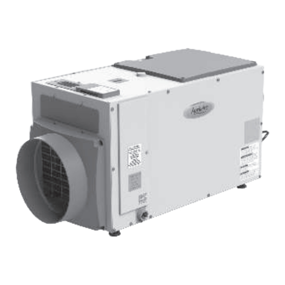
- Page 1 INSTALLATION AND OWNER’S MANUAL Model E080 & E100 Dehumidifi er INSTALLED BY: INSTALLER PHONE: DATE INSTALLED: Product Info & Digital Manual PLEASE LEAVE THIS MANUAL WITH THE DEHUMIDIFIER OWNER 1 English...
-
Page 2: Table Of Contents
Table of Contents Safety Instructions . . . . . . . . . . . . . . . . . . . . . . . . . . . . . . . . . . . . . . . . 3 Wiring . -
Page 3: Safety Instructions
SAFETY INSTRUCTIONS WHOLE HOME DEHUMIDIFICATION Be sure to read and understand all safety precautions The AprilAire Dehumidifier controls the humidity ® and instructions before installing and operating the unit . level in your entire home . A powerful blower inside the dehumidifier draws air into the cabinet where it is filtered before having moisture removed . -
Page 4: Energy Savings Tips
2 . Use the ON/OFF Button (see Figure 2) on the control ENERGY SAVINGS TIPS panel to turn the dehumidifier ON . The first press of a button will turn on the display light, so if ENERGY SAVINGS TIP #1: the display was dark, you might need to press it Adjust the humidity setting to be as high as is again . -
Page 5: Cleaning The Drain
CLEANING THE DRAIN With the filter door on the drain side of the dehumidifier removed, reach in and pull out the drain insert using the finger loop (see Figure 6) . 90-2607 Figure 6: Drain Cleaning 1 - Drain Insert OTE: 2 . -
Page 6: Specifications
SPECIFICATIONS Model E080 Model E100 Unit Weight 63 lbs . 64 lbs . Capacity 80 pints per day @ 185 CFM 100 pints per day @ 280 CFM 80°F, 60% RH Conditions Power 5 . 1 A operating current 6 . 9 A operating current 115 VAC, Single Phase, 60 Hz Dehumidification: 50°F–104°F, 40°F dew point minimum... -
Page 7: Repositioning The Control For The Application
REPOSITIONING THE CONTROL FOR THE INSTALLING THE DUCT COLLARS APPLICATION • Use the screws in the parts bag to attach the duct collars to the inlet and outlet of the dehumidifier . Locate the onboard control panel on the top of the The outlet collar has a backflow damper . -
Page 8: Installing The Dehumidifier
INSTALLING THE DEHUMIDIFIER LEVELING AND RAISING THE DEHUMIDIFIER DEHUMIDIFIER LOCATION The feet can be adjusted to level the unit and accommodate drain fittings and condensate pans as required . Use the top-mounted bubble level to • Electrical service access and drain cleaning will adjust the feet until the bubble is within the outer circle require the removal of the electrical service side (see Figure 13) . -
Page 9: Installing The Drain
• Install a tee or three-way elbow at the dehumidifier (WC) for Model E080 and 0 . 6 " WC for Models E100/E100H . outlet with a small, capped vertical tube (do not Measure the system pressure when the HVAC fan is cement cap in place) to allow for cleaner to be operating at the highest airflow (speed) setting . -
Page 10: Ducting The Dehumidifier Inlet And Outlet To The Hvac System
5 - Air is Pulled from the Main Supply Duct 15 - 10" Diameter Insulated Duct Both Sides 6 - Model E080 0 . 4 " WC Maximum 16 - 24" Minimum 7 - Model E100H 0 . 6 " WC Maximum... -
Page 11: Ducting The Dehumidifier Outlet To The Hvac
DUCTING THE DEHUMIDIFIER OUTLET TO THE HVAC SYSTEM WITH DEDICATED DEHUMIDIFIER INLET REGISTER • To direct dehumidified air away from a potentially wet AC coil: − Duct to the supply side of the HVAC system for air handler applications where air is pulled through the AC coil (see Figure 16) . -
Page 12: Wiring To The Hvac System
NC/NO switch in the to access this feature . NC position . If using the AprilAire Model 76 as a remote control, wire to the {+ - A B} terminals . Refer to the installation instructions for the control being used for wiring details . -
Page 13: Ventilation
90-1857 Figure 22: Float Switch Wiring 1 - Normal Closed 90-1898 Float Switch Figure 24: External Control Ventilation Installation 1 - Air is Pulled 3 - 6' Minimum VENTILATION from Outside 4 - Normally Closed 2 - HVAC/Furnace Vent Damper The dehumidifier can activate a normally closed damper to bring in outdoor air through a fresh air 2 . -
Page 14: Zoning The Dehumidifier
. Enter the installer setup menu (see page 15) . • 2 – AprilAire Model 6510, 10" Normally Closed damper b . Press the Mode button until the words VENT • 2 – AprilAire Model 6610, 10" Normally Open damper DISABLE appear . -
Page 15: Installer Setup
Plug unit in and turn power switch ON . 2 . The onboard control screen should display OFF . If not OFF, press the ON/OFF button to turn the unit OFF . 90-1875 Figure 28: Whole-Home Primary Zone Installation OTE: 1 - Return from 6 - Supply to If the display backlight is not on, the first button... -
Page 16: Setting Up Remote Control - Crawl Space
SETTING UP REMOTE CONTROL – CRAWL SETTING UP EXTERNAL CONTROL SPACE/SEALED ATTIC If wiring to an external control ( see page 12 for details) press the s or t button to ENABLE . If wiring to a Model 76 for remote control ( see page 17 for details) press the s or t button to ENABLE . -
Page 17: Applying An Rh Offset
APPLYING AN RH OFFSET USING A MODEL 76 AS A REMOTE CONTROL An offset can be applied to the onboard humidity reading to avoid discrepancies with other humidity- Press the ON/OFF Button to turn the dehumidifier measuring devices in the home . Use the s or t button control ON . -
Page 18: Troubleshooting
DIAGNOSTIC CODES immediately after the call has been satisfied . When an external control is installed, the Secondary Zone will be sampled once per hour if there has not been a call for When an error occurs, the Diagnostic Code along with dehumidification from the Primary Zone . - Page 19 Table 1: Diagnostic Codes Diagnostic Code Failure Mode Action Reset Insufficient 6 . Allow the fan and compressor to run for approximately 10-15 Cycle Power Capacity minutes and then enter diagnostic test mode by simultaneously pressing the s button and MODE button for 3 seconds . The LCD will display: •...
- Page 20 . higher than 0 . 4 " outlet side of the dehumidifier . WC for Model E080 or 0 . 6 " WC • Check if backflow damper is blocked or stuck and remove obstruction . for Model E100/ E100H .
- Page 21 Table 2: Troubleshooting Guide (Continued) Symptom Possible Reason Troubleshooting Procedure The ventilation Cycle time has • The damper will not open if the ventilation time has already been met . damper does been met . not open when the HVAC fan is ODT error or •...
-
Page 22: Service Parts
SERVICE PARTS 90-2595 No . Part Description Part No . No . Part Description Part No . EZK Filter, 13 . 5 " x 11 . 8 75" x 0 . 8 75" 5881 Sensor, Low Temperature, Deh 5455 Internal Control Board, Deh 5444 Sensor, High Temperature, Deh 5456... -
Page 23: Limited Warranty
The exclusive obligation of AprilAire under this warranty AprilAire, P . O . Box 1467, Madison, WI 53701 . shall be to supply, without charge, a replacement for any component which is found to be defective within... - Page 24 Internal Use Only 10016378 • B2210022A • 4.22 © 2022 AprilAire | aprilairepartners.com | 800.334.6011 AprilAire reserves the right to change specifications without notice.
Need help?
Do you have a question about the E080 and is the answer not in the manual?
Questions and answers