
Related Manuals for ABB Ability BECL/D.200.16


Summary of Contents for ABB Ability BECL/D.200.16
- Page 1 Product Manual | 13.02.2023 | V 1.5 ABB Ability BECL/D.200.16 Building Edge Control Brandi ng -- Rel eas e 2018-01-01...
-
Page 2: Table Of Contents
Table of Contents Tabl e of C ontents Notes on the instruction manual ......................... 3 Safety ................................. 4 Intended use ........................... 5 Improper use ........................... 5 Target group / Qualifications of personnel ..................5 Cyber security ..........................6 2.4.1 Ports and services for supporting the main functionality ..............7 2.4.2 Anti-Malware Software ........................ -
Page 3: Notes On The Instruction Manual
Please read the manual carefully and observe the instructions and information it contains. Please keep this manual in a safe place. ABB accepts no liability for errors and safety problems due the failure to observe the manual. If you require additional information or have questions about the Building Ecosystem and its applications, please contact ABB or visit our Internet site at: https://buildings.ability.abb... -
Page 4: Safety
However, residual hazards remain. Read and adhere to the safety instructions to prevent hazards of this kind. ABB accepts no liability for damages due to the failure to observe the safety instructions. The following Instructions point to particular hazards involved in the use of the device or provide... -
Page 5: Intended Use
Each use not listed in Chapter 2.1 “Intended use“ on page 5 is deemed improper use and can lead to personal injury and damage to property. ABB is not liable for damages caused by use deemed contrary to the intended use of the device. The associated risk is borne exclusively by the user or operator. -
Page 6: Cyber Security
ABB has formally established cyber security robustness testing as part of the product development process. The following measures are prerequisite for the safe operation of your system. ABB accepts no liability for non-observance. Access control and limitation The careful isolation of the system against unauthorized access is the basis for every protective concept. -
Page 7: Ports And Services For Supporting The Main Functionality
Safety Safety of user accounts Set a strong access password during initial commissioning. Use passwords that you have received from the administrator only for the first login. Keep passwords secret and use a password manager with two-factor login as memory aid, e.g., Keypass. -
Page 8: Anti-Malware Software
Safety 2.4.2 Anti-Malware Software ABB recommends the following applications for repelling and removing malware. Building Ecosystem Configuration Tool McAfee https://www.mcafee.com Microsoft Security Essentials https://de.wikipedia.org/wiki/Microsoft_Security_Essentials Avira https://www.avira.com Clamscan for Win/Mac/OS2/Linux systems https://de.wikipedia.org/wiki/ClamAV Calmwin https://de.wikipedia.org/wiki/ClamAV MetaDefender (used by EPPC) https://www.opswat.com/products/metadefender AVG Anti-Virus https://www.avg.com... -
Page 9: Safety Instructions
Safety Safety instructions Danger - Electric voltage! Electric voltage! Risk of death and fire due to electric voltage of 100 to 240 V. Dangerous currents flow through the body when coming into direct or indirect contact with live components. This can result in electric shock, burns or even death. -
Page 10: Information On Protection Of The Environment
Information on protection of the environment Information on protection of the environment Environment Consider the protection of the environment! Used electric and electronic devices must not be disposed of with household waste. – The device contains valuable raw materials that can be reused. Therefore, dispose of the device at the appropriate collecting facility. -
Page 11: Product Description
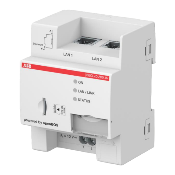
Product description Product description Fig. 1: Product overview The BECL/D.200.16 is a modular DIN-Rail component (MDRC) in Pro M-Design. It is intended for mounting in installation distributors on 35 mm mounting rails. To operate, the device requires a supply voltage US (9 - 14 V DC), which is supplied via an external SELV power adapter. The device can be configured after the direct current supply and at least one LAN cable is connected. -
Page 12: Device Overview
Product description Device overview Fig. 2: Overview of devices [1] Label holder [2] Connection of supply voltage U [3] Micro SD card slot [4] LAN 1 connection (Ethernet) [5] LAN 2 connection (Ethernet) [6] LED ON (green) [7] LED LAN / Link (yellow) [8] LED status (yellow) [9] Reset button (behind label holder) 2CKA001473B5394... -
Page 13: Functions
Description of functions The BECL/D.200.16 is a gateway that offers a safe and local access point via its publication level to the field devices and to the Cloud platform ABB Ability as well as to Clouds of third- party suppliers. - Page 14 Product description Use of middleware: • Uniformize data and independent of technology available for the ontology level • Link with the field layer: a multi-protocol data server to read/write and subscribe to changes of datapoint values coming from the networks •...
-
Page 15: Led Functions
Product description LED Functions The three LEDs on the front of the device have the following functions: LED colour Function Display of operational readiness ■ Off, when there is no supply voltage ■ Flashes slowly during the system startup (1 Hz) ■... -
Page 16: Technical Data
Technical data Technical data Power supply Supply voltage 9 - 14 V DC ±10% (class 2 SELV) or (Power adapter not in scope of delivery) standard 12 V DC / 2 A (class 2 SELV) Power consumption Max. 5 W Surge voltage 800 V Supply terminals... - Page 17 Technical data Classification/approval Protection type IP20 Mode of operation Type 1 (IEC 60730) ■ UL-listed (CDN & US) UL 60730-1 - Automatic electric regulating and control devices - reference Approvals number E499524 ■ CE conformity according to EC guidelines Table 1: Technical data 2CKA001473B5394 │17...
-
Page 18: Dimensional Drawings
Technical data Dimensional drawings Fig. 3: Dimensional drawing (all dimensions are in millimeters) 2CKA001473B5394 │18... -
Page 19: Connection, Installation / Mounting
Connection, installation / mounting Connection, installation / mounting Safety instructions Danger - Electric shock due to short-circuit! Risk of death due to electrical voltage of 100 to 240 V during short-circuit in the low-voltage line. – Low-voltage and 100 - 240 V lines must not be installed together in a flush- mounted box! –... -
Page 20: Mounting
Connection, installation / mounting Mounting The modular DIN rail component must only be installed on mounting rails according to DIN EN 500022 / DIN 60715 TH 35 (including industrial version). Installation To install the device, perform the following steps: – Latch the modular DIN rail component onto the mounting rail. -
Page 21: Electrical Connection
Connection, installation / mounting Electrical connection Fig. 6: Electrical connection Designation of connection Function Supply voltage U − (1) / (external SELV power adaptor necessary) ■ Connection to the IP network via Twisted-Pair cable with RJ45 plug ■ Connection to a standard IP switch or router of the building LAN 1 / LAN 2 ■... -
Page 22: Maintenance
Maintenance Maintenance The device is maintenance-free. In case of damage, e.g. during transport or storage, do not perform repairs. Once the device is opened, the warranty is void. Access to the device must be guaranteed for operation, testing, inspection, maintenance and repairs (according to DIN VDE 0100-520). -
Page 23: Notes
Notes Notes 2CKA001473B5394 │23... -
Page 24: Index
Index Index Anti-malware software ............ 8 Maintenance ..............22 Mounting ................20 Connection, installation / mounting ......19 Notes ................. 23 notes on the instruction manual ........3 Description of functions ..........13 Device overview ............... 12 Dimensional drawings ........... 18 Ports and services for supporting the main functionality.............. - Page 25 Hours: 8:30 am to 5:00 pm (ET), Monday to Friday us-sbs.insidesales@abb.com Technical Support Phone: +1 (877) 226-7767 Hours: 8:30 am to 5:00 pm (ET), Monday to Friday us-sbs.support@abb.com Postal address ABB Inc. 2018 Powers Ferry Road Atlanta, GA 30339, USA new.abb.com/buildings Copyright © 2023 ABB Inc. All rights reserved...