Table of Contents

Related Manuals for Miller Renegade 180


Summary of Contents for Miller Renegade 180
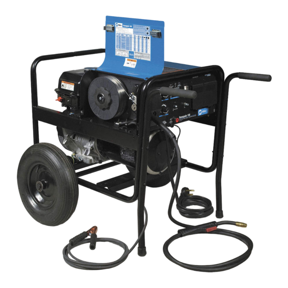
- Page 1 OM-228 042E 2010−04 Processes Processes MIG (GMAW) Welding Flux Cored (FCAW) Welding Description Engine Driven Welding Power Source/ Wire Feeder/Generator Renegade 180 File: Engine Drive Visit our website at www.MillerWelds.com...
- Page 2 We know you don’t have time to do it any other way. That’s why when Niels Miller first started building arc welders in 1929, he made sure his products offered long-lasting value and superior quality.
-
Page 3: Table Of Contents
TABLE OF CONTENTS SECTION 1 − SAFETY PRECAUTIONS − READ BEFORE USING ....... . 1-1. - Page 4 TABLE OF CONTENTS SECTION 8 − MAINTENANCE ............. . . 8-1.
-
Page 5: Section 1 − Safety Precautions − Read Before Using
SECTION 1 − SAFETY PRECAUTIONS − READ BEFORE USING rom_2010−03 Protect yourself and others from injury — read, follow, and save these important safety precautions and operating instructions. 1-1. Symbol Usage DANGER! − Indicates a hazardous situation which, if Indicates special instructions. not avoided, will result in death or serious injury. - Page 6 D Do not weld on closed containers such as tanks, drums, or pipes, FUMES AND GASES can be hazardous. unless they are properly prepared according to AWS F4.1 (see Safety Standards). Welding produces fumes and gases. Breathing these D Do not weld where the atmosphere may contain flammable dust, fumes and gases can be hazardous to your health.
-
Page 7: Engine Hazards
1-3. Engine Hazards EXHAUST SPARKS can cause fire. BATTERY EXPLOSION can injure. D Do not let engine exhaust sparks cause fire. D Always wear a face shield, rubber gloves, and D Use approved engine exhaust spark arrestor in protective clothing when working on a battery. D Stop engine before disconnecting or connect- required areas —... -
Page 8: Hydraulic Hazards
1-4. Hydraulic Hazards D HYDRAULIC FLUID is FLAMMABLE−−do not work on hydraulics HYDRAULIC EQUIPMENT can injure near sparks or flames; do not smoke near hydraulic fluid. or kill. D Reinstall doors, panels, covers, or guards when servicing is D Incorrect installation or operation of this unit finished and before starting unit. -
Page 9: Additional Symbols For Installation, Operation, And Maintenance
HOT METAL from air arc cutting and MOVING PARTS can injure. gouging can cause fire or explosion. D Keep away from moving parts such as fans, D Do not cut or gouge near flammables. belts and rotors. D Watch for fire; keep extinguisher nearby. D Keep all doors, panels, covers, and guards closed and securely in place. -
Page 10: California Proposition 65 Warnings
WELDING WIRE can injure. H.F. RADIATION can cause interference. D Do not press gun trigger until instructed to do D High-frequency (H.F.) can interfere with radio navigation, safety services, computers, and D Do not point gun toward any part of the body, communications equipment. -
Page 11: Principal Safety Standards
1-8. Principal Safety Standards Safety in Welding, Cutting, and Allied Processes, ANSI Standard Z49.1, 25 West 43rd Street, New York, NY 10036 (phone: 212-642-4900, web- from Global Engineering Documents (phone: 1-877-413-5184, website: site: www.ansi.org). www.global.ihs.com). Standard for Fire Prevention During Welding, Cutting, and Other Hot Safe Practices for the Preparation of Containers and Piping for Welding Work, NFPA Standard 51B, from National Fire Protection Association, and Cutting, American Welding Society Standard AWS F4.1, from Glob-... -
Page 12: Section 2 − Consignes De Sécurité − Lire Avant Utilisation
SECTION 2 CONSIGNES DE SÉCURITÉ − LIRE AVANT − UTILISATION fre_rom_2010−03 Pour écarter les risques de blessure pour vous−même et pour autrui — lire, appliquer et ranger en lieu sûr ces consignes relatives aux précautions de sécurité et au mode opératoire. 2-1. - Page 13 D Porter un casque de soudage approuvé muni de verres filtrants LES PIÈCES CHAUDES peuvent approprié pour protéger visage et yeux pour protéger votre visage provoquer des brûlures. et vos yeux pendant le soudage ou pour regarder (voir ANSI Z49.1 et Z87.1 énuméré...
-
Page 14: Dangers Existant En Relation Avec Le Moteur
D Placer les bouteilles debout en les fixant dans un support station- Les CHAMPS ÉLECTROMAGNÉTIQUES (CEM) naire ou dans un porte-bouteilles pour les empêcher de tomber ou peuvent affecter les implants médicaux. de se renverser. D Tenir les bouteilles éloignées des circuits de soudage ou autres D Les porteurs de stimulateurs cardiaques et circuits électriques. -
Page 15: Dangers Liés À L'hydraulique
D Mettre des lunettes de sécurité et des gants, placer un torchon sur LES ÉTINCELLES À L’ÉCHAPPEMENT le bouchon du radiateur. peuvent provoquer un incendie. D Dévisser le bouchon légèrement et laisser la vapeur s’échapper D Empêcher les étincelles d’échappement du avant d’enlever le bouchon. -
Page 16: Dangers Liés À L'air Comprimé
un médecin familiarisé avec ce type de blessure, faute de quoi LES PIÈCES ET LIQUIDES CHAUDS la gangrène pourrait apparaître. peuvent provoquer des brûlures. Les PIÈCES MOBILES peuvent causer D Ne pas toucher les pièces chaudes à main nue des blessures. ni laisser des liquides chauds entrer en contact avec la peau. -
Page 17: Dangers Supplémentaires En Relation Avec L'installation, Le Fonctionnement Et La Maintenance
D Remettre en place les portes, panneaux, recouvrements ou PRESSION D’AIR RÉSIDUELLE dispositifs de protection à la fin des travaux d’entretien et avant ET DES FLEXIBLES QUI FOUETTENT de mettre le moteur en marche. risquent de provoquer des blessures. D Détendre la pression pneumatique des outils et PIÈCES CHAUDES peuvent... -
Page 18: Proposition Californienne 65 Avertissements
D Demander seulement à des personnes qualifiées familiarisées LES CHARGES ÉLECTROSTATI- avec des équipements électroniques de faire fonctionner l’installa- QUES peuvent endommager les tion. circuits imprimés. D L’utilisateur est tenu de faire corriger rapidement par un électricien qualifié les interférences résultant de l’installation. D Établir la connexion avec la barrette de terre avant de manipuler des cartes ou des pièces. -
Page 19: Informations Relatives Aux Cem
2-8. Principales normes de sécurité Safety in Welding, Cutting, and Allied Processes, ANSI Standard Z49.1, 25 West 43rd Street, New York, NY 10036 (phone: 212-642-4900, web- from Global Engineering Documents (phone: 1-877-413-5184, website: site: www.ansi.org). www.global.ihs.com). Standard for Fire Prevention During Welding, Cutting, and Other Hot Safe Practices for the Preparation of Containers and Piping for Welding Work, NFPA Standard 51B, from National Fire Protection Association, and Cutting, American Welding Society Standard AWS F4.1, from Glob-... -
Page 20: Section 3 − Definitions
Complete Parts List available at www. MillerWelds.com SECTION 3 − DEFINITIONS 3-1. Symbol Definitions Read Operator’s Engine Choke Amperes Volts Manual Engine Oil Fuel Circuit Protector Engine Alternating Current Positive Negative Output (AC) Direct Current Protective Earth Hours Time (DC) (Ground) Single-Phase 230 Temperature... -
Page 21: Gun Specifications
Using gasless flux cored wire reduces gun duty cycle. M-15 Feeds .023 To .045 in. (0.6 To 1.1 mm) Hard Or Flux Cored Wires .045 in. (1.1 mm) wire requires liner change to MILLER Part No. 194012 in addition to contact tip change Duty Cycle Rating: 100%: 150 A With CO Shielding Gas;... -
Page 22: Fuel Consumption
Complete Parts List available at www. MillerWelds.com 4-6. Fuel Consumption 1.00 0.80 0.60 0.40 0.20 0.00 Auxiliary Power Kw At 100% Duty Cycle 233 244 4-7. Power Source Duty Cycle Duty cycle is the percentage of 10 minutes that unit can weld at rated load without overheating. -
Page 23: Gun Duty Cycle And Overheating
Complete Parts List available at www. MillerWelds.com 4-8. Gun Duty Cycle And Overheating See Section 4-3. Specifications for amperage rating and duty cycle. Duty Cycle is percentage of 10 minutes that unit can weld at rated load without overheating. NOTICE − Exceeding duty cycle can damage unit and void warranty. - Page 24 Complete Parts List available at www. MillerWelds.com Notes MATERIAL THICKNESS GAUGE OM-228 042 Page 20...
-
Page 25: Section 5 − Installation
Complete Parts List available at www. MillerWelds.com SECTION 5 − INSTALLATION 5-1. Installing Welding Generator Airflow Clearance 18 in. 18 in. (460 mm) (460 mm) Movement 18 in. (460 mm) Shown with standard running gear and optional cylinder rack. 18 in. 18 in. -
Page 26: Grounding Generator When Supplying Building Systems
Complete Parts List available at www. MillerWelds.com 5-3. Grounding Generator When Supplying Building Systems Ground generator to sys- tem earth ground if supply- ing power to a premises (home, shop, farm) wiring system. GND/PE Equipment Grounding Terminal Grounding Cable Use #10 AWG or larger insulated copper wire. -
Page 27: Engine Prestart Checks
Complete Parts List available at www. MillerWelds.com 5-5. Engine Prestart Checks Check all fluids daily. Engine must be cold and on a level surface. Unit is shipped with 10W30 engine oil. Fuel Valve Open valve. Fuel valve is shown in the open 1/2 in position. -
Page 28: Installing Welding Gun
Complete Parts List available at www. MillerWelds.com 5-6. Installing Welding Gun Drive Assembly Gun Securing Knob Gun End Loosen knob. Insert gun end through opening until it bottoms against drive assembly. Tighten knob. Gun Trigger Plug Insert into receptacle, and tighten threaded collar. -
Page 29: Weld Process/Polarity Table
Complete Parts List available at www. MillerWelds.com 5-8. Weld Process/Polarity Table Cable Connections Weld Process Weld Polarity Wire Drive Lead Work Clamp Lead GMAW − Solid wire with shield- DCEP − Reverse polarity Connect to positive (+) out- Connect to negative (−) output ing gas put terminal terminal... -
Page 30: Connecting Single-Phase, 230 Volt Ac Utility Input Power
Complete Parts List available at www. MillerWelds.com 5-10. Connecting Single-Phase, 230 Volt AC Utility Input Power This unit can provide weld output using the engine to power the weld- ing power source/wire feeder OR single−phase 230 volt ac utility power can be used to power the welding power source/wire feeder. -
Page 31: Electrical Service Guide
Complete Parts List available at www. MillerWelds.com 5-11. Electrical Service Guide 60 Hz Single Phase Input Voltage Input Amperes At Rated Output Max Recommended Standard Fuse Rating In Amperes Circuit Breaker , Time-Delay Normal Operating Min Input Conductor Size In AWG Max Recommended Input Conductor Length In Feet (Meters) (20) Min Grounding Conductor Size In AWG... -
Page 32: Threading The Welding Gun
Complete Parts List available at www. MillerWelds.com 5-13. Threading The Welding Gun Tools Needed: 6 in (150 mm) .030/.035 V Groove .030/.035 VK Groove For Solid Wire For Flux Core Or Stainless Wire Stamped .030/.035 V Stamped .030/.035 VK Tighten Pressure Indicator Scale... - Page 33 Complete Parts List available at www. MillerWelds.com Wire Spool Welding Wire Inlet Wire Guide Pressure Adjustment Knob Drive Roll VK = Knurled V Groove (for use with flux core or stainless wire) V = Smooth V Groove (for use with solid wire) The drive roll consists of two differ- ent type grooves.
-
Page 34: Section 6 − Operating The Welding Generator
Complete Parts List available at www. MillerWelds.com SECTION 6 − OPERATING THE WELDING GENERATOR 6-1. Controls (See Section 6-2) 229 573 / 804 971-D OM-228 042 Page 30... -
Page 35: Description Of Controls (See Section 6-1)
Complete Parts List available at www. MillerWelds.com 6-2. Description Of Controls (See Section 6-1) D Set choke. Engine Switch Gun Trigger Receptacle D Turn Engine switch to Start. When en- Use switch to control ignition circuit. Input Power Switch gine starts, allow switch to return to Run Turn switch to Start position when starting en- position. -
Page 36: Weld Parameter Chart
Complete Parts List available at www. MillerWelds.com 6-4. Weld Parameter Chart OM-228 042 Page 32... - Page 37 Complete Parts List available at www. MillerWelds.com OM-228 042 Page 33...
-
Page 38: Section 7 − Operating Auxiliary Equipment
Complete Parts List available at www. MillerWelds.com SECTION 7 − OPERATING AUXILIARY EQUIPMENT 7-1. Generator Power Panel Receptacles 229 573-A NOTICE − Do not parallel the two 120 VAC 2 x (120 V x 10 A) + (240 V x 8 A) = 4.5 kVA/ If unit does not have GFCI recep- duplex receptacles. -
Page 39: Section 8 − Maintenance
Complete Parts List available at www. MillerWelds.com SECTION 8 − MAINTENANCE 8-1. Power Source Routine Maintenance Follow the storage procedure in the engine owner’s manual if the unit will not be used for an extended period. Stop engine before maintaining. See Engine Manual and Maintenance Label Recycle engine for important start-up, service, and storage... -
Page 40: Gun Routine Maintenance
Complete Parts List available at www. MillerWelds.com 8-2. Gun Routine Maintenance Stop engine and dis- connect gun before maintaining. n = Check Z = Change ~ = Clean l = Replace Reference Every Section 8-7 Spool Of Wire ~ Gun Casing ~ Nozzle, n Contact Tip Every 3 Section 8-7... -
Page 41: Changing Drive Roll Or Wire Inlet Guide
Complete Parts List available at www. MillerWelds.com 8-5. Changing Drive Roll Or Wire Inlet Guide Inlet Wire Guide Remove guide by pressing on barbed area or cutting off one end near housing and pulling it out of hole. Push new guide into hole from rear until it snaps in place. -
Page 42: Maintaining Gun
Complete Parts List available at www. MillerWelds.com 8-7. Maintaining Gun Turn off welding power source/wire feeder. Nozzle Contact Tip Adapter Head Tube Cut off wire and disconnect gun from feeder Remove nozzle contact tip and adapter from head tube. Liner Unscrew and remove liner. -
Page 43: Replacing Switch And/Or Head Tube
Complete Parts List available at www. MillerWelds.com 8-8. Replacing Switch And/Or Head Tube Turn off welding power source/wire feeder and dis- connect gun. Handle Locking Nut Switch Housing Handle Vise Head Tube Jam Nut Remove handle locking nut. Remove switch housing. Install new switch and connect leads (po- larity is not important). -
Page 44: Servicing Air Cleaner
Complete Parts List available at www. MillerWelds.com 8-9. Servicing Air Cleaner Stop engine. NOTICE − Do not run engine with- out air cleaner or with dirty element. Precleaner Paper Element Do not wash paper element or clean with compressed air. Remove cover. -
Page 45: Adjusting Engine Speed
Complete Parts List available at www. MillerWelds.com 8-10. Adjusting Engine Speed After tuning engine, check engine speed. See table for proper no load speed. If necessary, adjust speed as follows: Start engine and run until warm. Adjustment Screw To increase speed, turn screw in ±... -
Page 46: Section 9 − Troubleshooting
Complete Parts List available at www. MillerWelds.com SECTION 9 − TROUBLESHOOTING 9-1. Troubleshooting A. Welding Trouble Remedy No weld output or generator power out- Be sure all equipment is disconnected from receptacles when starting unit. put at ac receptacles. Place switch in Single Phase 230 VAC position or start engine and place switch in Engine/Generator posi- AC receptacles provide auxiliary tion. - Page 47 Complete Parts List available at www. MillerWelds.com Trouble Remedy Low output at generator power ac Check engine speed, and adjust if necessary (see Section 8-10 ). Open circuit voltage is reduced as receptacles. engine speed drops. Erratic output at generator power ac Check fuel level.
-
Page 48: Section 10 − Parts List
Complete Parts List available at www. MillerWelds.com Trouble Remedy Engine will not start. Check fuel level (see Section 5-5). Move choke control to correct position (see Section 6-1). Open fuel valve (see Section 5-5). Close fuel valve before moving unit or carburetor may flood and make starting difficult. -
Page 49: Section 11 − Electrical Diagrams
SECTION 11 − ELECTRICAL DIAGRAMS Figure 11-1. Circuit Diagram For Welding Generator OM-228 042 Page 45... -
Page 50: Section 12 − Generator Power Guidelines
SECTION 12 − GENERATOR POWER GUIDELINES The views in this section are intended to be representative of all engine-driven welding generators. Your unit may differ from those shown. 12-1. Selecting Equipment Generator Power Receptacles − Neutral Bonded To Frame 3-Prong Plug From Case Grounded Equipment 2-Prong Plug From Double Insulated Equipment... - Page 51 12-3. Grounding When Supplying Building Systems Equipment Grounding Terminal Grounding Cable Use #10 AWG or larger insulated copper wire. GND/PE Ground Device Use ground device as stated in electrical codes. Ground generator to system earth ground if supplying power to a premises (home, shop, farm) wiring system.
- Page 52 12-5. Approximate Power Requirements For Industrial Motors Industrial Motors Rating Starting Watts Running Watts Split Phase 1/8 HP 1/6 HP 1225 1/4 HP 1600 1/3 HP 2100 1/2 HP 3175 Capacitor Start-Induction Run 1/3 HP 2020 1/2 HP 3075 3/4 HP 4500 1400 1 HP...
- Page 53 12-7. Approximate Power Requirements For Contractor Equipment Contractor Rating Starting Watts Running Watts Hand Drill 1/4 in 3/8 in 1/2 in Circular Saw 6-1/2 in 7-1/4 in 8-1/4 in 1400 1400 Table Saw 9 in 4500 1500 10 in 6300 1800 Band Saw 14 in...
- Page 54 12-8. Power Required To Start Motor Single-Phase Induction Motor Starting Requirements Motor Start Code KVA/HP 10.0 11.2 12.5 14.0 Motor Start Code Running Amperage Motor HP Motor Voltage To find starting amperage: Step 1: Find code and use table to find kVA/HP.
- Page 55 12-10. Typical Connections To Supply Standby Power Have only qualified persons perform these connections according to all applicable codes and safety practices. Properly install and ground this equipment according to its Owner’s Manual and na- Fused tional, state, and local codes. Welding Utility Disconnect...
- Page 56 12-11. Selecting Extension Cord (Use Shortest Cord Possible) Cord Lengths for 120 Volt Loads If unit does not have GFCI receptacles, use GFCI-protected extension cord. Maximum Allowable Cord Length in ft (m) for Conductor Size (AWG)* Current Load (Watts) (Amperes) 350 (106) 225 (68) 137 (42)
-
Page 57: Section 13 − Mig Welding (Gmaw) Guidelines
SECTION 13 − MIG WELDING (GMAW) GUIDELINES mig1 2009−12 13-1. Typical MIG Process Connections Weld current can damage electronic parts in vehicles. Disconnect both battery cables before welding on a vehicle. Place work clamp as close to the weld as possible. Regulator/ Flowmeter Wire Feeder/... - Page 58 13-2. Typical MIG Process Control Settings These settings are guidelines only. Material and wire type, joint design, fitup, position, shielding gas, etc. affect settings. Test welds to be sure they comply to specifications. Material thickness determines weld parameters. 1/8 or 0.125 in. Convert Material Thickness to Amperage (A)
- Page 59 13-3. Holding And Positioning Welding Gun Welding wire is energized when gun trigger is pressed. Before lowering helmet and pressing trigger, be sure wire is no more than 1/2 in. (13 mm) past end of nozzle, and tip of wire is positioned correctly on seam. Hold Gun and Control Gun Trigger Workpiece...
- Page 60 13-4. Conditions That Affect Weld Bead Shape Weld bead shape depends on gun angle, direction of travel, electrode extension (stickout), travel speed, thickness of base metal, wire feed speed (weld current), and voltage. ° Push ° Drag Perpendicular GUN ANGLES AND WELD BEAD PROFILES Short Normal Long...
- Page 61 13-5. Gun Movement During Welding Normally, a single stringer bead is satisfactory for most narrow groove weld joints; however, for wide groove weld joints or bridging across gaps, a weave bead or multiple stringer beads works better. Stringer Bead − Steady Movement Along Seam Weave Bead −...
- Page 62 13-8. Troubleshooting − Excessive Spatter Excessive Spatter − scattering of molten metal particles that cool to solid form near weld bead. S-0636 Possible Causes Corrective Actions Wire feed speed too high. Select lower wire feed speed. Voltage too high. Select lower voltage range. Electrode extension (stickout) too long.
- Page 63 13-11. Troubleshooting − Lack Of Penetration Lack Of Penetration − shallow fusion between weld metal and base metal. Lack of Penetration Good Penetration S-0638 Possible Causes Corrective Actions Improper joint preparation. Material too thick. Joint preparation and design must provide access to bottom of groove while maintaining proper welding wire extension and arc characteristics.
- Page 64 13-14. Troubleshooting − Waviness Of Bead Waviness Of Bead − weld metal that is not parallel and does not cover joint formed by base metal. S-0641 Possible Causes Corrective Actions Welding wire extends too far out of nozzle. Be sure welding wire extends not more than 1/2 in. (13 mm) beyond nozzle. Unsteady hand.
- Page 65 13-16. Common MIG Shielding Gases This is a general chart for common gases and where they are used. Many different combinations (mixtures) of shielding gases have been developed over the years. The most commonly used shielding gases are listed in the following table.
- Page 66 Problem Probable Cause Remedy Welding arc not stable. Wire slipping in drive rolls. Adjust pressure setting on wire feed rolls. Replace worn drive rolls if necessary. Wrong size gun liner or contact tip. Match liner and contact tip to wire size and type. Incorrect voltage setting for selected wire feed speed on Readjust welding parameters.
- Page 67 Effective January 1, 2010 (Equipment with a serial number preface of MA or newer) This limited warranty supersedes all previous Miller warranties and is exclusive with no other Warranty Questions? guarantees or warranties expressed or implied. LIMITED WARRANTY − Subject to the terms and conditions 90 Days —...
- Page 68 Contact the Delivering Carrier to: File a claim for loss or damage during shipment. For assistance in filing or settling claims, contact your distributor and/or equipment manufacturer’s Transportation Department. © ORIGINAL INSTRUCTIONS − PRINTED IN USA 2010 Miller Electric Mfg. Co. 2010−01...
Need help?
Do you have a question about the Renegade 180 and is the answer not in the manual?
Questions and answers
LOST STARTER KEY
Contact a distributor or service agency near you and provide the model name and serial/style number of your Miller Renegade 180. They can assist with obtaining a replacement starter key.
This answer is automatically generated