Table of Contents
Advertisement
Quick Links
Advertisement
Chapters
Table of Contents

Related Manuals for Keysight Technologies B2961B


Summary of Contents for Keysight Technologies B2961B
- Page 1 Keysight B2961B/B2962B Low Noise Power Source User’s Guide...
- Page 2 Notices Copyright Notice U.S. Government Rights Warranty © Keysight Technologies 2020 The Software is “commercial computer soft- THE MATERIAL CONTAINED IN THIS DOCU- ware,” as defined by Federal Acquisition Reg- MENT IS PROVIDED “AS IS,” AND IS SUBJECT No part of this manual may be reproduced in ulation (“FAR”) 2.101.
- Page 3 COMPLIANCE WITH GERMAN NOISE REQUIREMENTS This is to declare that this product is in conformance with the German Regulation on Noise Declaration for Machines (Lärmangabe nach der Maschinenlärminformation-Verordnung -3.GSGV Deutschland). Herstellerbescheinigung • GERÄUSCHEMISSION Lpa < 70 dB am Arbeitsplatz normaler Betrieb nach DIN 45635 T.
- Page 4 In addition, it violates safety standards of design, manufacture, and intended use of the instrument. Keysight Technologies assumes no liability for customer’s failure to comply with these requirements.
- Page 5 Instruments that appear damaged or defective should be made inoperative and secured against unintended operation until they can be repaired by qualified service personnel. Return the instrument to a Keysight Technologies sales or service office for services and repair to ensure that safety features are maintained.
- Page 6 Safety Symbols The general definitions of safety symbols used on equipment or in manuals are listed below. Direct current. Alternating current. Earth ground terminal. Protective conductor terminal. For protection against electrical shock in case of a fault. Used with field wiring terminals to indicate the terminal which must be connected to ground before operating equipment.
- Page 7 The RCM mark is a registered trademark of the Australian Communications Authority. This signifies compliance with the Australian EMC Framework Regulations under the terms of the Radio communications Act. This ISM device complies with Canadian ICES-001. Cet appareil ISM est conforme à la norme NMB-001 du Canada. This is the symbol for an Industrial, Scientific and Medical, Group 1 Class A product.
- Page 8 Power Supply and Measurement Safety Power Supply Safety • This instrument can output high currents and voltages. Make sure that the load or device under test can safely handle the output current and voltage. Also, make sure that the connection leads can safely withstand the expected currents and are insulated for the expected voltages.
- Page 9 The following image is the source and measurement terminals of Keysight B2961B/ B2962B. For the B2961B/B2962B, the High Force, High Sense, and Guard are the same potential. And the Low Force and Low Sense are the same potential.
- Page 10 High Voltage Shock Hazard Keysight B2961B/B2962B can force dangerous voltages (±210 V) at the High Force, Guard, and High Sense terminals. To prevent electric shock hazard, the following safety precautions must be observed during the use of Keysight B2961B/B2962B. Use a three-conductor AC power cable to appliance coupler (inlet) and the instrument to an •...
- Page 11 Gefahr durch Hochspannung Von den Geräten Keysight B2961B/B2962B können Spannungen an den Anschlüssen “High Force”, “Guard” und “High Sense” von bis zu 210 V ausgehen. Um elektrischem Schlag vorzubeugen, ist bei der Benützung der Geräte Keysight B2961B/B2962B folgendes zu beachten.
- Page 12 Danger de choc dû à une haute tension Une tension dangereuse (max. ± pour; 210 Vdc) émanant du dispositif Keysight B2961B/B2962B peut être sortie aux bornes High Force, Guard et High Sense, d'appareil de protection ou de détection. Les précautions suivantes doivent être obserées contre commotion électrique accidentelle.
- Page 13 高電圧感電注意 Keysight B2961B/B2962B High Force Guard High Sense ±210 Vdc • • Interlock • • High Force Guard High Sense • On/Off On/Off • • Interlock • • •...
- Page 14 Product Stewardship Waste Electrical and Electronic Equipment (WEEE) Directive 2002/96/EC • This product complies with the WEEE Directive (2002/96/EC) marking requirements. The affixed label indicates that you must not discard this electrical/ electronic product in domestic household waste. Product Category: With reference to the equipment types in the WEEE directive Annex 1, this product is classified as a “Monitoring and Control instrumentation”...
- Page 15 To get the latest Data Sheet, go to www.keysight.com/find/b2960 and click “Technical Support” and “Specifications”. The information is subject to change without notice due to the future enhancement. The actual screen image on the B2961B/B2962B may be different from the image shown in this manual.
-
Page 17: Table Of Contents
Keysight B2961B/B2962B........ - Page 18 Checking for Errors ..........69 Installing the Keysight B2961B/B2962B ......70 Safety Considerations .
- Page 19 GPIB/USB Interfaces ......... . .95 LAN Interface .
- Page 20 Math Expression Dialog Box ........138 Trace Buffer Setup Dialog Box .
- Page 21 To Return to Factory Shipment Condition ......164 To Apply Initial Settings........164 To Set Beeper .
- Page 22 To Set Source Wait Time ........175 To Set Output Filter .
- Page 23 6 Function Details Limit/Compliance ..........190 To Set Limit .
- Page 24 Resources Used in the Expressions ......207 Trace Buffer ..........209 Program Memory .
-
Page 25: Getting Started
Operation Summary This chapter describes basic operations for Keysight B2961B/B2962B. Before learning the details of B2961B/B2962B, let us briefly cover the use of the B2961B/B2962B. The operations require only B2961B/B2962B and the power cord. To get started with the operations, open the measurement terminals. - Page 26 Getting Started Connecting your DUT If you want to connect your device under test, see “Connecting a DUT” on page Keysight B2961B/B2962B User’s Guide, Edition 1...
-
Page 27: Applying Dc Output
Getting Started Applying DC Output Applying DC Output B2961B/B2962B can be used as a DC current or voltage source. The following procedure configures B2961B/B2962B as a voltage source and applies a voltage of +0.5 V. Step 1. Press the key to display the Single view or Dual view. - Page 28 In this status, changing the setup changes the channel output immediately. Step 6. Disabling the channel Press the Ch 1 switch to disable channel 1. This turns off the switch light. Keysight B2961B/B2962B User’s Guide, Edition 1...
-
Page 29: Applying Waveform Output
Getting Started Applying Waveform Output Applying Waveform Output B2961B/B2962B can be used as a current or voltage waveform generator. The following procedure configures B2961B/B2962B as a voltage waveform generator and applies a sinusoidal wave voltage of 1 V and 1 Hz. -
Page 30: Performing Spot Measurement
Getting Started Performing Spot Measurement Performing Spot Measurement B2961B/B2962B can be used as a DC current and voltage meter. The following procedure measures current and voltage. If you want to apply DC output before starting measurement, set the DC source. -
Page 31: Performing Sweep Measurement
Getting Started Performing Sweep Measurement Performing Sweep Measurement B2961B/B2962B can be used as a DC current/voltage sweep source and meter. The following example applies a staircase sweep voltage and measures current and voltage at each step voltage. Step 1. Press the key to display the Single view. - Page 32 The following example shows the measurement results for a 10 M resistor connected between the High Force and Low Force terminals of channel 1. Step 9. Disabling the channel Press the Ch 1 switch to disable channel 1. This turns off the switch light. Keysight B2961B/B2962B User’s Guide, Edition 1...
-
Page 33: Operation Tips
Getting Started Operation Tips Operation Tips This section introduces key operation and status information on B2961B/B2962B. “Changing the View Mode” • “Editing the Setup” • “Status Information” • Figure 1-1 Changing the View Mode Single Graph B2961B B2962B Dual Single Ch1... - Page 34 Figure 1-3 Status Information Trigger auto High voltage Remote Error LXI LAN status indicator Trigger active Floating Local lockout MOVE/EDIT View mode For details about the status information, see “Status Information” on page 130. Keysight B2961B/B2962B User’s Guide, Edition 1...
-
Page 35: Operation Summary
Getting Started Operation Summary Operation Summary This section summarizes front panel operations on B2961B/B2962B. “Basic Operations” • “Channel Setup” • “Source Setup” • “Measurement Setup” • “Display Setup” • “File Operations” • “Miscellaneous Functions” • “Interface Setup” • “System Setup and Operations”... - Page 36 To switch the EDIT/MOVE status Rotary knob on a setup field To select the setup value Assist keys, rotary knob, or arrow keys To save/recall all setup information of the B2961B/B2962B Config > Save or Recall function keys Table 1-2 Channel Setup...
- Page 37 To select output-off status Config > Source > Connection function keys To enable/disable automatic output ON Config > Source > Connection function keys To enable/disable automatic output OFF Config > Source > Connection function keys Keysight B2961B/B2962B User’s Guide, Edition 1...
- Page 38 File > Save > Config function keys To save a graph screen damp to USB memory Dump Screen assist key on Graph view To load a system setting data from USB memory File > Load > Config function keys Keysight B2961B/B2962B User’s Guide, Edition 1...
- Page 39 Function > Trigger > Initiate/Abort/Immediate function keys Table 1-8 Interface Setup Task Relevant front panel key To specify measurement data elements I/O > Format > Measure function keys To specify math data elements I/O > Format > Math function keys Keysight B2961B/B2962B User’s Guide, Edition 1...
- Page 40 System > Cal/Test > Self-Test function keys To check errors System > Error > Log function keys To clear error log System > Error > Clear function keys To clear time stamp System > Timestamp > Clear function keys Keysight B2961B/B2962B User’s Guide, Edition 1...
- Page 41 System > More > Info. > Date/Time function keys To perform firmware update System > More > Info. > Update > Firmware function keys To perform demonstration System > More > Info. > Demo. function keys Keysight B2961B/B2962B User’s Guide, Edition 1...
- Page 42 Getting Started Operation Summary Keysight B2961B/B2962B User’s Guide, Edition 1...
-
Page 43: Introduction
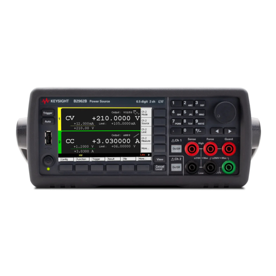
Keysight B2961B/B2962B Low Noise Power Source User’s Guide Introduction Keysight B2961B/B2962B Front View Rear View Power Source Operation and Functions Software and Drivers Accessories Options This chapter describes the basic functions and features of the Keysight B2961B/ B2962B. -
Page 44: Keysight B2961B/B2962B
B2961B/B2962B also supports several functions, such as arbitrary waveform generation, pulse output, sweep output, trace buffer, math expressions, and graph plot. Hence, B2961B/B2962B can be used as a DC (constant) voltage/current source, sweep voltage/current source, pulse generator, arbitrary waveform generator, and multimeter. -
Page 45: Front View
Introduction Front View Front View This section describes the front view of the Keysight B2961B/B2962B. Standby switch • Turns the instrument on or off. When the power is on, the LED below the switch is turned green. Display • Displays the source setup, measurement result, status information, etc. For details, see Chapter 4, “Front Panel Reference.”... - Page 46 Cancel / Local key • Cancels the setup operation if the instrument is in the local status. Returns the instrument to the local status if it is in the remote status. Numeric/alpha keys • Keysight B2961B/B2962B User’s Guide, Edition 1...
- Page 47 Never connect the Guard terminal to any output, including circuit common, chassis ground, or any other guard terminal. Doing so will damage the B2961B/B2962B. Do not apply current to the chassis ground terminal. Doing so will damage the B2961B/B2962B. Keysight B2961B/B2962B User’s Guide, Edition 1...
-
Page 48: Rear View
Introduction Rear View Rear View This section describes the rear view of the Keysight B2961B/B2962B. Channel 2 source/measure terminals • Only on 2-channel models. Terminals for channel 2. High Force, Low Force, High Sense, Low Sense, Guard, and chassis ground. For details, see “Connecting a DUT”... - Page 49 High Force, High Sense et Guard si la borne Interlock est fermée. Serial Number You will need the instrument’s serial number when using the Keysight Technologies telephone assistance program. The serial number label is attached to the bottom of the instrument. Keysight B2961B/B2962B User’s Guide, Edition 1...
-
Page 50: Power Source
Simplified Power Source Circuit Diagram 2-wire connections High Force Current Voltage Monitor Low Force (4½ digit) Chassis ground 4-wire connections High Force Current High Sense Voltage Monitor Low Sense (4½ digit) Low Force Chassis ground Keysight B2961B/B2962B User’s Guide, Edition 1... -
Page 51: Measurement Parameters
Limit value to measure voltage. Limit B2961B/B2962B has a compliance feature that limits the output voltage or current to prevent damage to the device under test. When the channel applies voltage, you can specify the current limit. When the channel applies current, you can specify the voltage limit. -
Page 52: Output And Measurement Ranges
Introduction Power Source Output and Measurement Ranges This section describes typical specifications of the Keysight B2961B/B2962B. Maximum voltage and current: see Figure 2-2. • Maximum power: 31.8 W • Output/measurement value and resolution: see Table 2-2 Table 2-6. • Figure 2-2... - Page 53 21 V 0 |I| 1.515 A 200 V 50 s t 2.5 ms 0 |I| 1.05 A 180 V 50 s t 10 ms Keysight B2961B/B2962B User’s Guide, Edition 1...
- Page 54 Maximum duty cycle is 99.9999 % for the pulse with 50 s t t , and 2.5 % for the pulse with 50 s t 1 ms, 50 s t 2.5 ms, or 50 s t 10 ms. Keysight B2961B/B2962B User’s Guide, Edition 1...
- Page 55 0 < |V2| 6 V I1 + I2 0.625 2.5 A 6 V < |V2| 21 V I1 + I2 2.5 A a. I1: Channel 1 current, I2: Channel 2 current Keysight B2961B/B2962B User’s Guide, Edition 1...
- Page 56 0 |V| 0.212 V 10 V 0 |V| 2.12 V 100 V 20 V 0 |V| 21.2 V 1 mV 200 V 0 |V| 212 V 10 mV Keysight B2961B/B2962B User’s Guide, Edition 1...
-
Page 57: Operation And Functions
2 channels. This is useful for quick checking and debug of the output waveform(s). Easy-to-Use Key Operations Numeric/alpha keys, assist keys, and rotary knob for easy operation • Numeric/alpha keys enable direct input of alphanumeric values. • Assist key guides operation on the front panel. • Keysight B2961B/B2962B User’s Guide, Edition 1... - Page 58 Trace memory for accumulating measurement (or math) result and • collecting their statistics File Operations (USB memory): • Save: System configuration • Measurement/math result • Trace data • Graph screen dump • Load: System configuration • List sweep data • Keysight B2961B/B2962B User’s Guide, Edition 1...
-
Page 59: Program And Interface Capabilities
Program Memory Program memory allows you to store long strings of SCPI command lines once into the B2961B/B2962B's volatile memory and then recall those strings multiple times while the program is executing using a single SCPI command. By storing the command strings in memory, the time that would have been spent sending those same commands over a communication bus is eliminated. - Page 60 5 V power supply pin: • Limited to 600 mA, solid state fuse protected Safety interlock pin: • One active high pin and one active low pin. Activation of both pin enables output voltage > 42 V. Keysight B2961B/B2962B User’s Guide, Edition 1...
-
Page 61: Software And Drivers
Software and Drivers Keysight B2900 Quick I/V Measurement Software • The B2961B/B2962B includes PC-based Keysight B2900 Quick I/V Measurement Software. This powerful software makes it easy to quickly setup and perform I/V measurements and to display the measurement data in a table or graph without the need to perform any programming. -
Page 62: Accessories
Power cord, 1 ea. • USB cable, 1 ea. • Available Accessories For the available accessories for the Keysight B2961B/B2962B, see the catalog Accessories for the Keysight B2900 Precision Instrument Family. To get the latest catalog, go to www.keysight.com/find/b2960 and click “Technical Support”... -
Page 63: Options
Introduction Options Options Table 2-7 lists the options for the Keysight B2961B/B2962B. Table 2-7 Options Option Description Calibration, uncertainties, and guardbanding (not accredited) ANSI Z540 compliant calibration Commercial calibration certificate with test data Keysight B2961B/B2962B User’s Guide, Edition 1... - Page 64 Introduction Options Keysight B2961B/B2962B User’s Guide, Edition 1...
- Page 65 Connecting to the Interfaces Communicating Over the LAN Using Digital I/O This chapter describes how to install Keysight B2961B/B2962B and accessories. To avoid electrical shock and instrument damage, turn the instrument off before connecting or disconnecting measurement cable. Mettez la machine hors tension pour fixer le connecteur ou pour retirer le...
- Page 66 Confirm that the On/Off switch does not turn red. • Open the fixture cover or the shielding box access door (open interlock). • Discharge any capacitors connected to a channel. • Warn persons working around the instrument about dangerous conditions. • Keysight B2961B/B2962B User’s Guide, Edition 1...
- Page 67 Ouvrez le couvercle d'appareil ou la protection du boîtier de la porte • d'accès (verrouillage ouvert). Déchargez tous les condensateurs connectés au réseau. • Informez les personnes se trouvant à proximité de l'appareil à propos des • conditions dangereuses. Keysight B2961B/B2962B User’s Guide, Edition 1...
-
Page 68: Inspecting The Shipment
If you suspect any damage, contact your nearest Keysight Sales and Support Office. 2. When you open the boxes that contain the B2961B/B2962B and accessories, check the components against the contents lists attached to the boxes. If anything is missing, contact your nearest Keysight Sales and Support Office. -
Page 69: Checking For Errors
1. Press the More > System > Error > Log function keys. This opens the Error Log dialog box. 2. Check the errors displayed on the dialog box. If no error is detected, “0, No Error” is displayed. 3. Press the OK softkey to close the dialog box. Keysight B2961B/B2962B User’s Guide, Edition 1... -
Page 70: Installing The Keysight B2961B/B2962B
Safety Considerations Refer to the Safety Summary page at the beginning of this guide for general safety information. Before installation or operation, check the B2961B/B2962B and review this guide for safety warnings and instructions. Safety warnings for specific procedures are located at appropriate places throughout this guide. -
Page 71: Connecting The Power Cord
RISQUE DE CHOC ÉLECTRIQUE: le câble d’alimentation fournit la masse du châssis par le biais d’un troisième conducteur. Assurez-vous de connecter la prise d'alimentation de type trois conducteurs avec la broche correcte mise à la terre. Keysight B2961B/B2962B User’s Guide, Edition 1... - Page 72 Plug: IS 1293 and • • • 250 V, 10 A 250 V, 10 A 250 V, 10 A IS 6538, 250 V, 10 A PN: 8121-1655 PN: 8120-4416 PN: 8120-3996 • PN: 8121-1690 • • • Keysight B2961B/B2962B User’s Guide, Edition 1...
- Page 73 If the wrong power cord was shipped with your instrument, contact your nearest Keysight Sales and Support Office. The AC input on the back of your instrument is a universal AC input. It accepts nominal line voltages in the range of 100 to 240 VAC. Keysight B2961B/B2962B User’s Guide, Edition 1...
-
Page 74: Setting The Power Line Frequency
System > Info. > Date/Time function keys. Bench Installation Do not block the air intake at the sides and the exhaust at the rear of the B2961B/ B2962B. Minimum clearances for bench operation are 5 mm along the sides and 100 mm along the back. -
Page 75: Rack Installation
(2U) of space. Remove the front and rear rubber bumpers and the handle before rack mounting the B2961B/B2962B. Do not block the air intake at the sides and the exhaust at the rear of the B2961B/ B2962B. Removing the Bumper Stretch a corner of the rubber bumper and slide it off. -
Page 76: Maintenance
Installation Maintenance Maintenance Maintenance should be performed periodically to keep the Keysight B2961B/ B2962B in good condition. If problems arise, contact your nearest Keysight Sales and Support Office. “Cleaning” • “Self-test” • “Self-calibration” • “Calibration” • Cleaning SHOCK HAZARD: To prevent electric shock, unplug the B2961B/B2962B before cleaning. -
Page 77: Self-Calibration
5. Press the OK key. This starts the self-test. Self-calibration Keysight B2961B/B2962B provides the self-calibration function to maintain the measurement performance. If the environmental temperature changes 3 C or more, perform the self-calibration. This is effective for the accurate measurements by minimizing the effect of thermal drift. -
Page 78: Calibration
It is recommended to perform the calibration once a year at least. For the calibration and adjustments, contact your nearest Keysight Sales and Support Office. Trained service personnel will perform the calibration and adjustments. Keysight B2961B/B2962B User’s Guide, Edition 1... -
Page 79: Connecting A Dut
“Guarding” • Connecting the interlock circuit B2961B/B2962B provides an interlock function to prevent the user from receiving an electrical shock from high voltages over 42 V. If the Digital I/O interlock terminal is open, B2961B/B2962B cannot apply a high voltage. -
Page 80: 2-Wire Connections Or 4-Wire Connections
To specify the connection type (Sensing Type), perform the following procedure. 1. Press the Config > Source > Connection function keys. This opens the Output Connection dialog box. Keysight B2961B/B2962B User’s Guide, Edition 1... -
Page 81: Floating
For the floating status, the following indicator appears on the status information area. And then the Low Force and Low Sense terminals can be connected to the maximum of 250 V. Channel 1 floating status indicator: Channel 2 floating status indicator: Keysight B2961B/B2962B User’s Guide, Edition 1... - Page 82 Utiliser également des accessoires qui sont conformes à la norme IEC 61010-031. Toutes les bornes et les conducteurs prolongés doivent être isolés en utilisant des bouchons d'isolation, des manchons, etc. Keysight B2961B/B2962B User’s Guide, Edition 1...
-
Page 83: Using Test Leads
Installation Connecting a DUT Using Test Leads B2961B/B2962B source/measure terminals use banana jacks. For connecting a DUT, the following test leads are available. Figure 3-5 shows the connections for two-terminal device measurements. Keysight U8201A Combo Test Lead Kit • Couple of test leads, test probes, alligator clips, SMT grabbers, fine-tips test probes, and banana plugs, CAT III 1000 V, 15 A maximum Two kits are required for 4-wire connections. -
Page 84: Using The Low Noise Filter
Installation Connecting a DUT Using the Low Noise Filter The following filters are available for the B2961B/B2962B to apply low-noise and clean output signal. See Figure 3-6 for their top and connector panels. Also see “Output Filter and External Filter” on page 199 for more information. - Page 85 2. Use appropriate cable or test leads to connect the output of the filter. Before connecting the filter, set External Filter State and External Filter Type correctly. If the settings are correct, the B2961B/B2962B can limit the output up to the filter’s maximum voltage/current. However, if the settings are wrong, the B2961B/B2962B cannot limit the output and may damage the filter.
- Page 86 ± 42 V ± 250 V Max High High Sense Force Output Output ±210 V Max Sense Force ± 21 V Max, ± 500 mA Max ± 42 V Max, ± 105 mA Max Keysight B2961B/B2962B User’s Guide, Edition 1...
-
Page 87: Using The N1295A Test Fixture
Keysight N1297A banana to triaxial adapter for 2-wire connections • Triaxial cable, 2 ea. for one 2-wire connection • Connections 1. Attach the banana to triaxial adapter to the B2961B/B2962B source/measure terminals. See Figure 3-7. If there is some space as “Bad connection”, the contact is not enough. -
Page 88: Using The 16442B Test Fixture
Keysight N1297A: 250 V maximum, 200 V maximum for connecting 16442B Keysight N1297B: 250 V maximum, 200 V maximum for connecting 16442B Keysight 16442B: 200 V, 1 A maximum for SMU input Keysight B2961B/B2962B User’s Guide, Edition 1... - Page 89 Installation Connecting a DUT Connections 1. Attach the banana to triaxial adapter to the B2961B/B2962B source/measure terminals. See Figure 3-7. If there is some space as “Bad connection”, the contact is not enough. 2. Connect the triaxial cables between the adapter and the 16442B.
- Page 90 Prepare the N1297A or N1297B interlock cable, and connect it between the B2961B/B2962B Digital I/O connector and the 16442B Intlk connector. B2961B/B2962B can apply a high voltage when the test fixture cover is closed. Hazardous voltage, instrument maximum output voltage may appear at the High Force, High Sense, and Guard terminals if the fixture cover is closed.
-
Page 91: Guarding
Figure 3-11 Guarding High Force Guard Buffer Never connect the Guard terminal to any output, including circuit common, chassis ground, or any other guard terminal. Doing so will damage the B2961B/B2962B. Keysight B2961B/B2962B User’s Guide, Edition 1... -
Page 92: Installing The Interlock Circuit
B2961B/B2962B cannot apply high voltages over 42 V when the Digital I/O interlock terminal is open. To perform high voltage measurements, the B2961B/B2962B interlock terminal must be connected to the interlock circuit installed in the measurement environment such as the shielding box. - Page 93 Figure 3-13 for the LED dimensions (typical). The LED is used as a high voltage indicator which is lit when B2961B/B2962B is in the high voltage output status. 3. Mount a D-sub connector onto your shielding box. 4. Use a wire and short the following pins of the D-sub connector. See...
- Page 94 Dimensions of the LED (Keysight part number 1990-0486) Cathode (-) Anode (+) Units: mm Figure 3-14 Dimensions of the Interlock Switch (Keysight N1254A-402) 10.3 4.75 35.6 Switch off 15.3 10.3 15.9 18.8 C OM 22.2 27.8 Units: mm Keysight B2961B/B2962B User’s Guide, Edition 1...
-
Page 95: Connecting To The Interfaces
Electrostatic discharges greater than 1 kV near the interface connectors may cause the unit to reset and require operator intervention. B2961B/B2962B supports GPIB, LAN, and USB interfaces. All three interfaces are live at power-on. Connect your interface cable to the appropriate interface connector. - Page 96 4. Use the Connection Expert utility from the Keysight IO Libraries Suite to configure the installed GPIB interface card’s parameters. 5. B2961B/B2962B is shipped with its GPIB address set to 23. To view or change the GPIB address, press the More function key, then the I/O > GPIB softkeys.
-
Page 97: Lan Interface
The hostname as well as the IP address can then be used to communicate with the instrument. The front panel display’s LAN indicator will turn green when the LAN port has been configured successfully, or turn red if the configuration fails. Keysight B2961B/B2962B User’s Guide, Edition 1... - Page 98 3. Use the Connection Expert utility from Keysight IO Libraries Suite to add the B2961B/B2962B and verify the connection. To add the instrument, you can request Connection Expert to discover the instrument. If the instrument cannot be found, add the instrument using the instrument’s hostname or IP address.
-
Page 99: Communicating Over The Lan
Communicating Over the LAN Using the Graphical Web Interface Your Keysight B2961B/B2962B has a built-in graphical web interface that lets you control it directly from an Web browser on your computer. Multiple simultaneous connections are allowed, but only from one computer. With additional connections, performance will be reduced. -
Page 100: Using Telnet
Using Telnet The Telnet utility (as well as sockets), is another way to communicate with B2961B/B2962B without using I/O libraries or drivers. In all cases, you must first establish a LAN connection from your computer to the B2961B/B2962B as previously described. - Page 101 To send a device clear, send the string “DCL” to the control socket. When the B2961B/B2962B has finished performing the device clear, it will echo the string “DCL” back to the control socket. Service requests are enabled for control sockets using the Service Request Enable register.
-
Page 102: Using Digital I/O
Installation Using Digital I/O Using Digital I/O B2961B/B2962B has a Digital I/O connector, D-sub 25 pin female, for general purpose input/output (GPIO). It can be used for: Trigger input • Trigger output • Digital signal input/output • Digital signal input •... - Page 103 Current limit: 600 mA (total current to the pins 22, 23, and 25) b. Used for the positive logic. Connected to the pin 25 for the negative logic. c. Used for the negative logic. Connected to the pin 17 for the positive logic. Keysight B2961B/B2962B User’s Guide, Edition 1...
-
Page 104: Accessory For Digital I/O Connector
DIO 9 Interlock terminals If the N1294A-031 adapter is connected to the Digital I/O connector, the Interlock terminals are opened. Then the B2961B/B2962B output voltage is limited to 42 V. To use the interlock function, see “Installing the Interlock Circuit” on page 92 extend the Interlock terminals. -
Page 105: Front Panel Reference
I/O Key Group Display Key Group System Key Group This chapter provides the reference information of the Keysight B2961B/B2962B front panel keys and display. If measurement is not performed properly, check the trigger setting. The trigger type must be set to AUTO, or the trigger count (Count) must be set properly. See “Trigger Parameters”... -
Page 106: Hard Keys And Rotary Knob
• TRIGger acquire timer period (Measure Period): 10 ms (this is automatically • extended if the measurement is not completed.) Trigger delay (Source Delay = Measure Delay): 0 s • Trigger output: Disable • Keysight B2961B/B2962B User’s Guide, Edition 1... - Page 107 9 changes the value of the next digit. If the digit pointer is on the decimal point of a numeric value entry field, turning the knob moves the decimal point if the Immediate V/I Update by Knob setup is OFF. Keysight B2961B/B2962B User’s Guide, Edition 1...
- Page 108 If the field pointer is in the EDIT (green) status on a numeric value entry field, pressing the key changes the pointer to the digit pointer. If the digit pointer is on a digit of a numeric value entry field, pressing the key moves the pointer on the digits. Keysight B2961B/B2962B User’s Guide, Edition 1...
-
Page 109: Display And Assist Keys
Display and Assist Keys Display and Assist Keys Keysight B2961B/B2962B provides several display modes which depend on the model as shown below. The display mode is changed by the View key. Pressing the key changes the mode as shown below. -
Page 110: Dual View
4. Latest measurement data (4½ digit resolution) 5. High capacitance mode indicator (HC) 6. Programmable output resistance indicator 7. External filter indicator 8. Remote sensing (4-wire connection) status indicator 9. Source function. VOLTS or AMPS. Keysight B2961B/B2962B User’s Guide, Edition 1... - Page 111 Ch n Limit Changes the assist keys to the unit keys shown below. pA, nA, A, mA, and A for the current limit V, mV, and V for the voltage limit Keysight B2961B/B2962B User’s Guide, Edition 1...
- Page 112 205. More... Changes the assist keys to Ch 1 assist keys or Ch 2 assist keys. Ch 1 assist keys are effective for channel 1. Ch 2 assist keys are effective for channel 2. Keysight B2961B/B2962B User’s Guide, Edition 1...
-
Page 113: Single View
7. External filter indicator 8. Remote sensing (4-wire connection) status indicator 9. Source function. VOLTS or AMPS. 10. Source shape indicator. DC, waveform, pulse, sweep, or pulsed sweep. DC does not show the indicator. Keysight B2961B/B2962B User’s Guide, Edition 1... - Page 114 V, mV, and V for the voltage limit First, enter or set the limit value by using the numeric/alpha keys, rotary knob, and arrow keys. Then press one of the unit keys to apply the value. Keysight B2961B/B2962B User’s Guide, Edition 1...
- Page 115 Parameters” on page 117, and changes the softkey label to Show Pulse. Show Trigger Displays the trigger setup parameters shown in “Trigger Parameters” on page 125, and changes the softkey label to Hide Trigger. Keysight B2961B/B2962B User’s Guide, Edition 1...
- Page 116 Parameters” on page 117, and changes the softkey label to Show Trigger. More... Changes the assist keys to Assist keys 1. Softkey labels Show XXXX and Hide XXXX are switched by pressing the key. Keysight B2961B/B2962B User’s Guide, Edition 1...
-
Page 117: Function Parameters
Start value of sweep source or arbitrary waveform. Stop: Stop value of sweep source. Points: Number of sweep source steps. Step: Step value of sweep source. End: End value of arbitrary waveform. Delay: Delay time of arbitrary waveform. Keysight B2961B/B2962B User’s Guide, Edition 1... - Page 118 Phase marker value, 0 to 360, in degree. To use the trigger output, set trigger output condition by using SCPI commands. See Keysight B2961B/B2962B SCPI Command Reference. List Sweep When the field pointer is in the EDIT (green) status on the LIST sweep...
- Page 119 USB memory. Highlight a file and press OK to load the data and close the dialog box. (data graph) Displays the shape of the list sweep data selected by the file list (file list) List of the list sweep data file Keysight B2961B/B2962B User’s Guide, Edition 1...
- Page 120 (data graph) Displays the shape of the waveform output (data list) Lists the data index in the left cell, the output value in the center cell, and the trigger output ON/OFF in the right cell. Keysight B2961B/B2962B User’s Guide, Edition 1...
- Page 121 Setting ON enables the trigger output synchronized with the output of the value set to the center cell. To use the trigger output, set trigger output condition by using SCPI commands. See Keysight B2961B/B2962B SCPI Command Reference. Load User Defined Waveform dialog box •...
- Page 122 The following data can be loaded as the waveform data. Comma separated value format, file extension csv • Carriage return or line feed separated value format, file extension txt • Space separated value format in a line, file extension prn • Keysight B2961B/B2962B User’s Guide, Edition 1...
-
Page 123: Optional Parameters
For the available range values, see “Output and Measurement Ranges” on page Output R: Selects the operation mode OFF, CONST (constant), or EMUL (emulation) of the programmable output resistance function. “Programmable Output Resistance” on page 200 for more information. Keysight B2961B/B2962B User’s Guide, Edition 1... -
Page 124: Pulse Parameters
Display and Assist Keys Pulse Parameters B2961B/B2962B can be used as a pulse source, and supports pulsed output and measurement. Pulse ON or OFF can be selected by using the assist keys displayed when the field pointer is in the EDIT (green) status on the Pulse field. -
Page 125: Trigger Parameters
Display and Assist Keys Trigger Parameters The B2961B/B2962B supports the following trigger types for triggering source output and measurement. They are effective for setting triggers easily. The trigger type can be selected by using the assist keys displayed when the field pointer is in the EDIT (green) status on the Trigger field. - Page 126 The Single view setup is given priority over the trigger layer setup on the Trigger Configuration dialog box. Hence, the overlapped parameter values on the dialog box are ignored. Keysight B2961B/B2962B User’s Guide, Edition 1...
-
Page 127: Graph View
9. Cursor data (controlled by the Show Cursors or Hide Cursors assist key) First line Positions and distance (e.g. I1, I2, A) of Y-cursors 1 and 2 Second line Positions and distance (t1, t2, t) of X-cursors 1 and 2 Keysight B2961B/B2962B User’s Guide, Edition 1... - Page 128 Also changes the softkey label to Hide Ch n. Hide Ch n Hides the channel n limit value and changes the softkey label to Ch n Source. In the above descriptions, Ch n indicates Ch 1 or Ch 2. Keysight B2961B/B2962B User’s Guide, Edition 1...
- Page 129 Number of data is 5001 to 10000: [2*(n-1)+1]th data Number of data is 10001 to 25000: [5*(n-1)+1]th data Number of data is 25001 to 50000: [10*(n-1)+1]th data Number of data is 50001 to 100000: [20*(n-1)+1]th data Keysight B2961B/B2962B User’s Guide, Edition 1...
-
Page 130: Status Information
Red indicates abnormal condition. Blinking indicates the LAN identification status. white Display mode: Dual view white Display mode: Single view for channel 1 white Display mode: Single view for channel 2 white Display mode: Graph view Keysight B2961B/B2962B User’s Guide, Edition 1... -
Page 131: Function Keys
Front Panel Reference Function Keys Function Keys Keysight B2961B/B2962B has six function keys below the front panel display, and provides the following softkeys. Function keys 1 Config Channel configuration setup. Displays the softkeys for setting several functions of the channel. See “Config Key Group”... -
Page 132: Config Key Group
Ch 1 specifies channel 1 only. Ch 2 specifies channel 2 only. Common Displays the following softkeys for setting the miscellaneous function. Wait Source and measurement wait time setup. See “Wait Control Dialog Box” on page 136. Keysight B2961B/B2962B User’s Guide, Edition 1... -
Page 133: Output Connection Dialog Box
Save, Recall Saves/recalls all setup information of the B2961B/B2962B. Five storage areas are available in the built-in non-volatile memory (NVRAM) for this purpose. Press the Save or Recall softkey to display the softkeys #1, #2, #3, #4, and #5 used for selecting the storage area. -
Page 134: Output Filter Dialog Box
This field specifies the channel set by this dialog box. External Filter State Use of the filter, ON for use or OFF for non-use External Filter Type Filter type, HC-ULNF, ULNF, or LNF. HC-ULNF: Keysight N1298A high current ultra low noise filter Keysight B2961B/B2962B User’s Guide, Edition 1... -
Page 135: Sweep Dialog Box
FIXED The sweep source channel sets the range specified by the range parameter Source Ranging: FIXED. See “Optional Parameters” on page 123. Keysight B2961B/B2962B User’s Guide, Edition 1... -
Page 136: Output R (Emulation) Dialog Box
If State = ON and Automatic = ON: • wait time = Gain initial wait time + Offset If State = ON and Automatic = OFF: • wait time = Offset If State = OFF: • wait time = 0 Keysight B2961B/B2962B User’s Guide, Edition 1... - Page 137 Front Panel Reference Config Key Group The initial wait time is automatically set by the instrument, and cannot be changed. Keysight B2961B/B2962B User’s Guide, Edition 1...
-
Page 138: Function Key Group
Result key group. See “Result Key Group” on page 143. Math expressions can be defined by using the SCPI commands while the B2961B/B2962B is in the remote mode. For the predefined math expressions, see “Predefined Math Expressions” on page 206. -
Page 139: Trace Buffer Setup Dialog Box
NEVER: Disables the write operation to the trace buffer. NEXT: Enables the write operation until buffer full. Buffer full will change the mode to NEVER. Buffer Size Size of the trace buffer, 1 to 100000 data Keysight B2961B/B2962B User’s Guide, Edition 1... -
Page 140: Trigger Key Group
On a 1-channel model, selecting the device action executes Initiate, Abort, or Immediate for the specified device action. On a 2-channel model, selecting the device action displays the following softkeys for selecting the channel. Selects channels 1 and 2. Ch 1 Selects channel 1 only. Keysight B2961B/B2962B User’s Guide, Edition 1... -
Page 141: Trigger Configuration Dialog Box
Bypass, ON or OFF Bypass = ON enables the bypass only for the first passage to the event detector for the action specified by the Ch, Layer, and Action parameters. Bypass = OFF disables the bypass. Keysight B2961B/B2962B User’s Guide, Edition 1... - Page 142 Trigger output terminal, an internal bus (INT1, INT2), LAN port (LAN), or a digital I/O pin EXTn (n = 1 to 14) If this parameter is ON, B2961B/B2962B sends an output trigger when it changes the trigger state for the action specified by the Ch, Layer, and Action parameters.
-
Page 143: Result Key Group
In the above formula, Vmeas is the voltage measurement data, and Imeas is the current measurement data. For details on using resistance compensation, see “Resistance Compensation” on page 205. Points Number of data points. Keysight B2961B/B2962B User’s Guide, Edition 1... -
Page 144: Trace Statistical Result Dialog Box
Imeas is the current measurement data. For details on using resistance compensation, see “Resistance Compensation” on page 205. Length Data length Mean Mean value Std. Dev. Standard deviation Min. Minimum value Max. Maximum value Keysight B2961B/B2962B User’s Guide, Edition 1... -
Page 145: File Key Group
Path field and the File Name field. This area can be used for selecting a file by highlighting its name. For saving a system setting file, if the file extension is not specified, “.sta” is added automatically. For saving the other data file, “.csv” is added automatically. Keysight B2961B/B2962B User’s Guide, Edition 1... -
Page 146: Program Key Group
Pressing the Program key displays the following softkeys for setting and controlling the program memory. The program memory can be defined by using the SCPI commands while the B2961B/B2962B is in the remote mode. Catalog Displays the Program Catalog dialog box which lists the programs saved in the program memory. -
Page 147: I/O Key Group
Example: USB0::10893::38657::MY12345678::0::INSTR GPIB Displays the GPIB Configuration dialog box used to set the GPIB address of the B2961B/B2962B. This dialog also displays the VISA GPIB connect string. Example: GPIB0::23::INSTR Displays the following softkeys for managing the Digital I/O interface. Keysight B2961B/B2962B User’s Guide, Edition 1... -
Page 148: Data Output Format
4 to byte 1 for the IEEE-754 single precision format, and byte 1 to byte 8 are sent in the order of byte 8 to byte 1 for the IEEE-754 double precision format. Keysight B2961B/B2962B User’s Guide, Edition 1... -
Page 149: Format (Measure) Dialog Box
Trace data. Selects one from the following data elements. MEAN Mean value STD.DEV. Standard deviation MIN. Minimum value MAX. Maximum value PK-PK Peak to peak value Timestamp Timestamp data format. Selects one from the following selections. Keysight B2961B/B2962B User’s Guide, Edition 1... -
Page 150: Lan Configuration Dialog Box
DNS server configuration, AUTO or MANUAL DNS Server IP address of DNS server, primary and secondary, used for the MANUAL DNS server configuration Hostname Host name of this instrument WINS Server IP address of WINS server, primary and secondary Keysight B2961B/B2962B User’s Guide, Edition 1... -
Page 151: Dio Configuration Dialog Box
Mask Value Mask value which indicates the pattern of the un-used bits of the Digital I/O interface The READ assist key is used to read the mask value presently set to the Digital I/O interface. Keysight B2961B/B2962B User’s Guide, Edition 1... - Page 152 Value set to the Digital I/O interface The READ assist key is used to read the value presently set to the Digital I/O interface. The WRITE assist key is used to write the specified value to the Digital I/O interface. Keysight B2961B/B2962B User’s Guide, Edition 1...
-
Page 153: Display Key Group
The present setting is indicated by an asterisk on the softkey label. Remote Displays the following softkeys for enabling or disabling the front panel display when the B2961B/B2962B is in the remote mode. Disables the front panel display. Effective for fast operation. Enables the front panel display. -
Page 154: Display Preference Dialog Box
Stores the trigger mode setting on entering GP-IB remote state, ON or OFF. Saves the trigger mode setting in the non-volatile memory on entering GPIB remote state and restores the saved trigger mode setting when returning to GPIB local mode. Disables this function. Keysight B2961B/B2962B User’s Guide, Edition 1... -
Page 155: System Key Group
50 Hz Specifies the power line frequency 50 Hz. 60 Hz Specifies the power line frequency 60 Hz. Timestamp Displays the following softkeys to clear timestamp. Keysight B2961B/B2962B User’s Guide, Edition 1... - Page 156 Disables the beep and sound. Enables the beep and sound. Language Displays the following softkeys for specifying the B2961B/B2962B remote control command set. The present setting is indicated by an asterisk on the softkey label. Default Specifies the default command set which supports all functions.
- Page 157 Cancel/Local key to cancel. Factory Returns the B2961B/B2962B to the condition when it is shipped from the factory. Pressing this softkey displays a confirmation dialog box. Press the OK softkey to start the initialization, or the Cancel/Local key to cancel.
- Page 158 Front Panel Reference System Key Group Keysight B2961B/B2962B User’s Guide, Edition 1...
-
Page 159: Front Panel Operations
To Use Math Function To Use Trace Buffer To Use Program Memory This chapter explains how to use the Keysight B2961B/B2962B. Turning the instrument on or off Press the standby switch. When the power is on, the LED below the switch is turned green. - Page 160 DC bias output, pulsed bias output, arbitrary waveform output, staircase sweep output, or pulsed sweep output. Press the Auto key. The repeat (continuous) measurement is performed with the DC bias output (of the Source value). Keysight B2961B/B2962B User’s Guide, Edition 1...
-
Page 161: Basic Operations
In this status, the following operations are allowed. The arrow keys are used to move the pointer. The numeric/alpha keys and rotary knob are used to change the value of the digit indicated by the pointer. Keysight B2961B/B2962B User’s Guide, Edition 1... -
Page 162: To Change The Settings On A Dialog Box
Setting in a Field” on page 161. 2. To apply the settings, press Apply. To apply all settings and close the dialog box, press OK. To cancel the setting change, press the Cancel/Local key instead of pressing Apply. Keysight B2961B/B2962B User’s Guide, Edition 1... -
Page 163: To Use Functions Other Than Measurement
“To Enable/Disable Media Transfer Protocol for Easy File Access” • “To Enable/Disable the Function to Restore the Trigger Mode Settings on the • Local State” “To Enable/Disable Source/Limit Real Time Update by Using Digit Pointer and • Knob” Keysight B2961B/B2962B User’s Guide, Edition 1... -
Page 164: To Set Power Frequency
The Date and Time dialog box opens. 3. Set the date and time. 4. To apply the settings, press Apply. To apply the settings and close the dialog box, press OK. To cancel the setting change, press the Cancel/Local key. Keysight B2961B/B2962B User’s Guide, Edition 1... -
Page 165: To Perform Self-Test
To Display Error Message 1. Press the More > System > Error function keys. 2. Press Log. The error message is displayed in the Error Log dialog box. 3. Press OK to close the dialog box. Keysight B2961B/B2962B User’s Guide, Edition 1... -
Page 166: To Clear Error Buffer
The GPIB Configuration dialog box opens. 3. Set the GPIB address. 4. To apply the settings, press Apply. To apply the settings and close the dialog box, press OK. To cancel the setting change, press the Cancel/Local key. Keysight B2961B/B2962B User’s Guide, Edition 1... -
Page 167: To Set Remote Display Mode
2. Set the Easy File Access field to ON (enable) or OFF (disable). 3. To apply the settings and close the dialog box, press OK. To cancel the setting change, press the Cancel/Local key. Keysight B2961B/B2962B User’s Guide, Edition 1... -
Page 168: On The Local State
2. Set the Immediate V/I Update by Knob field to ON (enable) or OFF (disable). 3. To apply the settings and close the dialog box, press OK. To cancel the setting change, press the Cancel/Local key. Keysight B2961B/B2962B User’s Guide, Edition 1... -
Page 169: To Set Source Output
“To Enable or Disable Automatic Output-On Function” • “To Enable or Disable Automatic Output-Off Function” • “To Set Ranging Mode of the Sweep Source” • “To Set Sweep Direction” • “To Set Source Output Value after Sweep” • Keysight B2961B/B2962B User’s Guide, Edition 1... -
Page 170: To Set Source Output Mode
The field pointer moves to the Limit field. 2. Enter the limit value by using the numeric/alpha keys, rotary knob, and arrow keys. 3. Press the rotary knob or assist key to fix the setting value. Keysight B2961B/B2962B User’s Guide, Edition 1... -
Page 171: To Set Output Function
10. Repeat steps 6 to 9 for all parameters. Applying the sweep voltage/current Press the On/Off switch to start the Source value output. Press the Trigger key to perform the specified sweep output and measurement. Keysight B2961B/B2962B User’s Guide, Edition 1... -
Page 172: To Set Output Range
6. For the constant mode: a. Move the field pointer to the resistance value setup field which is right of the Output R field. b. Press the rotary knob to change the pointer status to EDIT. Keysight B2961B/B2962B User’s Guide, Edition 1... -
Page 173: To Set Pulse Output
“List Sweep” on page 197. 1. Press the View key to display the Single view. 2. If Function parameters are not shown, press the Hide XXXX assist key. 3. Move the field pointer to the Function field. Keysight B2961B/B2962B User’s Guide, Edition 1... -
Page 174: To Set Source Output Trigger Parameters
1. Press the View key to display the Single view. 2. Press the Show Trigger assist key to display the Trigger parameters. 3. Move the field pointer to the Trigger field. 4. Press the rotary knob to change the pointer status to EDIT. Keysight B2961B/B2962B User’s Guide, Edition 1... -
Page 175: To Set Source Wait Time
“Output Filter Dialog Box” on page 134. 1. Press the Config > Source > Filter function keys. The Output Filter dialog box opens. 2. Set each parameter. 3. To apply the settings, press Apply. Keysight B2961B/B2962B User’s Guide, Edition 1... -
Page 176: To Set Connection Type
To apply the settings and close the dialog box, press OK. To cancel the setting change, press the Cancel/Local key. To Enable or Disable High Capacitance Mode For details on this function, see “High Capacitance Mode” on page 204. Keysight B2961B/B2962B User’s Guide, Edition 1... -
Page 177: To Enable Or Disable Over Voltage/Current Protection
3. Set HIGH Z (high impedance), NORMAL (normal), or ZERO (zero volt) in the Output-Off State field. 4. To apply the settings, press Apply. To apply the settings and close the dialog box, press OK. To cancel the setting change, press the Cancel/Local key. Keysight B2961B/B2962B User’s Guide, Edition 1... -
Page 178: To Enable Or Disable Automatic Output-On Function
2. In the Ch field, set the channel to which the setting change is applied. 3. Set BEST, AUTO, or FIXED in the Sweep Ranging field. For details, see “Sweep Dialog Box” on page 135. Keysight B2961B/B2962B User’s Guide, Edition 1... -
Page 179: To Set Sweep Direction
3. Set START VALUE or END VALUE in the Output after Sweep field. For details, “Sweep Dialog Box” on page 135. 4. To apply the settings, press Apply. To apply the settings and close the dialog box, press OK. To cancel the setting change, press the Cancel/Local key. Keysight B2961B/B2962B User’s Guide, Edition 1... -
Page 180: To Execute Measurement
The channel starts the specified voltage/current output. While the switch is turned green, the channel continues the output and changes the value immediately if it is changed. 4. Press the Trigger key. The spot measurement is performed. Keysight B2961B/B2962B User’s Guide, Edition 1... -
Page 181: To Stop Measurement
5. Set the sweep source (see “To Set Output Function” on page 171). 6. Press the View key to display the Graph view. 7. Press the On/Off switch for channel 1 or 2 (Ch1 or Ch2). Keysight B2961B/B2962B User’s Guide, Edition 1... -
Page 182: To Set Measurement Trigger Parameters
140. To Set Measurement Wait Time For details on this function, see “Measurement Time” on page 192 “Wait Control Dialog Box” on page 136. 1. Press the Config > Common > Wait function keys. Keysight B2961B/B2962B User’s Guide, Edition 1... -
Page 183: To Enable Or Disable Resistance Compensation
Ch 1: Channel 1 (Ch 1) only Ch 2: Channel 2 (Ch 2) only 3. To enable the resistance compensation, press ON. To disable it, press OFF. To cancel the setting change, press the Cancel/Local key. Keysight B2961B/B2962B User’s Guide, Edition 1... -
Page 184: To Use Math Function
Unit String field. 6. To apply the settings, press Apply. To apply the settings and close the dialog box, press OK. To cancel the setting change, press the Cancel/Local key. Keysight B2961B/B2962B User’s Guide, Edition 1... -
Page 185: To Use Trace Buffer
5. In the Buffer Size field, set the size of the trace buffer (1 to 100000). 6. To apply the settings, press Apply. To apply the settings and close the dialog box, press OK. To cancel the setting change, press the Cancel/Local key. Keysight B2961B/B2962B User’s Guide, Edition 1... -
Page 186: To Display Statistical Data
4. Press OK to close the dialog box. The Length field displays the number of data. The statistical data is displayed in the following fields: Mean: Mean value Std. Dev.: Standard deviation Min.: Minimum value Max.: Maximum value Keysight B2961B/B2962B User’s Guide, Edition 1... -
Page 187: To Use Program Memory
Pauses the execution of the memory program. Step Starts the step execution of the specified memory program. Stop Stops the execution of the memory program. Continue Continues the execution of the memory program presently paused. Keysight B2961B/B2962B User’s Guide, Edition 1... - Page 188 Front Panel Operations To Use Program Memory Keysight B2961B/B2962B User’s Guide, Edition 1...
- Page 189 Automatic Output-ON/OFF Function High Capacitance Mode Resistance Measurement Math Expression Trace Buffer Program Memory Channel Grouping Trigger System File Access Function (Easy File Access) Interlock Function Over Temperature Protection Initial Settings This chapter describes the functions of the Keysight B2961B/B2962B.
-
Page 190: Function Details
Voltage limit • 20 mV (at 0.2 V range) If the current limit value is too low, the channel will require a long settling time. • Positive and negative limits can be set individually. • Keysight B2961B/B2962B User’s Guide, Edition 1... -
Page 191: Ranging Mode
To set the ranging mode for the DC (constant) source operation, see “Optional • Parameters” on page 123. To set the ranging mode for the sweep source operation, see “Sweep Dialog • Box” on page 135. Keysight B2961B/B2962B User’s Guide, Edition 1... -
Page 192: Measurement Time
6-1. This figure shows an example of sweep output. For a bias output, focus the shape of a sweep step only. 1. Source delay The source delay time is defined as the time from trigger to start of a source output. Keysight B2961B/B2962B User’s Guide, Edition 1... - Page 193 To set the delay time and the period, see “Trigger Parameters” on page 125. To set the wait time, see “Wait Control Dialog Box” on page 136. For more information about the trigger setup, see “Trigger Key Group” on page 140. Keysight B2961B/B2962B User’s Guide, Edition 1...
-
Page 194: Pulse Output
(peak) output. However, it is strictly defined as the time from 10 % of peak level at the leading edge to 90 % of peak level at the trailing edge. The available values are 50 s to 100000 s. Keysight B2961B/B2962B User’s Guide, Edition 1... -
Page 195: To Set Pulse Output
Set the Peak value of “Pulse Parameters” on page 124 for the pulsed bias output. Or set the Start, Stop, and Points values of “Function Parameters” on page 117 for the pulsed sweep output. Keysight B2961B/B2962B User’s Guide, Edition 1... -
Page 196: Sweep Output
135. • To set the output condition after sweep, see “Sweep Dialog Box” on page 135. • To set the pulse delay time and the pulse width, see “Pulse Parameters” on • page 124. Keysight B2961B/B2962B User’s Guide, Edition 1... -
Page 197: List Sweep
To set the source output values, use the List Sweep dialog box. See “List Sweep Setup” on page 118. Figure 6-4 shows an example setup of the List Sweep dialog box with an image of the output waveform. Figure 6-4 List Sweep Dialog Box Keysight B2961B/B2962B User’s Guide, Edition 1... -
Page 198: Arbitrary Waveform Output
Fall Time Time Time ARB SINUSOID ARB USER Phase 1/Frequency ARB SQUARE Time Time Time Time Time Peak n: Points Period = 1000 s maximum Start for all waveform Delay Peak Time End Time Keysight B2961B/B2962B User’s Guide, Edition 1... -
Page 199: Output Filter And External Filter
Also the channel can be equipped with an external filter (N1298A/N1298B/ N1298C low noise filter, LNF). By attaching the filter to the output terminal, the B2961B/ B2962B can be used as a high resolution and high speed DC power supply or a DC bias source for high frequency measurement instrument. -
Page 200: Programmable Output Resistance
For examples using this function, see the following documents. Programmable Output Resistance, Using Constant Mode • Programmable Output Resistance, Using VI Emulation Mode • To get them, go to www.keysight.com/find/b2960 and click “Technical Support”. Keysight B2961B/B2962B User’s Guide, Edition 1... -
Page 201: Over Voltage/Current Protection
0 V and sets the output switch to off automatically and immediately when it reaches the limit status. To set the over voltage/current protection, see “Output Connection Dialog Box” on page 133. Keysight B2961B/B2962B User’s Guide, Edition 1... -
Page 202: Output-Off Status
This setting is not applied to the output-off process triggered by the emergency condition such as the over voltage/current protection, interlock open, and over temperature protection. Then the output voltage is immediately set to 0 V and the output switch is set to off. Keysight B2961B/B2962B User’s Guide, Edition 1... -
Page 203: Automatic Output-On/Off Function
If this function is enabled, the channel automatically turns the output OFF immediately when all trigger system changes the status from busy to idle. To set the automatic output ON/OFF function, see “Output Connection Dialog Box” on page 133. Keysight B2961B/B2962B User’s Guide, Edition 1... -
Page 204: High Capacitance Mode
High capacitance mode is available for the following source/measure condition. Operation mode: voltage source and current measurement • Current measurement range: 1 A to 10 A • To set the high capacitance mode, see “Output Connection Dialog Box” on page 133. Keysight B2961B/B2962B User’s Guide, Edition 1... -
Page 205: Resistance Measurement
Function Details Resistance Measurement Resistance Measurement B2961B/B2962B supports resistance measurement. If the measurement parameter is set to resistance OHMS (R), B2961B/B2962B automatically calculates resistance value from measured voltage and current. For performing accurate measurement, B2961B/B2962B provides the compensation function. Resistance Compensation Resistance compensation (R Compen) is effective for performing low resistance measurements accurately. -
Page 206: Math Expression
Function Details Math Expression Math Expression B2961B/B2962B provides a math function for performing calculations using the measurement result data. The calculation result can be displayed and used for the trace statistics. For the predefined math expressions, see “Predefined Math Expressions” on page 206. -
Page 207: Resources Used In The Expressions
Vector (array) variable is used for sweep measurement data. Math operators • The following operators are available. Arithmetic operators: +, -, *, /, ^, see Table 6-3. • Elementary functions: ln, log, sin, cos, tan, exp • Keysight B2961B/B2962B User’s Guide, Edition 1... - Page 208 Arithmetic and Unary Operators Priority of task Operator Description High Parentheses + and Unary plus operator and unary minus operator Exponentiation operator * and / Multiplication operator and division operator + and Additive operator and subtraction operator Keysight B2961B/B2962B User’s Guide, Edition 1...
-
Page 209: Trace Buffer
The statistical data (except for PKPK) of VOLT, CURR, or RES data can be displayed on the Trace Statistical Result dialog box. See “Trace Statistical Result Dialog Box” on page 144 for displaying the data. Keysight B2961B/B2962B User’s Guide, Edition 1... - Page 210 B2961B/B2962B screen. The data can be saved in an USB memory connected to the front panel USB-A connector or can be read by using SCPI commands. Do not forget to save or read the data before turning the B2961B/B2962B off. The trace buffer is cleared by turning the instrument off.
-
Page 211: Program Memory
If frequently used command strings are stored in the program memory, interface/computer activity is minimized. The program memory can be defined by using SCPI commands while B2961B/B2962B is in the remote mode. See Keysight B2961B/B2962B SCPI Command Reference. Number of programs saved in the memory: 100 •... - Page 212 Running Paused Stopped Error to Running to Running Pause to Paused Paused Stopped Step Error to Running to Paused to Running to Paused Stop to Stopped to Stopped Stopped Continue Error to Running Error Keysight B2961B/B2962B User’s Guide, Edition 1...
-
Page 213: Channel Grouping
For the grouped channels, the wait time starts at the timing of the last output change (DC output change or pulse level transition from peak to base) by the last source output channel. Keysight B2961B/B2962B User’s Guide, Edition 1... -
Page 214: Trigger System
Function Details Trigger System Trigger System B2961B/B2962B supports the ARM-TRIGGER model described in 1999 SCPI Command Reference. Operation summary of this trigger model is described below. Also see Figure 6-7. The trigger system can be initiated by pressing the Trigger key on the front panel. - Page 215 1 to 100000 EXT 1-14 INF. (infinity) TRIGGER count + 1 TRIGGER delay INT1-2 INT1-2 Trigger output Trigger output EXT1-14 EXT1-14 before Device action after Device action Device action (Transient or Acquire ) Keysight B2961B/B2962B User’s Guide, Edition 1...
-
Page 216: Trigger Source
Function Details Trigger System Trigger Source B2961B/B2962B supports the following trigger sources. The trigger source must be set to the ARM event and the TRIGGER event individually. AUTO (automatic internal, AINT): Trigger source best suited for the present • operating mode is automatically selected by the internal algorithms. - Page 217 - for voltage or current output - Source delay Source delay Step value Step value Trigger Trigger Acquire device action - for voltage or current measurement - Measure delay Measure delay Measure Measure Trigger Trigger Keysight B2961B/B2962B User’s Guide, Edition 1...
-
Page 218: Trigger Output
Function Details Trigger System Trigger Output B2961B/B2962B can output trigger at the timing of Trigger output shown in Figure 6-7. The trigger output terminal can be selected from the following terminals. Internal bus, INT1, INT2 • LAN port • Digital I/O pin, EXT1, EXT2, EXT3, EXT4, EXT5, EXT6, EXT7, EXT8, EXT9, •... - Page 219 In addition, the trigger outputs are also available for Phase marker of sinusoidal wave and Trigger points of user defined wave by using the terminals which are not assigned to the above trigger outputs. For setting these trigger outputs, see “Function Parameters” on page 117. Keysight B2961B/B2962B User’s Guide, Edition 1...
-
Page 220: File Access Function (Easy File Access)
Readme.html To control the B2961B/B2962B using a PC, it must be installed with Keysight IO Libraries Suite or equivalent. However, it is not required if you do not do remote control or if you use the file access function in manual operation. -
Page 221: Interlock Function
Ouvrir la borne de verrouillage afin que le délivreur de tension ne puisse pas appliquer de tension dangereuse lorsque la borne source/de mesure est à portée de main ou ouverte. Keysight B2961B/B2962B User’s Guide, Edition 1... -
Page 222: Over Temperature Protection
The over temperature protection is effective for preventing damage to a channel from over temperature. If B2961B/B2962B is used in an environment over 30 C, channel outputs are limited to the value less than the maximum value. If a channel output reaches the limit, all channels automatically and immediately set the output to 0 V and set the output switch to off. -
Page 223: Initial Settings
Function Details Initial Settings Initial Settings The B2961B/B2962B is initialized by turning the B2961B/B2962B on, the *RST command, or the device clear. Initial settings are shown in this section. Table 6-6 System Initial Settings Setup item Power on Reset GPIO function... - Page 224 Programmable output resistance (series resistance) Programmable output resistance (shunt resistance) 2 G Programmable output resistance mode list VOLTS External output filter state Not changed External output filter type ULNF Not changed Source mode VOLTS Keysight B2961B/B2962B User’s Guide, Edition 1...
- Page 225 Current protection level Current source auto ranging 100 A Current source range 1 A Current source range lower limit Current source mode Constant current Current sweep points Current sweep start Current sweep stop Current list points Keysight B2961B/B2962B User’s Guide, Edition 1...
- Page 226 ARB exponential current start level ARB exponential current start time ARB exponential current time constant ARB exponential current total time ARB ramp current end level ARB ramp current end time ARB ramp current rise time Keysight B2961B/B2962B User’s Guide, Edition 1...
- Page 227 ARB trapezoidal current rise time ARB trapezoidal current start level ARB trapezoidal current start time ARB triangle current end time ARB triangle current fall time ARB triangle current peak level ARB triangle current rise time Keysight B2961B/B2962B User’s Guide, Edition 1...
- Page 228 ARB ramp voltage start time ARB sinusoidal voltage amplitude ARB sinusoidal voltage frequency 1 mHz ARB sinusoidal voltage offset ARB sinusoidal voltage phase marker output EXT1 ARB sinusoidal voltage phase marker phase 0 degree Keysight B2961B/B2962B User’s Guide, Edition 1...
- Page 229 ARB triangle voltage start time ARB user defined voltage BOS points ARB user defined voltage BOS signal EXT1 ARB user defined voltage BOS state ARB user defined voltage BOS value ARB user defined voltage level Keysight B2961B/B2962B User’s Guide, Edition 1...
- Page 230 100 s ARM delay time ARM bypass Trigger count Trigger source AINT 10 s Trigger timer Trigger delay time Trigger bypass External trigger output EXT1 External trigger output (LAN) LAN0-7 (all) External trigger output enable Keysight B2961B/B2962B User’s Guide, Edition 1...
- Page 231 “WaitingForAcquireTrigger2” “WaitingForTransitionTrigger2” “Measuring2” “Settling2” Delay time Input/output filter string “ALL:5044” Input/output status Input detection RISE Output drive Output slope Positive Output source “” Output timestamp delta Event logging Circular event logging Event log size Keysight B2961B/B2962B User’s Guide, Edition 1...
- Page 232 Table 6-11 Non-volatile Communication Settings Setup item Factory defaul t setting DHCP Enabled IP address 169.254.5.2 Subnet mask 255.255.0.0 Default gateway 0.0.0.0 Obtain DNS server from DHCP Enabled DNS server 0.0.0.0 WINS server 0.0.0.0 Keysight B2961B/B2962B User’s Guide, Edition 1...
- Page 233 SCPI telnet command interface Enabled SCPI socket command interface Enabled SCPI HiSLIP command interface Enabled Web interface Enabled Command prompt for a Telnet session B2900B> Welcome message for a Telnet session Welcome to Keysight B2900B Series Keysight B2961B/B2962B User’s Guide, Edition 1...
- Page 234 50 Hz Fan control mode Normal V/I Limit for each polarity Immediate V/I update by knob Restore trigger mode on Local External output filter state External output filter type ULNF (ultra low noise filter) Keysight B2961B/B2962B User’s Guide, Edition 1...
- Page 236 This information is subject to change without notice. © Keysight Technologies 2020 Edition 1, December 2020 *B2961-90110* B2961-90110 www.keysight.com...
Need help?
Do you have a question about the B2961B and is the answer not in the manual?
Questions and answers