Table of Contents
Advertisement
Quick Links
Advertisement
Table of Contents

Related Manuals for Megger EZ-ThumpV3


Summary of Contents for Megger EZ-ThumpV3
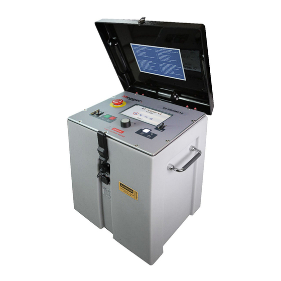
- Page 1 EZTV3-UG-EN-V01 Feb 2022 User Manual Portable Fault Locating System EZ-ThumpV3-3/4/12 kV all V3 models are MULTI SHOT only Read this entire manual before operating Valley Forge Corporate Center 2621 Van Buren Avenue Norristown, PA 19403-2329 U.S.A. 610-676-8500 www.megger.com...
- Page 3 Portable Fault Locating System EZ-ThumpV3-3/4/12kV...
- Page 4 Copyright© 2019 by Megger. All rights reserved. No part of this handbook may be copied by photographic or other means unless Megger have before-hand declared their consent in writing. The content of this handbook is subject to change without notice. Megger cannot be made liable for technical or printing errors or shortcomings of this handbook.
- Page 5 F:+61 (0)2 9397 5911 F: 416 298 0848 Germany India Kingdom of Bahrain Megger Germany Megger (India) Pvt Limited P.O. Box 15777 Dr. Herbert Iann Str. 6 501 Crystal Paradise Mall Office 81, Building 298 96148 Baunach / Germany Off. Veera Desai Road...
-
Page 7: Table Of Contents
Table of Contents 1 SAFETY ............................1 Precautions ..........................1 Warning and Caution Notices..................... 1 Working with the Product ......................2 Operating Personnel ........................2 Repair and Maintenance ......................2 General Cautions and Warnings ....................2 Intended Application ....................... 2 What to Do if Equipment Malfunctions ................. - Page 8 User Modes ..........................18 System Settings ........................19 5 HOW TO PERFORM A TEST ....................24 Detecting and Locating a Cable Fault in a Shielded Medium Voltage Power Cable ....24 Locating a Faulty Cable Segment (Sectionalizing) ..............24 Introduction ........................24 How to Determine the Faulted Section ................25 How to Verify a Faulted Cable Section ................27 Locating a Cable Fault (shielded MV power cable) ..............28 How to Test the Dielectric Strength of the Cable ..............28...
- Page 9 Representative or send to VFCustomerSupport@Megger.com. 2. Examine the equipment for damage received in transit. If damage is discovered, file a claim with the carrier at once and notify Megger, giving a detailed description of the damage. 3. Prior to operation, check for loosened hardware or damage incurred during transit.
- Page 10 EZTV3-UG-EN-V01 Feb 2022...
-
Page 11: Safety
SAFETY SAFETY Precautions This manual contains basic instructions on commissioning and operating the EZ-THUMP 3/4/12kV models. For this reason, it is important to ensure that the manual is always available to authorised and trained personnel. Any personnel who will be using the devices shall read and understand the manual thoroughly. -
Page 12: Working With The Product
Repair and Maintenance Repairs and service must only be done by Megger or Megger authorized service departments. Megger recommends having the equipment serviced and checked once per year at a Megger service location. -
Page 13: What To Do If Equipment Malfunctions
The instruments should only be operated under tempered conditions. Do not operate Megger products in direct contact with humidity, water or near aggressive chemicals nor explosive gases and fumes. -
Page 14: Important Safety Advisory Note - When Working With Hv Surge Generator / Thumper
SAFETY WARNING Dangers when working with HV Special attention and safety awareness are needed when operating HV equipment and especially non-stationary equipment. The regulations VDE 0104 about setting up and operation of electric test equipment, i.e., the corresponding EN 50191 as well as country-specific regulations and standards must be observed. - Page 15 SAFETY 4. The Concentric Neutral (shield of the cable to be tested) of the MV power cable, or a second core of a LV cable to be tested must be bonded to the system grounding point of the power device (see also 1). 5.
-
Page 16: Technical Description
TECHNICAL DESCRIPTION System Description Functional Description The EZ-THUMP 3/4/12kV models are compact fault location system, typically to be used for fault locating of low voltage- and medium voltage power cables. They offer 2 power sources to be operated from. The 2 power sources are AC line voltage and an internal 24V battery system. -
Page 17: Product Models
TECHNICAL DESCRIPTION Product Models There are 4 configurations available for the EZ-THUMP 3/4/12KV MODELS, either with 15 or 50ft (4.5 or 15m) HV/Ground leads and either as a portable version or mounted on an integrated, stainless steel hand truck with large air tires for easy use in open terrain. This manual covers all models of the EZTV3-3/4/12 MODELS. -
Page 18: Scope Of Delivery
HV output cable hard wired (15ft/4.2m or optional 50ft/15m) Safety Grounding cable hard wired AC Power cord Owner’s manual Available Accessories The following accessories* can be ordered from Megger, if required: Accessories Description Item number Elbow adaptor with 14 mm... -
Page 19: Technical Data
TECHNICAL DESCRIPTION Technical Data Parameter Value DC Test voltage 0 to 3/4/or 12 kV depending on model Surge voltage 0 to 3/ 0-4/ 0-12 kV depending on model Source current up to 94mA 3kV unit, up to 36mA 4kV unit, up to 12mA 12kV unit, Insulation measurement 2 kΩ... -
Page 20: Control Elements, Indicators And Connectors
TECHNICAL DESCRIPTION Control Elements, Indicators and Connectors The EZ-THUMP 3/4/12KV MODELS has the following control elements, indicators, and connectors: ❶ ❾ ❷ ❽ ❸ ❹ ❺ ❻ ❼ Element DESCRIPTION Element DESCRIPTION Battery Indicator Bar (green, orange, red) see next page , see next page Jack for connecting external safety device (see next page &... -
Page 21: Power Supply
TECHNICAL DESCRIPTION Power Supply Battery Operation Introduction All EZTV3-3/4/12 MODELS, besides operating of line voltage, are equip- ped with an internal battery, and if fully charged, the units can deliver up to 400 HV discharges (thumps) at full voltage (in each range). This approxima- tely equals 1 hour of thumping (pin-pointing) at full energy at the minimum required charging rate for the maximum voltage (1.5/3, 4 or 12kV). -
Page 22: Charging
TECHNICAL DESCRIPTION NOTE: To protect the battery from a deep discharge, the unit turns off automatically completely or provides an error message if the battery is discharged too low for safe operation, see above. NOTE: To find out whether the battery charge is sufficient for further use of the unit in the field, turn the unit on in battery mode check, the battery symbol should show 4 green bars. -
Page 23: 120/230V Ac Line Operation
TECHNICAL DESCRIPTION 120/230V AC Line Operation As soon as the AC power cord is connected between the receptacle the EZ-THUMP and the AC, the system is operating on AC power, and with the internal battery installed, it is being charged at the same time. If using a power cord other than the one provided, ensure it is rated for at least 250VAC and is 18 AWG or larger. -
Page 24: Setting Up The System
SETTING UP THE SYSTEM WARNING - Safety instructions for setting up The guidelines to maintain occupational safety when operating a non-stationary test system often differ between network operators and it is not uncommon to use National regulations (i.e., the German BGI 5191) Operator must inform him/herself about the guidelines applicable in the area of operation beforehand and comply with specific work... -
Page 25: Connection Diagram
Setting up the System Connection Diagram The following figure shows the simplified connection diagram please review also important safety advisory on pages 4 and 5 Connection Sequence Connect the unit in the following order: Step Description Connect the safety ground lead to a reliable ground (e.g., station-ground, transformer ground rod, do not drive a separate ground rod!). -
Page 26: Operating Instructions
OPERATING INSTRUCTIONS Power on the System Once the "ON / OFF" button is pressed, the system starts up. After start-up, the system is in the 'Ready for the state of operation and the main screen is displayed: The main screen image should show at least the 3 most commonly used fault locating tools - HIPOT - ARM PRELOCATION... -
Page 27: High Voltage Control
OPERATING INSTRUCTIONS The currently selected menu item is identified by a red circle. not selected selected With the aid of the rotary knob, the individual menus can be accessed, and values can be entered. If a selected menu item requires a value to be adjusted, the following dialog is displayed: The value for the parameter can then be adapted by turning the rotary knob and clicking it again to confirm. -
Page 28: Conditions Of The Safety Circuit
OPERATING INSTRUCTIONS and switching operations of the system. Should the safety circuit detect a violation of the monitored thresholds / conditions while in high voltage mode, the system automatically switches the high voltage power supply off and discharges and grounds the HV output. A message will be displayed on the LCD display which must be acknowledged before any operation can be re-activated again. -
Page 29: System Settings
OPERATING INSTRUCTIONS This mode is only recommended to the group of users with extensive experience and expertise in the set-up and operation of the TDR. When selecting this mode, all automatic functions like auto-ranging and auto- gaining, and also the automatic detection of the cable end and the distance to fault have been turned off and must be adjusted manually. - Page 30 OPERATING INSTRUCTIONS Menu item Description >> TDR - Mode AUTOMATIC TDR Operation means that the software utilizes algorithms to Selection determine the end of the cable, the distance to fault, automatically sets the range, the gain, and the pulse width, it also allows user to select which TDR features to make available in both the QUICK-STEPS and EXPERT Modes MANUAL TDR OPERATION means that all automatic functions listed above must be done manually by the user;...
- Page 31 OPERATING INSTRUCTIONS Menu item Description >> Set-up Start Procedure to adjust the start marker "zero" position to the end of the actual length Marker of the HV output cable, for portable EZ-THUMP 3/4/12KV MODELS at the end of the typical 50ft (15m) HV output cable; for vehicle mounted units typically optional cable reels are installed, and the Start Marker is set to the end of the output cable of the HV reel, could be 50ft (15m), 85ft (25m) or 130ft (40m).The procedure is fully automatic and the operator is prompted to perform the required steps:...
- Page 32 OPERATING INSTRUCTIONS Menu item Description Stored Traces Menu item to export or delete all traces which have been stored in the internal memory. Exporting traces requires a USB flash drive plugged into the USB port . The traces are written into a EtrayTraces folder which is automatically created. The data can be viewed with any standard web browser by opening the index.html file which is also located in the EtrayTaces folder.
- Page 33 OPERATING INSTRUCTIONS Menu item Description Customize TDR Menu to configure the features which are available during measurement, for either features QUICK-STEPS mode or EXPERT mode See page 43; not available in Manual Operation, please see page 23 Return By leaving the EXPERT MODE through this menu item, the new settings are saved.
-
Page 34: How To Perform A Test
HOW TO PERFORM A TEST Detecting and Locating a Cable Fault in a Shielded Medium Voltage Power Cable Locating a Faulty Cable Segment (Sectionalizing) Introduction The sectionalizing technique is used to trouble shoot single phase MV distribution loop circuits in order to identify the faulted section, so it can be quickly switched out, the rest of the circuit can be re-energized and the power outage kept to a minimum. -
Page 35: How To Determine The Faulted Section
HOW TO PERFORM A TEST Determine the distance to the fault using the ARM method (red trace, frozen) Determine the number of transformers up to the fault & one beyond it Based on relative position of fault to the 2 closest transformers the faulted cable segment can be identified and easily isolated How to Determine the Faulted Section Step... - Page 36 HOW TO PERFORM A TEST Description Step Select to discharge capacitor (only if measurement start option is set to manual (not required in automatic mode). See page 19. Result: A capacitor discharge (shot) is initiated. If a voltage breakdown takes place, the red fault trace is shown in the display. The red fault marker is automatically set to the position where both traces diverge from each other.
-
Page 37: How To Verify A Faulted Cable Section
HOW TO PERFORM A TEST How to Verify a faulted Cable Section The HIPOT test within the context of Sectionalizing is done to confirm, that the section of cable identified as faulted during the preceding Sectiona- lizing procedure can be verified to be actually faulted. Proceed as follows to perform a HIPOT test after the identified cable section has been isolated at the 2 closest transformers (DC HIPOT test cannot performed with the transformers still connected to the faulted cable section):... -
Page 38: Locating A Cable Fault (Shielded Mv Power Cable)
HOW TO PERFORM A TEST Locating a Cable Fault (shielded MV power cable) How to Test the Dielectric Strength of the Cable A HIPOT/breakdown test is used to test the dielectric strength of a cable under DC HV conditions, and in case the cable fails, provides the break- down voltage. - Page 39 HOW TO PERFORM A TEST Step Description No Flash-over The cable has withstood the applied DC test voltage. In this case no current will be indicated. If required, repeat the test with higher voltage (do not exceed the maximum permissible voltage) Cable not The cable could not be charged while the test voltage was applied.
-
Page 40: How To Pre-Locate The Fault
HOW TO PERFORM A TEST How to Pre-Locate the Fault Arc Reflection Method (ARM) For pre-location of a high resistance MVcable fault the EZ-Thump Models, typically the 12kVmodel, apply the widely approved and well-known ARM (Arc Reflection Method). Locating the fault is accomplished by comparing a reflection image (impedance) taken with a LV pulse (reference trace) to a reflection image (impedance) taken while an arc, ignited by sudden discharge of the charged capacitor, was present at the fault location (fault trace). - Page 41 HOW TO PERFORM A TEST Step Description NOTE: The software provides its best estimate for the cable end. If the trace does not show beyond the flag “open at 950 ft” any significant upwards or downwards reflection, then click to confirm. If there is a substantial reflection beyond this point, turn the rotary to the click and adjust the end marker manually to where the end of the cable is visible, then click to save and confirm.
-
Page 42: Current Decoupling / Surge Pulse (Ice) Not Available In Ez-Thump Family
HOW TO PERFORM A TEST Step Description If required, the surge voltage can be adjusted via the icon, otherwise, the maximum surge voltage is automatically used, if AUTOMATIC VOLTAGE CONTROL has been selected as default. Press the green illuminated “HV ON” button Select to charge the capacitor (only if AUTOMATIC HIGH VOLTAGE RELEASE option is set to Manual. - Page 43 If required, the surge voltage can be adjusted by selecting the icon. Pinpoint the fault within the pre-located area with a surge wave receiver like the Megger Digiphone Plus. For detailed instructions, please refer to the user manual of the surge wave receiver.
-
Page 44: Detecting A Sheath Fault In A Shielded Medium Voltage Cable Or A Ground Fault In An Unshielded, Low Voltage Cable (Both Must Be Directly Buried)
HOW TO PERFORM A TEST Detecting a Sheath Fault in a shielded Medium Voltage Cable or a Ground Fault in an Unshielded, Low Voltage Cable (both must be directly buried) NOTE: The methods described to detect and pinpoint sheath faults in shielded power cables or ground faults in un-shielded cables requires that in both situations the faulted cables are direct buried and not installed in any type of conduit, either PVC... - Page 45 HOW TO PERFORM A TEST Proceed as follows to perform a sheath test: Step Description Select the menu item from the submenu. Confirm the following two notices with Adjust the test voltage and select to confirm the value. Press the green illuminated “HV ON” button Select to start the test (only if AUTOMATIC VOLTAGE RELEASE option is set to Manual.
-
Page 46: How To Pinpoint A Sheath Fault In A Shielded Medium Voltage Cable Or A Ground Fault In An Unshielded Low Voltage Cable (Both Must Be Directly Buried)
If required, you can adjust the pulse voltage by selecting the menu item. Pinpoint the sheath fault with an earth fault locator like the Megger ESG-NT. For detailed instructions, please refer to the user manual of the earth fault locator. -
Page 47: Customize Tdr Features (Applicable To Tdr And Arm Mode)
CUSTOMIZE TDR FEATURES (applicable to TDR and ARM Mode) Introduction As soon as a trace has been recorded and is shown on the display, the operator can access up to 20 TDR Features in order to optimize the trace and display settings. The system configuration allows the user to display each of the 20 features as one of 3 categories, which can be individually selected by user for both modes of operation, QUICK STEPS and EXPERT MODE:... -
Page 48: Customized Tdr Features
CUSTOMIZE TDR FEATURES Customized TDR Features The following table lists and describes all TDR features included in the system Menu item Description Adjusts the gain setting. By doing so, the amplification of the received signal and, thus, the amplitude of the Y-axis can be adjusted. Adjust Gain With an adjustment of the gain setting, the fault trace, if present, is erased and a new “live”... - Page 49 CUSTOMIZE TDR FEATURES Menu item Description Makes an exact copy (blue trace) of the “live” trace. NOTE: This function is very helpful when making a phase Copy trace, makes copy of live comparison on 3 phase MV circuits. trace when superimposing It is also very helpful when just using the TDR several traces...
-
Page 50: Completing The Operation
CUSTOMIZE TDR FEATURES Menu item Description Adjust Pulse Allows manual adjustment of the pulse width. Width Pulse width is automatically selected as a function of cable length Narrow pulses lead to short ranges but at very high resolution. Wide pulses which provide lower resolution must be used when measuring long cables. -
Page 51: Advanced System Settings
ADVANCED SYSTEM SETTINGS How to Edit the Cable List Introduction Cable lists are XML files which are stored in the internal memory and can be imported and exported (see page 21). By default, one cable list with a selection of prevalent cable types is pre-installed on the unit. XML Structure of a Cable List File The following example shows the XML structure of a cable list: <?xml version="1.0"... -
Page 52: How To Edit The Cable List
ADVANCED SYSTEM SETTINGS While the bolded parts must not be changed, there can be an arbitrary number of <cable> elements placed one after another each presenting a cable type. The <cable> element consists of the following mandatory and optional child elements: <attr name="TYPE">... -
Page 53: How To Setup Customer-Specific Tdr Features
ADVANCED SYSTEM SETTINGS Step Action Import the new cable list into the unit. See page 21. Set the new cable list as default cable list. See page 21. How to Setup Customer-Specific TDR Features Thanks to the high level of configurability of the E-TRAY interface, the EZ-THUMP allows for the TDR features in both, "EXPERT MODE"... - Page 54 ADVANCED SYSTEM SETTINGS Step Action Confirm the selection with If required, perform steps 6 to 8 for further options. The adjusted configuration can be shared among your units using the Export and Import functions of the Menu Locate Options menu. EZTV3-UG-EN-V01 Feb 2022...
-
Page 55: How To Use Easyprot Software To Plot Dc Hipot/Sheath Test Data
ADVANCED SYSTEM SETTINGS How to Use EasyPROT Software to Plot DC HIPOT/Sheath Test Data The EZ-THUMP 3/4/12KV MODELS allows recording and graphing of DC test data, either DC HIPOT test data or Sheath test data. Before switching the EZ-Thump on, insert USB drive into front panel. Then start the unit and conduct the particular test. -
Page 56: Care And Maintenance
CARE and MAINTENANCE Maintenance For installation and operation of the equipment it is not necessary to open the enclosure of the instrument. Opening the enclosure will void the warranty and liability of the manufacturer. Connections and connectors must be tested according to all applying standards (international, national and company own). - Page 57 MAINTENANCE EZTV3-UG-EN-V01 Feb 2022...
- Page 58 Appendix 1 Overview of TDR Features See next page for complete chart. EZTV3-UG-EN-V01 Feb 2022...
-
Page 59: Overview Of Tdr Features
OVERVIEW of TDR Features Option Recommended settings Your settings (mark with x) QUICK STEPS mode EXPERT MODE Disa. Simp. Ext. Disa. Simp. Ext. Cable Velocity (option to adjust the QUICK STEPS: simple cable velocity) Expert: simple Xfmr sensitivity (option to adjust the QUICK STEPS: disabled transformer sensitivity) Expert:...
Need help?
Do you have a question about the EZ-ThumpV3 and is the answer not in the manual?
Questions and answers