Table of Contents
Advertisement
Advertisement
Table of Contents

Related Manuals for Megger CM500


Summary of Contents for Megger CM500
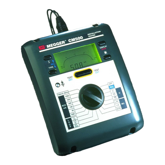
- Page 1 CM500 Multi-Function Installation Tester User Guide...
-
Page 2: Table Of Contents
Contents Safety Warnings Earth Loop Resistance measurement at 15 mA Initial Setup RCD Testing General Description No Trip Tests Features, Controls and Connections Trip Tests Operation Auto Sequence RCD Test Earth Resistance Measurement Backlight Earth Electrode Resistance Measurement Auto shut-off Condition and Warning Indication Switched probe SP2 Test Results, Storage, Deletion and Retrieval... -
Page 3: Safety Warnings
SAFETY WARNINGS Safety Warnings and Precautions must be read and understood before the instrument is used. They must be observed during use. The circuit under test must be switched off, de-energised and isolated before test connections are made when carrying out insulation and continuity tests. -
Page 4: Initial Setup
Initial Setup Read this page before using the CM500. Release the backlight key. Your CM500 has been set up as shown on the label on the Toggle the key to scroll through and display the current front of this User Guide:- setup modes. - Page 5 File displayed as 1 (English) or 2 (as given on the type label on the previous page). From the options given, select: Run. Note:- Language 2 can be changed using the CM500 Setup Type: a:\cm500set and press: Return. Disk supplied.
-
Page 6: General Description
Continuity testing with U.K., European and other International wiring regulations Fast bleeper and standards, the CM500 may be used on all single and three Test lead resistance nulling phase systems with rated voltages up to 300 Volts a.c. rms to Automatic polarity reversal (Setting A) earth/ground. - Page 7 The power cord holder, depress and turn a quarter turn clockwise. Replace and supplied with the CM500 is a test lead that forms part of the re-secure the cover. measuring circuit of the instrument. The overall length of this lead must not be altered.
-
Page 8: Features, Controls And Connections
Features, Controls and Connections Auto Shut-off Operates after 5 minutes of inactivity by the instrument (30 seconds in Bleeper mode) Press key to: Press and TYPE key to: • Select test parameters • Display other test results • Enter test result identification Press and hold key to: •... - Page 9 Single Phase Earth >100 V. Thermal Polarity indication Trip operated Low Battery voltage indication 3 Phase sequence Plug polarity RCD Test Selection Excessive Noise CM500 Connections RCD Type Selection Lead resistance null ‘On’ Over / Under Range Fuse Ruptured CM500 Display...
-
Page 10: Operation
The backlight will briefly operate when indication if a voltage greater than 100 V exists between the the CM500 is switched on. To switch the backlight on, press the earth connection and your finger. key. Press the key again to switch the backlight off. -
Page 11: Polarity Indication
RCD testing. Supply voltage and polarity are displayed. If Setting A is set, the CM500 will automatically switch Line and Press DISPLAY to alternate between supply voltage and Neutral as appropriate, when in any of LOOP, Re (earth) or RCD frequency. -
Page 12: Determining Phase Sequence
Black and Green leads Normal Supply Continuity Testing, Low Resistance and kΩ Measurement Neutral Live The CM500 will measure low resistance from 0.01Ω to 99.9Ω and will automatically change range to kΩ up to 99.9 kΩ using Neutral Open Circuit the 2-wire lead set. -
Page 13: Low Resistance Continuity Measurement
Setting A has been set, a second measurement will be made with the current reversed. To quickly check continuity of a circuit, the CM500 bleeper will sound continuously if the resistance between the leads is less Possible sources of error than 100 Ω. -
Page 14: Insulation Testing And High Resistance Measurement
3-wire lead set method Use of a 3-wire lead set enables all combinations of insulation to The CM500 will test insulation resistance (1 kΩ to 99.9 MΩ) be tested without changing lead connections. between phase, neutral and earth (ground) as required, at the selected voltage. -
Page 15: Loop Impedance Measurement
RESISTANCE - MΩ The CM500 will measure the loop resistance from the supply end of the standard test leads, allowing for their resistance. Insulation Test Voltage... -
Page 16: Bonded Metalwork Testing
Operation (Contd). Press the TEST key. Automatic testing To aid rapid testing, the CM500 can be set to start a test Measured loop value is displayed. automatically when connected to the supply. This may be of On completion of this test, prospective fault current can be use, for example, when using a clip and a probe. -
Page 17: Prospective Short Circuit Current (Pscc)
(Loop) L-L switch position. • Ensuring that the instrument is calibrated. When CM500 measures the loop resistance, it also calculates the PFC. After any loop test, this may be displayed by pressing Earth Loop Resistance measurement at 15 mA the DISPLAY key. -
Page 18: Rcd Testing
Operation (Contd.) RCD Testing Supply voltage is displayed. The CM500 can test the operation of a variety of types of Note:- Though displayed, polarity indications are invalid with Residual Current Devices (RCD), measure the phase to earth the 2- wire lead set and should be ignored loop resistance, and the contact voltage of the installation. - Page 19 Ramp and Auto sequence tests are only available if sensitive’ RCDs are available. the test current is set to 10 mA. The maximum possible Selective or Time delayed RCDs test current (including 5 multiplier) is 1000 mA (300 mA In some cases it may be necessary to have an RCD protecting an individual circuit or group of circuits.
-
Page 20: No Trip Tests
Contact voltage is displayed which is the loop resistance multiplied by the rated RCD current. A high loop Trip Tests resistance will cause the CM500 to display >90 V, and safely The instrument will measure the trip time or trip current of abort the test. - Page 21 150 mA 40 ms test D.C. sensitive RCD rating When an RCD is fitted for personal protection, a test current of RMS currents 150 mA must cause the RCD to trip in less than 40 ms. 10mA 14,1 mA Select the 150 mA 40 ms rotary switch. 30mA 42,4 mA Connect to the supply as detailed below.
-
Page 22: Auto Sequence Rcd Test
, 0˚, 180˚, Setting b: The trip current is displayed with the trip resistance, Fast Trip 0˚ and 180˚. After each trip test, CM500 will wait contact/fault voltage and loop/earth resistance available by for up to 30 seconds for the supply to be switched back on pressing the DISPLAY key. - Page 23 Automatic testing the power plug into a convenient installation socket. If Setting A To aid rapid testing, the CM500 can be set to start a test is selected when using the plug terminated lead set, the polarity automatically when connected to the supply. This may be of of the mains socket is immaterial.
-
Page 24: Earth Resistance Measurement
Insert the test spike. The CM500 can rapidly measure the earth electrode resistance Connect the 20 m earth test lead to the CM500 [4 mm and earth resistance (from 0.01 Ω to 3.00 kΩ) of a TT installation socket (S)] first and then to the test spike. - Page 25 Note:- Though displayed, polarity indications are invalid using the 2-wire test lead set, and should be ignored. 11. Disconnect the red and black leads. Switch off the CM500. 12. Firmly re-connect the earth electrode. 13. Carry out a continuity test between the PE conductor and the earth electrode and confirm that a valid connection has been made.
-
Page 26: Condition And Warning Indication
Touch Pad Check installation or being carried out, or as given in the following table. >100 V wiring to CM500 If the error number is again displayed, switch the instrument to > or < Supply voltage or freq. Supply voltage and and limit ‘Off’, and return the instrument to the manufacturer for service,... -
Page 27: Test Results, Storage, Deletion And Retrieval
Test Result Storage, Deletion and Retrieval Saving Results L-N test, a code, as given in the following table is After a test, the result is displayed on the screen and this may be displayed. This code is used to describe the circuit tested saved with additional information. - Page 28 Note:- CM500 can not respond to a busy signal given by a printer, and therefore waits at the end of each line. To change the Delete all data wait time, see ‘Initial Setup’.
- Page 29 Download to PC currently displayed distribution board. The CM500 has been designed to be used with AVO Select the required circuit number by pressing the RCL PowerSuite for Windows which will accept the test results and up or down keys. The circuit numbers are shown in enable the production of various certificates, including Periodic, numerical order.
-
Page 30: Serial Cable Connections
5) and pin 6 on the CM500, in place of any other connection to pin 6. * If making up a CM500 to PC 9 Way ‘D’ lead, it may be convenient to connect pin 4 to pin 6, enabling the lead to be used either way round. -
Page 31: Specification
Specification EN61557 Operating Range 0,25 Ω to 3,00 kΩ SUPPLY VOLTAGE MEASUREMENT Intrinsic accuracy 25 - 500 V Intrinsic accuracy ± 2% ± 2 digits 0,01 Ω - 9,99 Ω ± 4% ± 0,03Ω SUPPLY FREQUENCY MEASUREMENT 10,0 Ω - 89,9 Ω ±... - Page 32 Specification (Contd.) resistance. Ranges and accuracies are therefore derived from Nominal Supply: 230 V, 50 Hz the previous section. Supply range 100 - 280 V, 45 - 65 Hz LINE EARTH LOOP RESISTANCE MEASUREMENT AT 15 Note:- The maximum possible test current (including the 5I mA (to EN 61557-2) multiplier) is 1000 mA for d.c.
- Page 33 second delay (Selective type only) then execute a Trip test. incremental ramp test. General purpose Test Intrinsic Test Current accuracy I ∆n test for up to 300 ms ±3% I ∆n RAMP RANGE INCREMENT Selective Test I ∆n test for up to 2000 ms 5 - 15 mA 1 mA Note:- The 30 second delay between the automatic...
- Page 34 E.M.C. In accordance with IEC61326 -1 Part 3 - Loop resistance Operational inaccuracies: Refer to www.megger.com ENVIRONMENTAL PROTECTION Part 4 - Resistance of earth connection and equipotential IP40 - The instrument is designed for indoor use, or outdoor bonding (Continuity testing) use if suitably protected.
-
Page 35: Accessories
Accessories Part Number Test and carry case Holds, and supports the instrument to allow ‘hands free‘ operation in use, and protection when not in use. 6420-114 Pouch Holds, and protects the instrument when not in use. 6420-121 Carrying strap Attaches to case or instrument 6220-611 2-wire Test lead set With prods and clips... -
Page 36: Publications
Accessories (Contd.) Publications Part Number User Guide † 6172-258 ‘Testing Electrical Installations’ 6172-129 A detailed account of how to carry out practical testing to BS 7671 (16th Edition IEE Wiring Regulations). ‘A Stitch in Time’ AVTM21-P8B The complete guide to electrical installation testing. ‘Getting Down to Earth’... -
Page 37: Basic And Service Error Calculation
Basic and Service Error Calculation Basic and service errors for Insulation and Resistance ranges The basic error is the maximum inaccuracy of the instrument under ideal conditions, whereas the service error is the maximum inaccuracy taking into effect of battery voltage, temperature, interference, and system voltage and frequency, where applicable. After determining the service error, we can then calculate the measurement range. - Page 38 Basic and Service Error Calculation (Contd.) Max. Max. Max. Max. Max. Max. Limit Limit Indicated Indicated Indicated Indicated Limit Limit Limit Indicated Limit Indicated reading reading reading reading reading reading 70,0 64,2 20,0 17,0 0,10 1,29 1,50 0,03 80,0 73,6 25,0 21,5 0,15...
-
Page 39: Repair And Warranty
MEGGER® spare parts. Consult the personnel. The protection is likely to be impaired if, for example, Appointed Distributor / Agent regarding spare parts, repair the instrument shows visible damage, fails to perform the facilities and advice on the best course of action to take. - Page 40 OTHER TECHNICAL SALES OFFICES Toronto CANADA, Sydney AUSTRALIA, Madrid SPAIN, Mumbai INDIA, and the Kingdom of BAHRAIN. Megger products are distributed in 146 countries worldwide. This instrument is manufactured in the United Kingdom. The company reserves the right to change the specification or design without prior notice.
Need help?
Do you have a question about the CM500 and is the answer not in the manual?
Questions and answers