Trane SYMBIO 700 Troubleshooting Manual
Hide thumbs
Also See for SYMBIO 700:
- Application manual (60 pages) ,
- Integration manual (36 pages) ,
- User manual (20 pages)
Table of Contents
Advertisement
Advertisement
Table of Contents
Troubleshooting

Related Manuals for Trane SYMBIO 700


Summary of Contents for Trane SYMBIO 700
- Page 1 SYMBIO ™ 700 INFORMATION & TROUBLESHOOTING MANUAL APRIL 2021 ~UNOFFICIAL~...
- Page 2 Fluorine and Carbon (HCFCs). Not all refrigerants containing these compounds have the same potential impact to the environment. Trane advocates the responsible handling of all refrigerants-including industry replacements for CFCs and HCFCs such as saturated or unsaturated HFCs and HCFCs.
-
Page 6: Table Of Contents
Symbio™ 700 Unit Controller LEDS ......................18 LED Description Notes ..........................18 Symbio™ 700 Unit LED Functions ......................19 Symbio 700 Factory Connections ....................... 20 Symbio 700 Field Connections ........................23 Odyssey Adapter Board ..........................24 Troubleshooting the Compressor Circuit(s) ....................28 Circuit 1 .............................. - Page 7 When the Outdoor Air Temperature Active ≤ Heat Pump Heating Lockout Setpoint – Active: ..50 When the Outdoor Air Temperature Active > Heat Pump Heating Lockout Setpoint – Active + 5F: .. 50 Symbio 700 Demand Defrost Operation - derived from bench testing ............. 51 First Defrost permit conditions after Power Up..................51 Subsequent Defrosts permit conditions.
- Page 8 Compressor Staging ............................ 66 Cooling Only (Electric Heat) – CVZT & VVZT ..................66 Dual compressor cooling staging (manifold or independent) ............66 Dual unloading compressor cooling staging (10 and 20 ton)............66 Heat Pump – CVZT & VVZT ........................66 Dual compressor cooling staging (manifold or independent) ............
- Page 9 Update Firmware ..........................118 Restart Controller ..........................120 Notes ................................. 121 Notes ................................. 122 Symbio 700 UC Onboard User Interface Menu Structure ............... 123 Symbio 700 UC Onboard User Interface Menu Items ................124 HOME ..............................125 Status ..............................126...
- Page 10 Active Setpoints ..........................126 System .............................. 127 Indoor ............................... 129 Refrigeration ............................. 130 Heat ..............................131 Settings ..............................132 System .............................. 132 Indoor ............................... 133 Refrigeration ............................. 133 Heat ..............................134 Service ..............................135 Diagnostics ............................135 Test..............................135 Statistics Reset ..........................135 Options Modules ..........................
- Page 11 Legacy Electromechanical Condenser with Symbio CV Air Handler ............146 Legacy Reliatel Condenser (Cooling or Heat Pump) with Symbio CV Air Handler ......... 147 - Pairings not in the IOM - ......................... 148 Reliatel Condenser paired with a Symbio SZVAV Air Handler ............149 Symbio Condenser (Cooling Only) with Reliatel SZVAV Air Handler (TR-150 only) ......
- Page 12 TTA1804*C* with TWE1804*B* ......................176 TTA2404*D* with TWE2404*B* ......................177 TTA2404*D* with TWE2404*B* Pressure Curve ................. 178 TTA2404*C* with TWE2404*B* ......................179 TTA3004*C* with TWE3004*B* ......................180 TTA0902*A* with TWE0902*A* ......................181 TTA1202*A* with TWE1202*A* ......................182 TTA1802*D* with TWE180B* ......................183 TTA2402*D* with TWE240B* ......................
-
Page 14: Control Box Layouts
Control Box Layouts Single Fan Condenser Dual Fan Condenser... -
Page 15: Air Handler
Air Handler... -
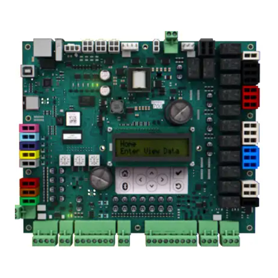
Page 16: Symbio™ 700 Unit Controller (Uc)
Included as base controller on all Symbio™ Condensers. The Symbio 700 controller provides a 2 X 16 backlit LCD display on the middle of the controller. The onboard user interface includes a Bluetooth pair button to pair with the Symbio 700 controller for... -
Page 17: Symbio™ 700 Unit Controller (Uc) Troubleshooting Info
Symbio™ 700 Unit Controller (UC) Troubleshooting Info Note: J19-7 and J21-1 are current limited to 1.1 amp. Note: J2 is not intended to charge mobile phones. Be aware on of wire colors, for some reason Black is 24 VAC Hot and Red is 24 VAC Common. 24 VAC power for the board comes in on J4-1 &... -
Page 18: Symbio™ 700 Unit Controller Leds
Symbio™ 700 Unit Controller LEDS LED Description Notes The LEDs for the internal relays along the right-hand side of the Symbio 700 board illuminate • a solid green color when the relay is energized. The description in the illustration has which output is active. -
Page 19: Symbio™ 700 Unit Led Functions
Symbio™ 700 Unit LED Functions LED 1 – P7-1 (Black) SOLID ON=When output is on, OFF=When output is off LED 2 – P7-3 (Black) SOLID ON=When output is on, OFF=When output is off OFF = Bluetooth radio is not available LED 3 –... -
Page 20: Symbio 700 Factory Connections
Symbio 700 Factory Connections... -
Page 23: Symbio 700 Field Connections
Symbio 700 Field Connections... -
Page 24: Odyssey Adapter Board
Odyssey Adapter Board Electrical Integration board with a series of connectors and traces Eliminates complex harness designs associated with equipment protection features, enables proper power distribution between components in the condenser, and provides connection points between Condenser and Air Handler Included in all Odyssey Symbio™... - Page 25 J1-1 Connected to J5-1 by trace J7-1 Connected to J13-4 by trace J1-2 Connected to eyelet ground by trace J7-2 Connected to eyelet ground by trace J7-3 Connected to J11-4 by trace J2-1 Connected to J5-1 by trace J7-4 Connected to eyelet ground by trace J2-2 Connected to eyelet ground by trace J7-5...
- Page 26 Connected to J4-2 by trace J20-13 Connected to J5-1 by trace J16-3 Connected to eyelet ground by trace J20-14 From Symbio 700 P10-2 J20-15 Connected to J22-6 by trace J17-1 Connected to J21-4 by trace J20-16 Connected to J5-1 by trace...
- Page 27 J21-1 Connected to J5-1 by trace J21-2 Connected to J18-1 by trace J21-3 Connected to J5-1 by trace J21-4 Connected to J17-1 by trace J21-5 Connected to J6-1 by trace J21-6 Connected to eyelet ground by trace J21-7 Connected to J6-3 by trace J21-8 Connected to eyelet ground by trace J21-9...
-
Page 28: Troubleshooting The Compressor Circuit(S)
Troubleshooting the Compressor Circuit(s) Circuit 1 Compressor 1 run command from UC P8-5 to Adapter Board J20-5. Then to Adapter Board J13-1 by board trace. Out to the HPC and back to Adapter Board J13-2. Then to Adapter Board J13-3 by board trace. Out to DTL and back to the Adapter Board J13-4. -
Page 29: Circuit 2
Circuit 2 Compressor 2 run command from UC P9-5 to Adapter Board J20-11. Then to Adapter Board J11-1 by board trace. Out to the HPC and back to Adapter Board J11-2. Then to Adapter Board J11-3 by board trace. Out to DTL and back to the Adapter Board J14-4. Then to Adapter Board J7-3 by board trace, then out to CC2 coil. -
Page 30: Compressor Control Circuit Troubleshooting Tips - Derived From Bench Testing
Compressor Control Circuit Troubleshooting Tips - derived from bench testing. If either the HPC or DTL opens while the compressor is running, the Compressor Contactor will lose its 24 vac and the Aux Switch will open, causing the Symbio Board to generate a “Compressor Proving Trip Diagnostic”... -
Page 31: Compressor Protection - (Hpc, Dtl Or Aux Switch Proving Trip)
Compressor Protection – (HPC, DTL or Aux switch proving trip) Compressor protection operates similar to Reliatel-based solutions, with some minor changes/additions. In most cases, action is taken on a per-circuit basis, but often we have protection devices per compressor. Each compressor output will have a corresponding Compressor Proving input, which will be monitored to determine the state of the compressor contactor (via Auxiliary switch). -
Page 32: Compressor Protection - Low Pressure Cutout Control
For each compressor/circuit, a Normally CLOSED low pressure cutout input will be monitored for equipment protection on the Symbio 700. When a low pressure event is active, the input will become OPEN and diagnostics will be generated as described below. -
Page 33: For Heat Pump Units In Active Mechanical Heating And Outdoor Air Temperature ≥ 0°F
For Heat Pump Units in Active Mechanical Heating and Outdoor Air Temperature ≥ 0°F If a compressor low pressure cutout input opens: All Compressor Outputs on the effected circuit will be immediately Commanded OFF. The “Circuit X LPC Trip” diagnostic point will be annunciated. The Circuit will be disabled for 3 minutes. -
Page 34: Odyssey Relay Board
Odyssey Relay Board Electrical Integration board for Odyssey Air Handlers Includes a set of connectors as well as onboard relay logic to manage variation associated with various air-handler/condenser pairing solutions. Board includes no microcontroller – hardware-based solution only Eliminates complex harnesses and variation for end devices in the Odyssey air handler Included in all Odyssey Symbio Air Handlers Note: J5-2 is current limited to 300ma. - Page 35 The Symbio Air Handler EDC Switch part number is CNT08144. (this switch is Demand Limit in the menu) Switch is shipped in the Normally Open configuration, for Pairing with Electromechanical or Reliatel Condenser, move wire from terminal “H” to terminal “L” on EDC Switch. H-C –...
- Page 36 P1 is used will be on Air Handlers when Digit 15 in the Model Number is D J5-1 connects to J8-2 by a trace in the circuit board. J5-2 is current limited to 300ma, Tech Support recommends not using this terminal for anything at this time.
-
Page 37: Odyssey Options Board - Baymodu001
Odyssey Options Board – BAYMODU001 Optional expansion IO module Multiple instances can be installed with unique addresses, but only the Indoor Options Board is supported for Odyssey at launch. Required for SZVAV/Multi-Speed Symbio Air Handlers and Electric Heat systems when paired with a Symbio ODU Included/added in Odyssey AHU’s... -
Page 38: Indoor Options Module Factory Connections
Indoor Options Module Factory Connections... -
Page 39: J11 Options Module Addressing - Future
J11 Options Module Addressing - future... -
Page 41: Indoor Options Module Communication Troubleshooting
Indoor Options Module Communication Troubleshooting Options Board com voltage is 4.5 to 3.25 VDC, pulsing 30 times a minute. A meter will not show a difference if the field wires are crossed. -
Page 43: Adding Electric Heat To A Symbio Air Handler Paired With A Symbio Condenser
Set the Options Board address to 75. Power up. Add Electric Heat in the Symbio 700 Configuration by using one of the methods below. Using the On-Board menu Go to Home, Utilities, Edit Configuration, Primary Heat for TTA’s, Secondary Heat for TWA’s. -
Page 44: Electric Heat Adapter Harnesses
Electric Heat Adapter Harnesses 43675836 – Symbio Adapter Harness (WIR10632) 43675837 – Legacy Adapter Harness (WIR10690) If you have a Symbio Condenser Paired with a Legacy Air Handler, don't set up the Symbio UI for electric heat because you will get an Options Board Comm Fail. The Relay Board, (which would be in a Symbio 2-Speed Air Handler designed to be paired with a EM Condenser) has a fan interlock built in for electric heat, if you give it 24 vac on J5-7 only, the heat relay clicks but there is no 24 vac output from J3-1, if you give it a G (J5-4) + W1 (J5-7) you get 24 vac out of... -
Page 45: Electric Heat Wiring Diagrams
Electric Heat Wiring Diagrams... -
Page 46: Phase Monitor
Phase Monitor Phase monitors are installed on all 5 to 25 ton products with three-phase power. The main purpose of the phase monitor is to ensure that the scroll compressors are rotating in the proper direction. A green LED on the phase monitor indicates proper phasing. If the input leads are crossed, the phase monitor will sense this and will immediately shut the unit down. -
Page 47: Phase Monitor Wire Connections
Phase Monitor Wire Connections... -
Page 48: Emergency Stop
Emergency Stop Connect a Normally Open field supplied control device to the Symbio 700 (UC) J18-1 & 2. Unit will shut down when switch is closed. -
Page 49: Supply Air Tempering
Supply Air Tempering Supply Air Tempering Operation If the Supply Air Tempering function is configured and the Discharge Air Temperature local sensor is valid, the Space Temperature Control algorithm manages the Supply Air Tempering function to prevent excessively cold discharge air from being supplied from the unit. The sequence for VVZT systems are consistent with CVZT systems, utilizing single-speed, and full airflow operation. -
Page 50: Heat Pump Heating Lockout
Heat Pump Heating Lockout On Heat Pump systems, the user will be able to select a Heat Pump Heating Lockout Setpoint to determine a low outside air temperature limit for heat pump heating operation. There is no enable/disable switch for this function. By default, the Heat Pump Heating Lockout Setpoint will be set to -40F, which essentially disables this function. -
Page 51: Symbio 700 Demand Defrost Operation - Derived From Bench Testing
Subsequent Defrosts permit conditions. Outdoor Air Temp less than 52°, Outdoor Coil Temp less than 33°, The New Initiate DT Value is reached. To view the sensor temperatures using the Symbio 700 On-Board User Interface Press Home, Down Arrow to Status Press the Check Mark, then Down Arrow to System (for outdoor temp) or Refrigeration (for coil temp) Press the Check Mark, then Down Arrow to “Outdoor Air Temperature Arbitrator”... -
Page 52: Defrost Cycle Example
Defrost Cycle Example 12 minutes after exiting the first defrost cycle (after power-up) the OD Air temperature is 40° and the OD coil temperature is 30° (a 10° differential). When the differential reaches 18° (10° X 1.8) the next defrost cycle should begin. The unit runs for 45 minutes at OD Air temperature 40°... -
Page 53: Condenser Defrost (Heat Pumps Only)
Condenser Defrost (Heat Pumps Only) Demand Defrost Control The Symbio 700 Demand Defrost sequence matches the sequence on Reliatel controls, with the exception of changes in diagnostic names: Outdoor coil defrosting occurs only when operating in heating mode with outdoor ambient temperature below 52°F and the outdoor coil temperature below 33°F.The first defrost cycle after power-up is... -
Page 55: Temperature Sensors (Ntc)
Temperature Sensors (NTC) °C (K ohms) -17.22 84.537 2.234 °C (K ohms) -16.67 81.868 2.227 93.33 345.684 Open -16.11 79.291 2.219 -39.44 333.237 2.426 -15.56 76.802 2.211 -38.89 321.274 2.423 -15.00 74.403 2.202 -38.33 309.777 2.420 -14.44 72.087 2.194 -37.78 298.724 2.417 -13.89... - Page 56 °F °C ohms) °F °C ohms) 5.56 24.69 1.779 27.22 9.03 1.186 6.11 24.018 1.764 27.78 8.815 1.171 6.67 23.367 1.750 28.33 8.607 1.156 7.22 22.736 1.736 28.89 8.404 1.142 7.78 22.123 1.721 29.44 8.206 1.127 8.33 21.53 1.706 30.00 8.014 1.112 8.89...
- Page 57 °F °C ohms) °F °C ohms) 48.89 3.743 0.681 71.67 1.659 0.356 49.44 3.665 0.671 72.22 1.629 0.351 50.00 3.589 0.661 72.78 1.599 0.345 50.56 3.514 0.651 73.33 1.57 0.344 51.11 3.442 0.641 73.89 1.541 0.340 51.67 3.371 0.631 74.44 1.512 0.329 52.22...
-
Page 58: Zone Sensor Mode
Zone Sensor Mode °F °C (K ohms) 22.78 0.4416 0.766 Volts DC Ohms System +- 5% Rx1K Switch switch 22.22 0.4610 0.789 0.00 0.00 Short Short 21.67 0.4805 0.812 0.47 2.32 AUTO 21.11 0.5000 0.834 0.82 4.87 COOL AUTO 20.56 0.5195 0.855 1.09... -
Page 59: Zone Sensor Info
If the Odyssey condenser wasn't ordered with a BACnet enabled Symbio 700 UC, Model Number Digit 21 = 1, the only way to get it in the field at this time is to replace the Symbio 700 with a version that has... -
Page 60: Baysens135 / X13790886 / Wiring
BAYSENS135 / X13790886 / Wiring Symbio 700 Feature BAYSENS135* terminal block Description (J19) Position Zone Temperature 2.5 Volt Common Cool Setpoint System / Fan Mode Heating Setpoint COMM + COMM - Ground (24 VAC Common) 24 VAC... -
Page 61: Zone Sensor Averaging
Zone Sensor Averaging When a large zone is being conditioned, it may not be easy to find one place that provides a good typical room temperature all day long. By using multiple sensors, the average temperature can be sensed and provide operation more acceptable for the zone. -
Page 62: Remote Sensor Wiring
Remote Sensor Wiring Using a BAYSENS108 and a BAYSENS077 as an example. -
Page 63: Additional Thermostat / Zone Sensor Info
Symbio 700 (UC) Y1 + X2 nothing will run, not even the indoor fan. Symbio 700 (UC) Y1 + W2 + X2 nothing will run, not even the indoor fan. Y2 before Y1 – Circuit 1 on, Add Y1 after 3 minutes – Circuit 2 on, remove Y2 – Circuit 2 off, remove Y1 –... -
Page 64: Condenser Fan Rotation For Dual Fan Units
Condenser Fan Rotation for Dual Fan Units... -
Page 65: Condenser Fan Staging
Condenser Fan Staging -or- Dual condenser fan - shared airstream manifolded (cooling only) Dual condenser fan - independent airstream dual (cooling only and heat pump) -
Page 66: Compressor Staging
Compressor Staging Cooling Only (Electric Heat) – CVZT & VVZT Dual compressor cooling staging (manifold or independent) Dual unloading compressor cooling staging (10 and 20 ton) Heat Pump – CVZT & VVZT Dual compressor cooling staging (manifold or independent) -
Page 67: Constant Volume/Multi-Speed Fan Space Temperature Control (Cvzt)
Constant Volume/Multi-Speed Fan Space Temperature Control (CVZT) Similar to the Reliatel control system, the Symbio 700 includes a single-loop (space temperature only) control sequence. The sequence is PI-based (proportional, integral) and strives to maintain space temperature within 1F of the Active Cooling and Heating setpoints. -
Page 68: Constant Volume/Multi-Speed Fan Space Temperature Control (Cvzt) Chart
Constant Volume/Multi-Speed Fan Space Temperature Control (CVZT) Chart... -
Page 69: Variable Volume Fan Space Temperature Control (Szvav/Vvzt)
Variable Volume Fan Space Temperature Control (SZVAV/VVZT) Similar to the Reliatel control system, the Symbio 700 includes a Single Zone VAV (VVZT) control sequence. When configured for VVZT control, this sequence is only applicable when the following are true; otherwise, the CVZT sequence is leveraged:... -
Page 70: Variable Volume Fan Space Temperature Control (Szvav/Vvzt) Chart
Variable Volume Fan Space Temperature Control (SZVAV/VVZT) Chart... -
Page 71: Vvzt Dat Control Mode
VVZT DAT Control Mode With the Symbio 700 VVZT control sequence, the end user will be able to choose to use the internally derived Discharge Air Temperature Setpoint Active, or to override the value with their own. Use-cases for this may include optimizing humidity control sequences per-application or to meet certain product- level specifications. -
Page 72: Supply Fan Speed Control
When a system is equipped with a VFD, the minimum and maximum VFD parameters can be adjusted to tune the airflow to meet the application requirements. In addition to this, the Symbio 700 supports setpoints that can be used to adjust airflow as needed: Supply Fan Maximum Speed Setpoint... -
Page 73: Supply Fan Minimum Speed Setpoint
Supply Fan Minimum Speed Setpoint Range: 0-100% Operation: 0-100% over minimum to effective maximum VFD configured fan speed Example: VFD Min = 30Hz, Effective VFD Max = 60Hz Supply Fan Minimum Speed Setpoint @ 50% yields 45Hz VFD output. Minimum and Maximum Speed Setpoints interact to ensure that the minimum defined fan speed at a given equipment operating condition is maintained. -
Page 74: Airflow Adjustments
Airflow Adjustments Constant Volume Units (Unit model number digit 15 = "1") Adjust the motor sheave – close the sheave in for more fan RPM’s, open it for less. 2 Stage Airflow/Single Zone VAV (Symbio Cond Only) (Unit Model Number Digit 15 = “D”) Use the Symbio Phone App Settings, Indoor, Supply Fan Maximum Speed Setpoint and Supply Fan Minimum Speed Setpoint 2 Stage Airflow (Electromechanical Cond Only) -
Page 75: Symbio Tr-150 Vfd Parameters
Symbio TR-150 VFD Parameters... -
Page 77: Vfd Parameter Info
VFD Parameter Info If 3-15 is set to Analog Input 53 (with a communicating VFD) the VFD will only run minimum speed. If 8-01 is set to Digital (on a communicating VFD) the fan won't run and you get an Alarm on the Symbio for Supply Fan Failure. -
Page 78: Tr150 Vfd Communication Troubleshooting
TR150 VFD Communication Troubleshooting If communication is normal, the Com LED on the VFD keypad will fast and slow flash. Normal VFD com voltage 4.73 to 4.15 VDC pulsing approximately 10 times a minute, no pattern. If the modbus wires are crossed between the Adapter Board and the Relay Board you get 4.39 VDC steady, the Com LED on the VFD keypad will be on steady and you will get W-017 Ctrl.word TO on the VFD keypad. -
Page 80: Evaporator Defrost Control
Evaporator Defrost Control Evaporator Defrost Control can be initiated through two means, based on configuration. If configured for Evaporator Defrost Control = Enabled: When the unit is operating in a “Cool” mode with a valid Outdoor Air Temperature, the EDC function will keep track of the amount of time that at least one compressor in a unit is commanded ON and the Outdoor Air Temperature Active is less than the low ambient temperature defined in table 3. -
Page 81: Symbio 700 Phone App
SYMBIO 700 Phone APP... -
Page 82: Download The App
Download the App! Apple Google Play... -
Page 83: Symbio Service & Installation (Mobile App) Overview
Unless previously connected, the BLE radio on the Symbio 700 is “OFF”; the Bluetooth LED will be OFF. When a connection is desired, the user must “wake-up” the BLE radio on the Symbio 700 by pressing the Bluetooth button on the user interface. At this time, the Bluetooth LED will begin flashing. - Page 84 Mobile Service Tool App will prompt the user to remove a device before more connections can be made. iOS device Symbio 700 connections will be monitored through the Mobile Service Tool. After successful connection to 10 Symbio 700s, the Mobile Service Tool will prompt the user to consider removing devices from their Bluetooth device list before initiating a new connection.
-
Page 85: Login
Login Press Skip, go directly to the Unit List without logging in. Apple Android... -
Page 86: Unit List
Preferences, EULA, Software Notices and Sign In (Preferences is for Language and Units) On the Unit List page, select the Symbio 700 controller that you want to pair with. If the controller is not listed, press the refresh arrow in the upper right-hand corner of the screen. - Page 87 The Icons below are for the different screens Android HOME SETTINGS STATUS ALARMS TOOLS Apple HOME SETTINGS STATUS ALARMS TOOLS...
-
Page 88: Home
Unit data – this data is dynamic based on the hardware configuration Firmware version, this is the software version of the Symbio 700 This page refreshes every 30 seconds, to manually refresh swipe down or press refresh Odyssey Equipment Serial Number – Press SHOW MORE for... - Page 89 on a zone sensor Space Temperature Setpoint Active Heat Secondary Capacity Status Heating Capacity Primary Status Supply Fan Speed Status % Cooling Capacity Status % Heat Cool Mode Status Occupancy Status Space Temperature Active...
- Page 90 on a thermostat Heat Secondary Capacity Status Heating Capacity Primary Status Supply Fan Speed Status % Cooling Capacity Status % Heat Mode Status Thermostat G Input Thermostat W1/O Input Thermostat W2 Input Thermostat X2 Input Thermostat Y1 Input Thermostat Y2 Input...
-
Page 91: Settings
SETTINGS This page does not auto refresh, to manually refresh swipe down or press refresh View Configuration – EDIT When the edit button is pressed the equipment will be stopped All the values are green, select the one to change When back button is pressed the editable hardware configuration will be updated The configuration won’t be applied to the controller at this time... - Page 92 Load Settings can only be applied to a matching controller, the matching criteria is the product name (/evox/about/productName/) When loading a settings file it will write the relinquish default to all the points that exist. The details for each saved settings file can be viewed. Edit lets you rename and delete a settings file.
- Page 93 Be sure the units are exactly the same. Do not try to create a settings file from a SZVAV unit and load them into a CV unit or vice versa. We did this in Tech Support and almost bricked a Symbio 700 board.
-
Page 94: View Configuration Sub-Menu
View Configuration Sub-Menu Equipment Configuration System Type - VVZT/ CVZT (VVZT is SZVAV) Refrigeration System – Cooling Only, Heat Pump Refrigerant – R22, R410a Voltage - 208/230 -60, 380/415-50, 380/60, 460/60, 575/60 Efficiency - Standard Tonnage - R-22 - 7.5, 10, 15, 20, R-410A - 6, 6.25, 7.5, 8.33, 10, 12.5, 15, 20 (+ 25 for TTA) Refrigeration Circuit –... - Page 95 Heat Primary Heating Source – Not Installed, Electric Primary Heating Type - Staged Primary Heating Stages – 1,2 Secondary Heating Source – Not Installed, Electric Secondary Heating Type - Staged Secondary Heating Stages – 1,2 Optional Devices Ventilation Override – Installed, Not Installed (On future Customer Module) External Auto Stop –...
- Page 96 CO2 Sensor – Installed, Not Installed Supply Air Tempering – Enabled, Disabled Discharge Air Sensor – Installed, Not Installed...
- Page 97 Below * Indicates some Default Settings Includes comments on some menu items Any items value that is green can be overridden, this is a very small list All overrides are for 30 minutes and at priority 8 (not adjustable) The override icon is Purple a point is overridden at priority 8-16 (can be overridden) Grey when a point is overridden at priority 1-7 (can’t be overridden)
- Page 98 System Arbitration Method Request Enable External / BAS Control, Standalone Control Emergency Override BAS Normal, Pressurize, Depressurize, Purge, Shutdown Heat Cool Mode Request Auto Occupancy Request Auto Occupied Bypass Time Occupied Standby Cooling Setpoint BAS Occupied Standby Heating Setpoint BAS Space Cooling Setpoint High Limit BAS Space Cooling Setpoint Low...
- Page 99 Indoor Filter Runtime Hours Setpoint Supply Fan Maximum Speed 100% Setpoint (vfd) Supply Fan Minimum Speed Setpoint (vfd) Supply Fan Speed Command Supply Fan Speed Command Enabled/*Disabled (you can run the fan Enable here with no call) VVZT DAT Control Mode Manual/ Auto Refrigeration...
- Page 100 Heat Auxiliary Heating P - Gain (%/F) 80.00% Auxiliary Heating Reset Time (seconds) 500 sec Heat Lockout Command Locked out / Normal Heat Primary Enable BAS default 100% Heat Pump Heating Lockout Setpoint default -40 Heating Capacity Setpoint BAS default 0% Heating Capacity Setpoint Enable BAS Enabled/ Disabled...
-
Page 101: Status
STATUS Active Cooling Capacity Enable - Active Cooling Capacity Setpoint BAS - Active Cooling Capacity Setpoint Enable BAS - Active Cooling Demand Limit Capacity Enable Setpoint Cooling Lockout BAS - Active Demand Limit Request - Active Discharge Air Cooling Setpoint (Target) Active Discharge Air Temperature Maximum Cool Limit Active Discharge Air Temperature Minimum Cool Limit Active Discharge Air Temperature Setpoint Active... - Page 102 Supply Fan Maximum Output Frequency Status Supply Fan Maximum Speed Setpoint - Active Supply Fan Minimum Output Frequency Status Supply Fan Minimum Speed Setpoint - Active Supply Fan Speed Command - Active Supply Fan Speed Command Enable - Active VVZT DAT Control Mode Active System Alarm Indicator Status Demand Limit Input...
- Page 103 Space Temperature Setpoint Active Supply Air Tempering Status System Mode Switch Input System Mode Switch Local Timed Override Input Timed Override Status Timed Override Timer Is Active Thermostat G Input Thermostat W1/O Input Thermostat W2 Input Thermostat X2 Input Thermostat Y1 Input Thermostat Y2 Input Unit Stop Source Indoor...
- Page 104 Refrigeration Circuit 1 Defrost Status Circuit 1 LPC Status Circuit 2 Defrost Status Circuit 2 LPC Status Coil Temperature Sensor 1 Coil Temperature Sensor 2 Compressor 1 Command Status Compressor 1 Proving Status Compressor 2 Command Status Compressor 2 Proving Status Condenser Defrost Status Condenser Fan 1 Command Status Condenser Fan 2 Command Status...
- Page 105 Heat Electric Heat Stage 1 Status Electric Heat Stage 2 Status Heat Secondary Capacity Status Heating Capacity Primary Status Run Time - Electric Heat Stage 1 (Hours) Run Time - Electric Heat Stage 2 (Hours) Starts - Electric Heat Stage 1 (Hours) Starts - Electric Heat Stage 2 (Hours) Custom USB Port 1...
-
Page 106: Alarms
ALARMS Critical Service Required Advisory Information... -
Page 107: Tools
TOOLS... -
Page 108: Service Test Mode
Service Test Mode Default time to stay in a test mode is 60 minutes then the mode will revert back to the Inactive State This time can be changed in TU and on the on-board UI, cannot be changed from the mobile app Fan On Cool 1 Cool 2... - Page 109 Export Data Logs This page will not be available on Units sold through the residential channel. The export data log functionality will create a CSV file each trend and save it to the attached USB mass storage device. Format is <Controller name>_trend_<name of point trended>.csv When there is no USB device connected or an unsupported device an error message will occur.
-
Page 110: Service
Service Service Sub-Menu Diagnostics Reset Diagnostics Static Reset Compressor 1 Run Time Reset Compressor 1 Starts Reset Compressor 2 Run Time Reset Compressor 2 Starts Reset Condenser Fan 1 Run Time Reset Condenser Fan 1 Starts Reset Condenser Fan 2 Run Time Reset Condenser Fan 2 Starts Reset Filter Timer Reset Supply Fan Run Time Reset... - Page 111 Modbus Supply Fan VFD Communication Status Options Modules Customer Options Module Communication Status Indoor Options Module Communication Status On-Board I/O Communication Status On-Board I/O Firmware Major Version On-Board I/O Firmware Minor Version Expansion Modules...
-
Page 112: Imc Link Reset
IMC Link Reset Use this if the address was set wrong on the Indoor Options Board, or the Indoor Options Module is not communicating. - Page 113 IP Configuration Host Name Ethernet 1 Port State Configure IP Address Mac Address IP Address Subnet Mask Default Gateway Primary DNS Server Secondary DNS Server Tertiary DNS Server Regional Specifications Set automatically via this device Time Zone Time...
- Page 114 Intelligent Services Data Collection Remote Access Status Test Connection TGP2 Programs...
-
Page 115: Backup
The Symbio 700 configuration and settings can be “backed-up” to a file on a USB drive connected to the Symbio 700. If a USB drive is connected to the Symbio 700, the “Backup” process can be initiated through the Mobile Service Tool Once Complete, a Backup (.tgx) file will be placed onto the USB... -
Page 116: Restore
Restore If a USB drive is connected to the controller, with a valid controller “Backup” file installed, the user can initiate the “Restore” process through the Mobile Service Tool Restoring a Backup will apply all configuration and controller settings from the “Backup” file to the controller. When the restore is complete the user is disconnected from the controller and taken to the unit list. - Page 117 Restore To Factory Defaults (Baseline Backup) At time of manufacture, a “Baseline Backup” of the Symbio 700 is created. This backup contains the same information as a normal backup but it can’t be removed from the controller and it can’t be overwritten.
-
Page 118: Update Firmware
Scan For Firmware Firmware Update Similar to restoring a controller “Backup” file to the Symbio 700, the user can initiate a Firmware Update from the Mobile Service Tool. A valid firmware file must be in a USB drive connected to the Symbio 700. - Page 119 Using a Bluetooth enabled mobile phone, download the Symbio Service & Installation mobile app from the appropriate app store. Install the USB mass storage device into the USB Host connector in the top left corner of the Symbio 700 controller.
-
Page 120: Restart Controller
Restart Controller Restart Controller Privacy This will remove the BLE pairing information on the embedded controller, the user will be required to re-pair with the controller. This is to comply with California regulations... -
Page 121: Notes
Notes... -
Page 122: Notes
Notes... -
Page 123: Symbio 700 Uc Onboard User Interface Menu Structure
Symbio 700 UC Onboard User Interface Menu Structure... -
Page 124: Symbio 700 Uc Onboard User Interface Menu Items
Symbio 700 UC Onboard User Interface Menu Items Think very hard before trying to use this feature for configuring the unit! The preferred method is the Phone App. -
Page 125: Home
HOME Cooling Capacity Status % Heat Cool Mode Status Heat Secondary Capacity Status Heating Capacity Primary Status Occupancy Status Space Temperature Active Space Temperature Setpoint Active Supply Fan Speed Status Thermostat G Input Thermostat W1/O Input Thermostat W2 Input Thermostat X2 Input Thermostat Y1 Input Thermostat Y2 Input... -
Page 126: Status
Status Active Setpoints Cooling Capacity Enable - Active Cooling Capacity Setpoint BAS - Active Cooling Capacity Setpoint Enable BAS - Active Cooling Demand Limit Capacity Enable Setpoint - Active Cooling Lockout BAS - Active Demand Limit Request - Active Demand Shed Offset Setpoint - Active Discharge Air Cooling Setpoint (Target) - Active Discharge Air Temperature Maximum Cool Limit - Active Discharge Air Temperature Minimum Cool Limit - Active... -
Page 127: System
Supply Air Tempering Enable - Active Supply Fan Configuration Status Supply Fan Maximum Output Signal - Active Supply Fan Maximum Speed Setpoint - Active Supply Fan Minimum Output Signal - Active Supply Fan Minimum Speed Setpoint - Active Supply Fan Speed Command - Active Supply Fan Speed Command Enable - Active VVZT DAT Control Mode –... - Page 128 Space CO2 Concentration Arbitrator Space CO2 Concentration BAS Space CO2 Concentration Input Space Humidity Active Space Humidity Air-Fi Space Humidity Arbitrator Space Humidity BAS Space Humidity Input Space Temp Cooling Setpoint Status Space Temp Heating Setpoint Status Space Temperature Active Space Temperature Air-Fi Space Temperature Arbitrator Space Temperature BAS...
-
Page 129: Indoor
Thermostat W2 Input Thermostat X2 Input Thermostat Y1 Input Thermostat Y2 Input Timed Override Air-Fi Timed Override Input Timed Override Status Active Timed Override Status Arbitrator Timed Override Timer Is Active Unit Stop Source Ventilation Override Exhaust Status Ventilation Override Pressurize Status Ventilation Override Purge Status Indoor Discharge Air Temperature Local... -
Page 130: Refrigeration
Refrigeration Circuit 1 Defrost Status Circuit 1 LPC Status Circuit 2 Defrost Status Circuit 2 LPC Status Coil Temperature Sensor 1 Coil Temperature Sensor 2 Compressor 1 Command Status Compressor 1 Proving Status Compressor 1 Unloader Command Status Compressor 2 Command Status Compressor 2 Proving Status Compressor 2 Unloader Command Status Condenser Fan 1 Command Status... -
Page 131: Heat
Switchover Valve 2 Command Status Heat Electric Heat Stage 1 Status Electric Heat Stage 2 Status Heat Secondary Capacity Status Heating Capacity Primary Status Run Time - Electric Heat Stage 1 (Hours) Run Time - Electric Heat Stage 2 (Hours) Starts - Electric Heat Stage 1 Starts - Electric Heat Stage 2... -
Page 132: Settings
Settings System Arbitration Method Request Demand Shed Offset Setpoint Emergency Override BAS Heat Cool Mode Request Occupancy Request Occupied Bypass Time Occupied Offset Occupied Standby Cooling Setpoint BAS Occupied Standby Heating Setpoint BAS Occupied Standby Offset Space Cooling Setpoint High Limit BAS Space Cooling Setpoint Low Limit BAS Space Heating Setpoint High Limit BAS Space Heating Setpoint Low Limit BAS... -
Page 133: Indoor
Indoor Filter Runtime Hours Setpoint Supply Fan Maximum Speed Setpoint Supply Fan Minimum Speed Setpoint Supply Fan Speed Command Supply Fan Speed Command Enable Refrigeration Compressor Cooling P-Gain - 1 (%/F) Compressor Cooling P-Gain - 2 (%/F) Compressor Cooling P-Gain (%/F) Compressor Cooling Reset Time - 1 (seconds) Compressor Cooling Reset Time - 2 (seconds) Compressor Cooling Reset Time (seconds) -
Page 134: Heat
Heat Auxiliary Heating P-Gain (%/F) Auxiliary Heating Reset Time (seconds) Heat Lockout Command Heat Primary Enable BAS Heat Pump Heating Lockout Setpoint Heating Capacity Setpoint BAS Heating Capacity Setpoint Enable BAS Heating Demand Limit Capacity Enable Setpoint Supply Air Tempering Enable... -
Page 135: Service
Service Diagnostics Reset Diagnostic Test Performance Test State Request Service Test State Request Service Test Timeout (Minutes) Statistics Reset Compressor 1 Run Time Reset Compressor 1 Starts Reset Compressor 2 Run Time Reset Compressor 2 Starts Reset Condenser Fan 1 Run Time Reset Condenser Fan 1 Starts Reset Condenser Fan 2 Run Time Reset Condenser Fan 2 Starts Reset... -
Page 136: Options Modules
Options Modules Customer Options Module Communication Status Customer Options Module Firmware Major Version Customer Options Module Firmware Minor Version Indoor Options Module Communication Status Indoor Options Module Firmware Major Version Indoor Options Module Firmware Minor Version On-Board I/O Communication Status On-Board I/O Firmware Major Version On-Board I/O Firmware Minor Version Modbus... -
Page 137: Utilities
Utilities About Symbio 700 Software Version Symbio Options Module 1 Software Version Symbio Options Module 2 Software Version Active Configuration Refrigeration Circuit Indoor Fan Type Primary Heating Source Secondary Heating Source Ventilation Override External Auto / Stop Frostat Alarm Indicator... -
Page 138: Edit Configuration
Edit Configuration Clear & Reconfig. Edit Configuration System Type - CVZT, VVZT Space Controller - Conventional TSTAT, Single Setpoint Zone Sensor, Dual Setpoint Zone Sensor Indoor Fan Type – CV - Single Speed, Multi Speed, VV – Variable Speed Refrigeration System - Cooling Only, Heat Pump Refrigerant - R22, R410A Tonnage - R-22 - 7.5, 10, 15, 20, R-410A - 6, 6.25, 7.5, 8.33, 10, 12.5, 15, 20 (+25 for TTA) Refrigeration Circuit - Single, Dual... -
Page 139: Display
Display Backlight Timeout Display Units Scrolling Speed -Lower # faster it goes Date and Time Current Time Time Zone Service Pin Request... -
Page 140: Initiating Test Mode On An Odyssey Symbio Using The Onboard User Interface
Initiating Test Mode on an Odyssey Symbio using the Onboard User Interface. To Initiate Test Mode Press the Home Button Down Arrow to Service Press the Check Mark Down Arrow to Test Press the Check Mark Down Arrow to Service Test – DO NOT USE PREFORMANCE TEST! Press the Check Mark The I on Inactive flashes Down Arrow to what you want to test... -
Page 141: Interconnecting Wiring Between Condensers And Air Handlers
Interconnecting Wiring Between Condensers and Air Handlers Interconnecting Wire Info. Note: If you have a VFD with a Symbio Condenser you must run BOTH Adapter Board J15-3 & 4 to Relay Board J4-3 & 4 and Adapter Board J16-1 & 2 to Relay Board J7-1 & 2 twisted pair! “Officially”... -
Page 142: Pairing A & B: Symbio Condenser Or Heat Pump With Constant Volume Air Handler Or Szvav / 2 Speed Air Handler
Pairing A & B: Symbio Condenser or Heat Pump with Constant Volume Air Handler or SZVAV / 2 Speed Air Handler Wire Zone Sensor to J19 or Thermostat to J21 on the Symbio 700 UC in the outdoor unit. Connections between Condenser and Air Handler All A and B Pairings Thermostat Wire –... -
Page 144: Symbio Condenser (Cooling Or Heat Pump) With Legacy Cv Air Handler
Symbio Condenser (Cooling or Heat Pump) with Legacy CV Air Handler Wire the thermostat to the Symbio 700 J21 except for R and C, wire thermostat R to Symbio Adapter Board J15-1, wire thermostat C to Symbio Adapter Board J15-2. -
Page 145: Symbio Condenser (Cooling Only) With Legacy 2 Speed Electromechanical Air Handler
Symbio Condenser (Cooling Only) with Legacy 2 Speed Electromechanical Air Handler Wire the thermostat to the Symbio 700 J21 except for R and C, wire thermostat R to Symbio Adapter Board J15-1, wire thermostat C to Symbio Adapter Board J15-2. -
Page 146: Legacy Electromechanical Condenser With Symbio Cv Air Handler
Legacy Electromechanical Condenser with Symbio CV Air Handler Wire thermostat to the Air Handler Relay Board J5 except for R and C, wire R to the Symbio Air Handler Relay Board J10-1, wire “COM” to Symbio Air Handler Relay Board J10-2. Connections between the Condenser and Air Handler Thermostat Wire –... -
Page 147: Legacy Reliatel Condenser (Cooling Or Heat Pump) With Symbio Cv Air Handler
Legacy Reliatel Condenser (Cooling or Heat Pump) with Symbio CV Air Handler Maintain and make no changes to wiring from zone control devices and/or Building Management System wiring to RTRM module in Reliatel condenser. Repurpose or make new connections between Air Handler and Condenser as shown in Figure 8. Note: W1 and W2 connections are needed only if air handler has an electric heat accessory installed. -
Page 148: Pairings Not In The Iom
Pairings not in the IOM - ABANDON HOPE ENTER HERE... -
Page 149: Reliatel Condenser Paired With A Symbio Szvav Air Handler
Reliatel Condenser paired with a Symbio SZVAV Air Handler Order the following Harness from Air Handler Relay Board J11 to VFD PPM53 – WIR010190 Harness PPF53 to the VFD – WIR010185 Interconnecting Wiring Condenser LTB2-R to Air Handler Relay Board J10-1 Condenser LTB1-B to Air Handler Relay Board J10-2 Condenser RTRM J7 (Y2) to Air Handler Relay Board J5-6 Condenser LTB1-EF to Air Handler Relay Board J5-4... - Page 150 TR-150 Drive Remove the existing wire harness from Relay Board P1 to VFD terminals 61, 68 and 69. Install WIR010190 and WIR010185 following the diagram below. TR-150 Drive Parameters Change 3-15 from Local Bus to Analog Input 53 Change 5-10 from No Operation to Start Change 5-12 from No Operation to Coast Inverse Change 8-01 from Control Word Only to Digital and Control Word Change 8-02 from FC Port to None...
-
Page 151: Symbio Condenser (Cooling Only) With Reliatel Szvav Air Handler (Tr-150 Only)
Unit Communications Failure and Frostat – but the unit will still operate (as a multi-Speed – no DTS) Wire the thermostat to the Symbio 700 J21 except for R and C, wire thermostat R to Symbio Adapter Board J15-1, wire thermostat C to Symbio Adapter Board J15-2. - Page 152 24VAC relay with Normally Closed contacts to change the action of the EDC from N.C. to N.O. for connection to the Symbio 700 in the condenser. Make wiring changes indicated below. Add a field wire from LTB2-CD to one side of the coil of the field supplied 24VAC relay (R).
-
Page 153: Symbio Condenser (Cooling Only) With Reliatel Szvav Air Handler (Tr-150 And Tr-200)
200) Unit will operate as a 2-Speed Wire the thermostat to the Symbio 700 J21 except for R and C, wire thermostat R to Symbio Adapter Board J15-1, wire thermostat C to Symbio Adapter Board J15-2. Replace the RTOM with a (Symbio Relay Board) MOD03105 Remove wires 81B, 82B, 93B, 94B and 94D from VFD. - Page 154 Connections between Condenser and Air Handler (if using EDC add 2 more wires) Thermostat Wire – 5 Wires w/o electric heat, 7 Wires with electric heat Symbio Condenser Adapter Board J15-1 to Air Handler LTB2-R. Symbio Condenser Adapter Board J15-2 to Air Handler LTB2-B1. Symbio Condenser Adapter Board J18-1 to Air Handler Relay Board J5-4 Symbio Condenser UC J21-2 to Air Handler Relay Board J5-5 Symbio Condenser UC J21-6 to Air Handler Relay Board J5-6...
- Page 155 If using the EDC (Evaporator Defrost Control), it will be necessary to add a 24VAC relay with Normally Closed contacts to change the action of the EDC from N.C. to N.O. for connection to the Symbio 700 in the condenser. Make wiring changes indicated below.
-
Page 156: Experimental Relay Logic Defrost Heat Circuit
Experimental Relay Logic Defrost Heat Circuit Theory of Operation Symbio (UC) is calling for a compressor to run, and not calling for a condenser fan to run, If the the unit is in Defrost Mode so turn on a stage of heat. -
Page 157: Odyssey Air Handler R22 And R410A Txv Valve Conversion Guide
Odyssey Air Handler R22 and R410a TXV Valve Conversion Guide Converting R22 Odyssey Air Handlers to R410a Compatible – Cooling Only Applications – Heat Pump Applications Require a 3 Party Indoor Coil Replacement Air handler must be manufactured after 2004 to be applied with R410a R22 Model R22 Tons Inlet x Outlet... -
Page 158: Odyssey Refrigeration Miscellaneous Info
Odyssey Refrigeration Miscellaneous Info. Microchannel Heat Exchanger Condensers (MCHE) This design improves heat transfer and the refrigerant that enters the coil quickly turns to liquid. The MCHE tube volume holds very little refrigerant, so the refrigerant charge of the system is reduced. However, the tube volume is so small that if the flow of refrigerant out of the MCHE condenser is slowed much more than the flow of refrigerant into the MCHE condenser, the condenser may quickly fill with liquid and cause a high-pressure control trip. -
Page 159: Hot Gas Bypass
- like 100% OA - then the system must be designed to support HGBP. As an example, the line lengths are limited to 75 feet. For more information, please reference Trane Application Guide Hot Gas Bypass Installation Guidelines for Direct Expansion (DX) Equipment, APP-APG017-EN. -
Page 160: Unit Charging
Unit Charging The charging charts below lists Refrigerant Charge and Base matched unit charge. Refrigerant Charge is for exactly 25 feet of line length. (Chart Note 1) Base matched unit charge is for 0 feet of line length (Chart Note 2) For example using this chart Base charge 5.2, Ounces per foot 1.15 Distance between units 15 feet, (15 X 1.15) /16 = 1.08 lbs + 5.2 = 6.28 lbs. -
Page 161: Tta Charging And Pressure Charts
TTA Charging and Pressure Charts... -
Page 162: Tta0724*A* With Twe0904*A
TTA0724*A* with TWE0904*A*... -
Page 163: Tta0724*D* With Twe0724*B
TTA0724*D* with TWE0724*B*... -
Page 164: Tta0724*D* Twe0724*B* Pressure Curve
TTA0724*D* TWE0724*B* Pressure Curve... -
Page 165: Tta0904*A* With Twe0904*A
TTA0904*A* with TWE0904*A*... -
Page 166: Tta0904*A* With Twe1204*A
TTA0904*A* with TWE1204*A*... -
Page 167: Tta0904*D* With Twe0904*D
TTA0904*D* with TWE0904*D*... -
Page 168: Tta0904*D* With Twe0904*D* Pressure Curve
TTA0904*D* with TWE0904*D* Pressure Curve... -
Page 169: Tta1204*C* With Twe1204*A
TTA1204*C* with TWE1204*A*... -
Page 170: Tta1204*D With Tta1204*C
TTA1204*D with TTA1204*C... -
Page 171: Tta1204*D With Tta1204*C Pressure Curve
TTA1204*D with TTA1204*C Pressure Curve... -
Page 172: Tta1204*D With Tta1204*C
TTA1204*D with TTA1204*C... -
Page 173: Tta1204*D With Tta1204*C Pressure Curve
TTA1204*D with TTA1204*C Pressure Curve... -
Page 174: Tta1804*D* With Twe2404*B
TTA1804*D* with TWE2404*B*... -
Page 175: Tta1804*D* With Twe2404*B* Pressure Curve
TTA1804*D* with TWE2404*B* Pressure Curve... -
Page 176: Tta1804*C* With Twe1804*B
TTA1804*C* with TWE1804*B*... -
Page 177: Tta2404*D* With Twe2404*B
TTA2404*D* with TWE2404*B*... -
Page 178: Tta2404*D* With Twe2404*B* Pressure Curve
TTA2404*D* with TWE2404*B* Pressure Curve... -
Page 179: Tta2404*C* With Twe2404*B
TTA2404*C* with TWE2404*B*... -
Page 180: Tta3004*C* With Twe3004*B
TTA3004*C* with TWE3004*B*... -
Page 181: Tta0902*A* With Twe0902*A
TTA0902*A* with TWE0902*A*... -
Page 182: Tta1202*A* With Twe1202*A
TTA1202*A* with TWE1202*A*... -
Page 183: Tta1802*D* With Twe180B
TTA1802*D* with TWE180B*... -
Page 184: Tta2402*D* With Twe240B
TTA2402*D* with TWE240B*... -
Page 185: Tta1802*D With Twe180B
TTA1802*D with TWE180B... -
Page 186: Tta2402*D With Twe240B
TTA2402*D with TWE240B... -
Page 187: Twa Charging And Pressure Charts
TWA Charging and Pressure Charts... -
Page 188: Twa0724*A With Twe0904*A
TWA0724*A with TWE0904*A... -
Page 189: Twa0724*A With Twe0904*A Pressure Curve
TWA0724*A with TWE0904*A Pressure Curve... -
Page 190: Twa0724*D With Twe0904*B
TWA0724*D with TWE0904*B... -
Page 191: Twa0724*D With Twe0904*B Pressure Curve
TWA0724*D with TWE0904*B Pressure Curve... -
Page 192: Twa0904*A With Twe0904*A
TWA0904*A with TWE0904*A... -
Page 193: Twa0904*A With Twe0904*A Pressure Curve
TWA0904*A with TWE0904*A Pressure Curve... -
Page 194: Twa0904*D With Twe0904*D
TWA0904*D with TWE0904*D... -
Page 195: Twa0904*D With Twe0904*D Pressure Curve
TWA0904*D with TWE0904*D Pressure Curve... -
Page 197: Twa1204*A With Twe1204*A
TWA1204*A with TWE1204*A... -
Page 198: Twa1204*A With Twe1204*A Pressure Curve
TWA1204*A with TWE1204*A Pressure Curve... -
Page 199: Twa1204*D With Twe1204*D
TWA1204*D with TWE1204*D... -
Page 200: Twa1204*D With Twe1204*D Pressure Curve
TWA1204*D with TWE1204*D Pressure Curve... -
Page 202: Twa1804*D With Twa1804*B
TWA1804*D with TWA1804*B... -
Page 203: Twa1804*D With Twa1804*B Pressure Curve
TWA1804*D with TWA1804*B Pressure Curve... -
Page 205: Twa2404*D With Twa2404*B
TWA2404*D with TWA2404*B... -
Page 206: Twa2404*D With Twa2404*B Pressure Curve
TWA2404*D with TWA2404*B Pressure curve... -
Page 208: Twa0902*A With Twe0902*A
TWA0902*A with TWE0902*A... -
Page 209: Twa1202*A With Twe1202*A
TWA1202*A with TWE1202*A... - Page 210 Electrical measurements recorded in this manual were done with my personal voltmeter. This manual is not supported or approved by the Trane Literature Department and The Trane Company assumes no liability concerning the accuracy of the contents.
Need help?
Do you have a question about the SYMBIO 700 and is the answer not in the manual?
Questions and answers