Table of Contents
Advertisement
The benchmark for emc
M a n u a l
F o r
O p e r a t i o n
UCS 200Nx.2 / .3
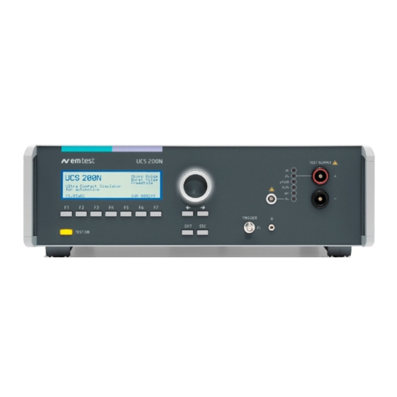
The ultra-compact simulator
UCS 200N - designed as a modular system - is the most
intelligent solution offering exactly what you need for full-
compliant immunity tests against transients. The distinct
operation features, convenient DUT connection facilities, a
clearly arranged menu structure and display philosophy as well
as the free-programmable pulse mode called Freestyle make
testing easy, reliable and safe. Extendable by a variety of test
accessories the UCS 200N is a universal equipment for abroad
range of recommendations even for high current applications up
to 200A
Version: 2.41 / 04.10.2022
Replaces: 2.40 / 12.05.2022
Filename: UserManual-UCS200Nx.2_.3-E-V2.41
Printdate: 04.10.22
•
ISO 7637
•
SAE J1113
•
Manufacturer spec as
per GM, Ford,
Chrysler, Mercedes,
BMW, VW, PSA,
Fiat ......
Advertisement
Table of Contents

Related Manuals for Ametek UCS 200N .2 Series


Summary of Contents for Ametek UCS 200N .2 Series
- Page 1 M a n u a l F o r O p e r a t i o n UCS 200Nx.2 / .3 The ultra-compact simulator • ISO 7637 • SAE J1113 UCS 200N - designed as a modular system - is the most •...
- Page 2 Phone: +41 61 204 41 11 Fax: +41 61 204 41 00 URL : http://www.ametek-cts.com Copyright © 2022 AMETEK CTS GmbH All right reserved. Information in earlier versions. Specifications subject to change. Manual for Operation V 2.41 2 / 54...
-
Page 3: Table Of Contents
General ............................. 39 8.2. Test set-up ............................39 8.3. Calibration and Verification ....................... 40 8.3.1. Factory calibration ..........................40 8.3.2. Guideline to determine the calibration period of AMETEK CTS instrumentation ......40 Manual for Operation V 2.41 3 / 54... - Page 4 AMETEK CTS UCS 200N 8.3.3. Calibration of Accessories made by passive components only ............40 8.3.4. Periodically In-house verification ...................... 40 8.4. Connectors to the DUT ........................41 Delivery .......................... 42 9.1. Basic accessory ..........................42 9.2. Additional Accessories and options (separately available) .............. 43 10.
-
Page 5: Model Overview
AMETEK CTS UCS 200N Model Overview 1.1. Models of the UCS 200N series Each UCS 200Nxxx includes modules for the following pulses: • Pulse 3a/3b up to 1000V peak voltage, wave shape 5/150ns • Pulse 1, 2a as per ISO 7637-2, •... -
Page 6: Standards Covered By Ucs 200Nx Series
AMETEK CTS UCS 200N Standards covered by UCS 200Nx series The UCS 200Nx series covers the following standards - ISO 7637-2:2011 Pulse 1, 2a, 3a, 3b - most manufacturer spec - SAE J1113 Pulse 1. 1a, 1b, 2, 3a, 3b... -
Page 7: Operating Functions
AMETEK CTS UCS 200N Operating Functions 3.1. Front view Display Oscilloscope trigger Function keys "F1...F7" HV pulse output 50 ohm "Test On" 10 Earth plug for verification Knob (Inc / Dec) 11 LED: Indication battery switch 12 LED: Pulses available at + output Cursor keys ""... - Page 8 AMETEK CTS UCS 200N Display Oscilloscope trigger Function keys "F1...F7" HV pulse output 50 ohm "Test On" 10 Earth plug for verification Knob (Inc / Dec) 11 LED: Indication battery switch 12 LED: Pulses available at + output Cursor keys "" and "→"...
-
Page 9: Rear View
AMETEK CTS UCS 200N 3.2. Rear view 11 USB interface 1 DUT test supply input 6 External trigger 12 Parallel interface GPIB / IEEE 488 2 Reference earth connection 7 Warning lamp 13 Remote control connector CN 3 AUX Pulse input from ext. LD... - Page 10 AMETEK CTS UCS 200N 1 DUT test supply input 6 External trigger 11 USB interface 2 Reference earth connection 7 Warning lamp 12 Parallel interface GPIB / IEEE 488 3 AUX Pulse input from ext. LD Safety circuit 13 Remote control connector CN 4 Control input for ext.
-
Page 11: Operation
AMETEK CTS UCS 200N Operation The simulator is operated by an easy menu control system. Seven function keys are available to select parameters and functions. All functions are indicated on the display; max. 8 lines and 40 characters. The selected parameter is blinking and can be changed by turning the knob (incr./decr.). -
Page 12: Main Menu
AMETEK CTS UCS 200N 4.1. Main Menu Other pulses different to ISO 7637 and the standards listed under 9.4 can be generated in Quick Start menu by changing the related parameters or by using the Freestyle programming mode. MAIN MENU... -
Page 13: Service
F3 : Setup F4 : Set default values F1 Addresses The addresses of the AMETEK CTS GmbH and AMETEK CTS Germany GmbH are shown. The addresses of all AMETEK CTS sales agencies are listed on the web site of EM Test under : www.emtest.com... -
Page 14: Tests Pulse1, Pulse 2
AMETEK CTS UCS 200N 4.4. Tests pulse1, pulse 2 The pulse 1 and pulse 2, have the same menu structure. The following sections shows the common menu-items. 4.4.1. Quickstart (pulse 1, pulse 2) The pulses 1, 2, 3a / 3b offers a Quickstart menu. Easy and very fast operation of all standard functions of the equipment. -
Page 15: User Test Routines (Pulse 1, Pulse 2)
AMETEK CTS UCS 200N 4.4.2. User Test Routines (pulse 1, pulse 2) The user can program, save and recall his own specific test routines. The next pages shows the selection of the functions. PULSE 1 USER TEST ROUTINES F1 : Quickstart... -
Page 16: Eft Burst Pulse 3A/3B As Per Iso 7637-2
AMETEK CTS UCS 200N 4.5. EFT Burst pulse 3a/3b as per ISO 7637-2 4.5.1. Operation The Burst menu offers different test routines for burst testing. PULSE 3a/3b USER TEST ROUTINES F1 : Quickstart F1 : Customized test routine F2 : Voltage change after T by V F2 : User test routines F3 : Frequency change after T by f... -
Page 17: User Test Routines
AMETEK CTS UCS 200N 4.5.3. User Test Routines The user can program, save and recall his own specific test routines. The next pages shows the selection of the functions. After selection the last used test parameters will be indicated on the display. -
Page 18: Test Routine As Per Iso 7637
AMETEK CTS UCS 200N 4.5.4. Test Routine as per ISO 7637 The display shows a list of test levels as per the standards ISO 7637. STANDARD TEST ROUTINES : Pulse 3a -150V ISO 7637 / 12V : Pulse 3a -200V... -
Page 19: Test Set-Up
AMETEK CTS UCS 200N 4.6.1. Test Set-up IMPORTANT • The test generator and the coupling network should be connected directly to the reference ground plane. • For the pulses 3a/3b the connection generator – groundplane shall not be longer than 100mm. The connection shall be suitable for high frequencies. -
Page 20: Tests With The Capacitive Coupling Clamp Acc
AMETEK CTS UCS 200N 4.6.3. Tests with the capacitive coupling clamp ACC • The coupling on signal lines is realized with the capacitive coupling clamp. • The coupling clamp has to be terminated with a 50 ohm resistor. • The clamp should be placed in a distance of 0.5m to the equipment under test. When using shorter distances, the DUT may be influenced by radiation. -
Page 21: Freestyle
AMETEK CTS UCS 200N 4.7. Freestyle The Freestyle menu makes it possible to program the rise time and the pulse duration of the generated transients over a broad range. This enables to easy adapt the generators output pulses to new requirements. -
Page 22: Standards
AMETEK CTS UCS 200N 4.8. Standards The Standards menu is based on the following standards: JASO D001 SAE J1455 ISO 7637-1:1990 Pulse 6 Main Menu F1 : JASO F2 : F3 : SAE F4 : ISO 7637-1:1990 Pulse 6 Pulse JASO... -
Page 23: Micro Pulse Generation
AMETEK CTS UCS 200N Micro pulse generation Discharge switch: The discharge switch is a highly reproducible semiconductor switch. 5.1. Pulses as per ISO 7637 Testpulse 1 12V System 24V System 0 .. –600V Vs Voltage 0 .. -100V Ri Impedance 10... -
Page 24: Pulses As Per Sae J 1113
AMETEK CTS UCS 200N 5.2. Pulses as per SAE J 1113 12V System 12V System 24V System Passenger Car and Heavy-Duty Trucks Light-Duty Trucks Testpulse Pulse 1a Pulse 1b Pulse 1c Vs Voltage -25 .. -100V -150 .. -600V -300 .. -600V Ri Impedance 10... -
Page 25: Pulses As Per Jaso D 001
AMETEK CTS UCS 200N 5.3. Pulses as per JASO D 001 Pulse A2 Pulse B2 Pulse D2 Voltage 0...110V 0...-260V 0..170V Capacitor C = 4.7 C = 33F C = 2.2 Pulse duration (36,8%) = 2.5us = 2.0ms ... -
Page 26: Pulses As Per Mbn 10 284 Part 2 : August 2001
AMETEK CTS UCS 200N 5.4. Pulses as per MBN 10 284 part 2 : August 2001 Testpulse 1 12V System 24V System 42V System 42V b System Scenario 1 Scenario 2 Voltage Vs -100V -300V -100V -300V Internal resistor Ri 10... -
Page 27: Special Pulses As Per Vw, Mercedes, Ford, Opel
AMETEK CTS UCS 200N 5.5. Special pulses as per VW, Mercedes, Ford, Opel Pulse 1b as per VW 12V supply 24V supply Test voltage 0 .. -50V 0 .. -50V Internal resistor 10 20 Pulse width td 0.05 ms 0.05 ms Risetime tr 1s... -
Page 28: Ucs 200Nx.3 As Per Vw Tl 820 66 With Pulse 1 And Pulse 2 (4Ω)
AMETEK CTS UCS 200N 5.6. UCS 200Nx.3 as per VW TL 820 66 with Pulse 1 and Pulse 2 (4Ω) The UCS 200Nx.3 models includes the pulse 1 and pulse 2 with a Ri= 4Ω as per Volkswagen standard VW TL... -
Page 29: Test Equipment Ucs 200N
AMETEK CTS UCS 200N Test Equipment UCS 200N Control unit Power supply board Filter board / connecting board Interface board Keyboard / LCD- display Controller board General power supply input, filter Power supply transformer Ventilation High voltage unit High voltage power supply... -
Page 30: Battery Switch
AMETEK CTS UCS 200N 6.1. Battery switch - The battery switch is located on the right part of the equipment and can switch off the battery supply for the DUT. The time off can be selected. The dc power is switched off during pulse generation of e.g. pulse 1. See the figure and the table on the previous page. -
Page 31: The Coupling Network
AMETEK CTS UCS 200N 6.2. The coupling network Via coupling network the pulses are injected to the lines of a vehicle battery supply system, according ISO 7637 as well as SAE J1113. The coupling mode, capacitive coupling to the + line or via capacitive coupling clamp to signal lines, is selected via the front panel keyboard of the UCS 200N or by ISO.control software. -
Page 32: Ucs 200N Coupling Network General Diagram
AMETEK CTS UCS 200N 6.2.1. UCS 200N Coupling network general diagram Input: Pulse Pulse Simulator Type DC power supply +/- and pulse VDS or external Pulse 1, 1a, 2, 6 (ISO) Internal from UCS 200N module Pulse A2, B2 and D2 (Jaso) -
Page 33: Technical Data
AMETEK CTS UCS 200N Technical data 7.1. EFT / Burst pulse 3a/3b as per ISO 7637-2 7.1.1. Pulse specification U = 25V – 1000V Open circuit ± 10 % U = 13V – 500V at 50 ohm ± 10 % Rise time (10%-90%) ±... -
Page 34: Micro Pulses 1 & 2 As Per Iso 7637-2
AMETEK CTS UCS 200N 7.2. Micro pulses 1 & 2 as per ISO 7637-2 7.2.1. Pulse specification and settings No load U = 20V - 200V ±10% Voltage settings 20V - 600V in 5V steps Pulses pulses 1, 1a and 2 as per ISO 7637-2 Source impedance selectable 2, 4, 10, 20, 30, 50,, 90... - Page 35 AMETEK CTS UCS 200N SAE J1113 Pulses SAE pulse 1a Rise time 60s +0% // -50% Pulse width 10%-10% 300s ±10% Source impedance 30 ±10% SAE pulse 1b Rise time 1s +0/ -50% Pulse width 10%-10% 1 ms ±20% Source impedance 20...
- Page 36 AMETEK CTS UCS 200N JASO pulses as per JASO D 001 (only available for UCS 200Nx.2 models) Pulse A2 (12V) JASO Capacitor C = 4.7F Pulse duration (36,8%) = 2.5us ±30% 0.6 ±10% 0.4 ±10% Polarity Positive Pulse B2(12V) JASO Capacitor C = 33F...
-
Page 37: Trigger
AMETEK CTS UCS 200N Examples of manufacturer requirements: MBN 10284 pulses Pulse 1 (12V supply) Rise time 1s +0% // -50% Pulse duration 2 ms ±10% Source impedance 10 ±10% Pulse 1 (24V supply) Rise time 1s +0% // -50% Pulse duration 2 ms ±10%... -
Page 38: Coupling Network
AMETEK CTS UCS 200N 7.3. Coupling Network DC supply voltage max. 80V Options UCS 200N50x UCS 200N100x UCS 200N150x UCS 200N200x DC current 100A 150A 200A Inrush current 500ms 100A 150A Weight 25kg 29.2kg 35.35kg approx. 35kg 19” 3HU 19” 6HU 19”... -
Page 39: Maintenance
AMETEK CTS UCS 200N Maintenance 8.1. General The generator is absolutely maintenance-free by using a solid state semiconductor switch to generate transients. 8.2. Test set-up When setting up the test national and international regulations regarding human safety have to be guaranteed. -
Page 40: Calibration And Verification
AMETEK CTS equipment. AMETEK CTS doesn’t know each customer’s Quality Assurance Policy nor do we know how often the equipment is used and what kind of tests is performed during the life cycle of test equipment. Only the customer knows all the details and therefore the customer needs to specify the calibration interval for his test equipment. -
Page 41: Connectors To The Dut
AMETEK CTS UCS 200N 8.4. Connectors to the DUT For connectors please download the catalogue from Multi Contact : www.multi-contact.com • 100A Plugs and connectors from Multi Contact Note: If the manufacturer says that they’re not available, please explain that it’s part of an existing installation. -
Page 42: Delivery
AMETEK CTS UCS 200N Delivery 9.1. Basic accessory Some of the included basic accessories that are provided with the UCS 200Nx unit depend on the current capability of the unit. All table top UCS 200Nx.2/.3 units come with 1 of the following power mains cables:... -
Page 43: Additional Accessories And Options (Separately Available)
AMETEK CTS UCS 200N 9.2. Additional Accessories and options (separately available) • Remote software " iso.control " - Test, analysis and documentation - Licensed version for testing according most automotive standards - Report generator with export function to word-processing software •... - Page 44 AMETEK CTS UCS 200N • AD-ISO-100A Art # 105267 100A to 32A 4mm banana • MSA 250-32, 1 pair adapter max 32A 4mm banana (# 1004143) 1) to adapt AD-CA ISO 2) for burst verification on the +DUT output line •...
-
Page 45: Appendix
UCS 200N Appendix 10.1. Declaration of CE-Conformity 10.1.1. UCS 200N50 Manufacturer : AMETEK CTS GmbH Address: Sternenhofstr. 15 CH 4153 Reinach Switzerland declares, that under is sole responsibility, the product’s listed below, including all their options, are conformity with the applicable CE directives listed below using the relevant section of the following EC standards and other normative documents. -
Page 46: Ucs 200N100
AMETEK CTS UCS 200N 10.1.2. UCS 200N100 Manufacturer : AMETEK CTS GmbH Address: Sternenhofstr. 15 CH 4153 Reinach Switzerland declares, that under is sole responsibility, the product’s listed below, including all their options, are conformity with the applicable CE directives listed below using the relevant section of the following EC standards and other normative documents. -
Page 47: Ucs 200N150
AMETEK CTS UCS 200N 10.1.3. UCS 200N150 Manufacturer : AMETEK CTS GmbH Address: Sternenhofstr. 15 CH 4153 Reinach Switzerland declares, that under is sole responsibility, the product’s listed below, including all their options, are conformity with the applicable CE directives listed below using the relevant section of the following EC standards and other normative documents. -
Page 48: Ucs 200N200
AMETEK CTS UCS 200N 10.1.4. UCS 200N200 Manufacturer : AMETEK CTS GmbH Address: Sternenhofstr. 15 CH 4153 Reinach Switzerland declares, that under is sole responsibility, the product’s listed below, including all their options, are conformity with the applicable CE directives listed below using the relevant section of the following EC standards and other normative documents. -
Page 49: Ucs 200N - Internal Voltage Drop
AMETEK CTS UCS 200N 10.2. UCS 200N – internal Voltage drop Depends on the pulse setting a different Voltage drop appears inside the UCS 200N. This voltage drop can be compensated by the battery supply (VDS 200) setting, The iso.control software compensate the voltage drop automatically. -
Page 50: Ucs 200N - General Diagram
AMETEK CTS UCS 200N 10.3. UCS 200N - General Diagram Manual for Operation V 2.41 50 / 54... -
Page 51: Main Diagram Control Connection
AMETEK CTS UCS 200N 10.4. Main diagram control connection Manual for Operation V 2.41 51 / 54... -
Page 53: Main Diagram High Voltage Connection
AMETEK CTS UCS 200N Series 10.5. Main diagram high voltage connection Manual for Operation V 2.41 53 / 54... -
Page 54: Setup For Icc Testing As Per Iso 7637-3
AMETEK CTS UCS 200N 10.6. Setup for ICC testing as per ISO 7637-3 For testing as per ISO 7637-3 with the ICC clamp the standard recommends an output voltage of 3V to 10V. These low voltages can not be realized direct with the UCS 200 generator.
Need help?
Do you have a question about the UCS 200N .2 Series and is the answer not in the manual?
Questions and answers
i want to change in test report of CCC pulse 3a and 3b of pulse width duration which is 150nenoseond, so how to change in software setting