
Related Manuals for Ametek LS1 Series


Summary of Contents for Ametek LS1 Series
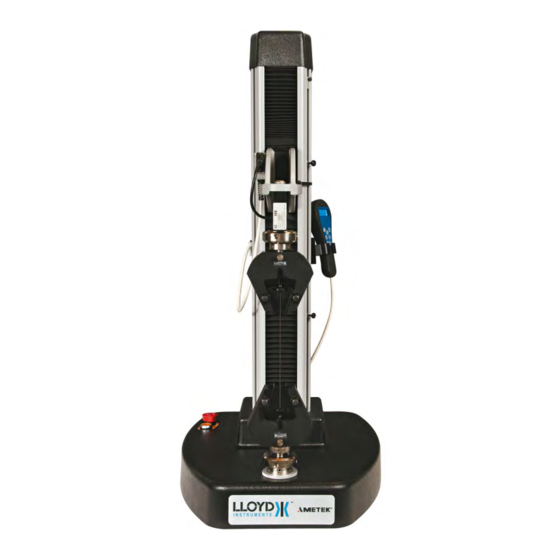
- Page 1 Part No. 01/3682 June 2011 LS1 Series Universal Test Machines User Manual LS User Manual...
- Page 2 This instrument is warranted against defects in workmanship, material and design for one (1) year from date of delivery to the extent that AMETEK will, at its sole option, repair or replace the instrument or any part thereof which is defective, provided, however, that this warranty shall not apply to instru- ments subjected to tampering or, abuse, or exposed to highly corrosive conditions.
- Page 3 ICONS WARNING The raised hand icon warns of a situation or condition that may lead to personal injury or death. Do not proceed until the warning is read and thoroughly understood. Warn- ing messages are shown in bold type. DANGEROUS VOLTAGE The lightning icon warns of the presence of an uninsulated dangerous voltage within the product enclosure that might be of sufficient magnitude to cause serious shocks or death.
- Page 4 Printed below is a copy of an AMETEK Lloyd Instruments declaration that the LS you have meets the requirements for CE marking. Actual copies of the certificate for your type of LS may be obtained from AMETEK, Inc. DECLARATION OF CONFORMITY NAME AND ADDRESS OF MANUFACTURER AMETEK Inc.
-
Page 5: Table Of Contents
TABLE OF CONTENTS INTRODUCTION ....... 6 SETTING UP A NEW TEST ....35 Pre-defined Test Setups ....35 Safety ..........7 Default Global Settings ..... 37 Editing a Pre-defined Test Setup ..37 ELECTRICAL SAFETY ..... 7 Password Access ......37 INSTALLATION ......... -
Page 6: Introduction
1.0 INTRODUCTION For advice and information about the Welcome to your new LS series advanced, NEXYGENPlus™ data analysis and applications single column, universal testing machine. It software, please contact your authorised LLOYD incorporates an extensive range of features INSTRUMENTS Sales Representative. making it ideal for performing complex testing applications. -
Page 7: Safety
These shields have an electronic interlock such that the test cannot be started until the hinged shield is closed. While not mandatory for many applica- tions and countries, AMETEK Lloyd Instruments Ltd. strongly recommends that users consider fitting this option. -
Page 8: Installation
3.0 INSTALLATION 3.1 UNPACKING The LS on its own, without the packing and accessories weighs more than 50kg (110lb). Therefore, safe lifting practices should be employed and lifting equipment used as necessary. The LS test machine is packed in a rugged shipping crate to minimize damage caused from shipping mishandling. -
Page 9: Voltage Selection
3.3 VOLTAGE SELECTION The LS can be used with electricity supplies of either 230Vac ±10% or 115Vac ±10%. The power in- put cable should be inserted at the rear of the machine. Before switching on the machine you MUST check the correct voltage has been selected on the mains input connector. Ensure that the selection is correct for the voltage of your power supply. -
Page 10: On-Off Switch
Extensometer Interface Connector Load Cell Cable Connector USB Port Hand Held Remote or Main Console Connector Emergency Stop Button Safeline Button When illuminated, the safeline switch is open. There is no crosshead movement or motor control. Depress the button to close the switch and allow for motor and crosshead movement. -
Page 11: Additional Load Cells
3.7 ADDITIONAL LOAD CELLS The following standard Load Cells are available for your LS. Description Accuracy Capacity Order Number YLC-0005-A1 0.5% accuracy 01/3871 YLC-0010-A1 0.5% accuracy 01/3872 YLC-0020-A1 0.5% accuracy 01/3873 YLC-0050-A1 0.5% accuracy 01/3874 YLC-0100-A1 0.5% accuracy 100N 01/3875 YLC-0250-A1 0.5% accuracy 250N... - Page 12 NOTE: No specific information about mounting an LS Pogo can be issued with the machine on it’s own because the size and specification of the frame are decided by the customer’s specific needs. The frame should be positioned first and the instructions for set-up and wiring supplied with the frame followed closely.
-
Page 13: Load Cells
4.0 LOAD CELLS 4.1 CARE OF LOAD CELLS ALL machine operators should be aware that LLOYD INSTRUMENTS’ Load Cells are precision force measuring instruments, which should be treated with the utmost care to avoid accidental damage. In particular low force Load Cells are easily damaged if abused or used without sufficient care. NOTE: Do not submit Load Cells to physical shock of any kind. -
Page 14: General Precautions
4.3 GENERAL PRECAUTIONS The following points should be considered: When installing the upper grip (particularly heavy ones) on the load cell eye end, avoid bumping the eye end. If the grip is a close fit, DO NOT FORCE IT, establish the reason and rectify. Im- mediately set, or re-set, the bottom limit stop so the grips will not meet when the crosshead is lowered. -
Page 15: Accessories
5.0 ACCESSORIES 5.1 EXPANDED TABLE An extended base table is available to assist with the testing of wider items. There are 2 versions of the extended table which has 25 tapped holes strategically placed for easy anchoring of the part to be tested using customised jigs and fixtures, additional holes may be added by the user, 1 version has M6 tapped holes the other version has # 10-32 tapped holes LS User Manual... - Page 16 Twenty-five (25) tapped holes for attaching custom fixtures. LS Extended Work Table There are two (2) versions of the table. The part numbers for each are as follows: M6 Threads SPK/LS/0001 #10 – 32 Threads SPK/LS/0002 LS User Manual...
-
Page 17: Drip Tray
5.2 DRIP TRAY The optional Drip Tray (SPK/LS/0003) is designed for catching any liquid that may be spilt when car- rying out a test. The drip tray fits around the bottom anchor pin and is clamped in place by the anchor pin, locking nut or the grip threaded adaptor. -
Page 18: Control Consoles
6.0 CONTROL CONSOLES 6.1 MAIN CONTROL CONSOLE DESCRIPTION The unit has a Liquid Crystal Display (LCD) to show set-up information, load and extension values etc. and a key pad to input information for operating the machine when under control of the console. The machine is set up by answering simple questions and entering information when requested. -
Page 19: Keypad Operation And Description
6.2 KEYPAD OPERATION AND Jog Keys DESCRIPTION Fast Jog Zero The keypad has 25 keys arranged into 4 groups. The first group contains 8 keys in the bottom right hand corner of the keypad The First Group of Keys The GO button is used to start a test from the machine console and is operable from the “Pre-Test”... - Page 20 The second group contains 4 keys directly below the display. These “Soft Keys” are used to select various options that are identified by the text displayed on the lower lines of the display as described later. Dynamic Function Keys Mapped to Displayed Information ALPHA-NUMERIC KEYS contains 12 keys on the left hand side of the keypad.
-
Page 21: The Display
6.3 THE DISPLAY The display, which has 4 lines of 40 characters, is used to show or request information. The informa- tion displayed depends upon the status of the machine but generally, the top line displays a title or help information for each display. The lower lines are split into 4 blocks, one block above each Soft Key, to indicate the function of that key. -
Page 22: Handheld Remote Control
Select the required test New Test < Create To define a test, refer to Section 9.0 SETTING UP A NEW TEST, noting that the supervisor may add a password to prevent the operator from entering the EDIT or CREATE modes. 6.5 HANDHELD REMOTE CONTROL The handheld remote control is used when NEXYGEN™... -
Page 23: Displayed Units On The Handheld Remote Control
6.6 DISPLAYED UNITS ON HANDHELD REMOTE CONTROL The handheld remote control can display the load and extension values in 1 of 3 combinations: N and mm kgf and mm lbf and in To change the displayed units, press ZERO key 2 times when “Lloyd Instruments” is displayed im- medialtely after the machine is switched on The displayed units will change in sequence: If N and mm is displayed, these will change to show kgf and mm... -
Page 24: Operational Precaution
All operators must receive adequate training in basic operation before being allowed to use the machine. Additional copies of this manual are available from AMETEK Inc. Operators must ensure that the Emergency Stop Button is never obstructed. -
Page 25: Emergency Stop
7.2 EMERGENCY STOP If for any reason, the machine needs to be stopped without delay, an emergency stop mushroom switch is provided. Pressing the switch stops the LS machine immediately. It can be released by turning a quarter-a-turn clockwise. The machine will then go to the initialized/start-up sequence if the ON/OFF switch is already ON. -
Page 26: Lower Anchor Pin Adjustment
7.4 LOWER ANCHOR PIN ADJUSTMENT The Lower Anchor Pin can be adjusted to align itself with the attached load cell. To align the load cell to the lower anchor pin lower the load cell on to the moving ram so that it is very close to the lower anchor pin using the jog keys. -
Page 27: Limit Stops
LIMIT STOPS The LS machines are fitted with two mechanically activated limit stops. These can be used as extra protection to stop load cells, grips or fixtures coming into contact. The upper one can be used to back up the software limit. Activating a limit stop will result in the machine stopping. To adjust the lower limit stop, first loosen the lower limit stop screw and move the stop to the bot- tom of its travel in the slot. - Page 28 If during a test or when manoeuvring the crosshead, a limit stop switch is activated, a display as shown below or similar will be seen. ERROR condition Lower limit switch press ENTER to cancel When ENTER has been pressed and this display has been cleared the machine will only allow the operator to drive the crosshead away from the limit stop.
-
Page 29: Performing A Test
8.0 PERFORMING A TEST 8.1 PERFORMING A TEST The LS machines can be used to perform tests in two modes, as a stand-alone machine or under computer control with NEXYGENPlus™ software. If the machine is to be used with a computer and NEXYGENPlus™ software, then the NEXYGEN- Plus™... -
Page 30: Selecting A Test
8.3 SELECTING A TEST The user selects the required existing pre-programmed test by pressing the left and right arrow Soft Keys until the required test is shown on the display, then pressing the Test Soft Key. Select the required test CYCLE_TEST (150 samples) Test <... - Page 31 If the batch questions option is turned on, then the following screen will be displayed. A “batch” being a series of tests all carried out with the same settings. The “batch questions” are 3 two word ques- tions which can be set-up at the beginning of a new “batch” Press a key to change a parameter OPERATOR BATCH...
- Page 32 The extension symbols or indicate the direction of the extension from the “soft zero” position. “Soft zero” being the position at which the ZERO key was last pressed. The load symbols or indicate a Tensile Force or Compressive Force, respectively. If the sample questions option is turned on, then next to the test name the sample width and thick- ness, diameter or area information will be shown.
-
Page 33: Starting A Test
8.4 STARTING A TEST When all the test parameters have been set as per 8.3 SELECTING A TEST above, press GO to start the test and display one of the screens below. For a Limit Test: Performing Test MOULDED_RUBBER Moving to limit point 10.00mm Load 276N... -
Page 34: Viewing The Statistics
8.8 VIEWING THE STATISTICS Pressing the Stats Soft Key will accept the result and show the statistics screen as below:- Pk Load Pk Ext Mean 367N 126.57m Dev’n 24.18mm Print > Pressing > Soft Key will show the second statistics screen:- Brk Load Brk Ext Mean 137N... -
Page 35: Setting Up A New Test
SETTING UP A NEW TEST PRE-DEFINED TEST SETUPS The LS is supplied with three pre-defined test setups and one for new test setups, these are: LIMIT_TEST A test which is carried out to a limit. The limits are defined in mm or inches, % elongation (after setting gauge length), Newtons, Kg force, lbs force, Mega Pascal’s Mpa (have entered the sample dimensions), Kg force per mm²... - Page 36 The Default test setups are as follows: Test name > LIMIT_TEST CYCLE_TEST BREAK_TEST NEW_TEST Test Type Settings Test mode Tension Tension Tension Tension Test type Limit Cycling Limit Limit Limit position 10.0mm 10.0mm 10.0mm Home position 0.0mm No. of cycles Preload 0.0N 0.0N...
-
Page 37: Default Global Settings
9.2 DEFAULT GLOBAL SETTINGS The Default Global Settings are: Field Setting Password <None> Safety load Slow jog speed 25mm/min Data format Printer Grip protection Tension 110% of frame rating Grip protection Compression 110% of frame rating Language English To enter a New Test Setup or Edit a pre-defined setup, proceed as follows. 9.3 EDITING A PRE-DEFINED TEST SETUP To edit a previously defined test setup, select the required test, using the left and right arrow keys, until the required test is displayed then press the Edit Soft Key. -
Page 38: Renaming The Test
9.5 RENAMING A TEST Pressing the Rename Soft Key will allow the setup name to be changed. If a new test is created, the name will be automatically set to new_test. 9.6 DELETING A TEST Pressing the Delete Soft Key will allow the selected test setup and all associated sample results to be deleted. -
Page 39: Setting A Password
SETTING A PASSWORD Pressing the Change Password Soft Key brings up the following display: Change or create the password CHRIS BkSp Clear All Pressing BkSp Soft Key deletes one character at a time starting from the right hand end of the password. -
Page 40: Machine Stiffness
9.14 MACHINE STIFFNESS Pressing the SET MACHINE STIFFNESS soft key allows the user to perform a machine stiffness compensation. Select Machine Stiffness compensation Empty 1 Rename < > Setup Use the < or > soft keys to select the machine stiffness compensation slot to use for the compensa- tion. -
Page 41: Test Type
9.16 TEST TYPE Pressing the Test Type Soft Key will allow the test type to be defined. Press a key to change a parameter Test Test Mode Type Limit Tension Limit Values > Pressing the > Soft Key will toggle between the display above and the next display. Press a key to change a parameter Speed Machine... - Page 42 Pressing the Set Cycling Values Soft Key will allow the values to be set. Press a key to change a parameter Limit Home Number 20.0 10.0 of Cycles The Home position is the start of the Cycle Test position and wherever the machine is resting after loading it will drive first to the Home position.
-
Page 43: Selecting Machine Stiffness Compensation
9.17 SELECTING MACHINE STIFFNESS COMPENSATION Press a key to change a parameter Speed Machine Preload Stiffness mm/min Values Disabled < Pressing the Machine Stiffness soft key enables the user to select the machine stiffness compensation to use in the current selected test setup Press a key to change a parameter Empty 1 Enabled... - Page 44 Press a key to change a parameter Plotter Output disabled > By pressing the Break Detector Soft Key the following display is shown Sharp Break Detector Press a key to change a parameter Sharp Percent Start Break Break There are two break detectors, a sharp break detector and a percentage of peak load break detector. The sharp break detector operates when there has been a sharp change in load or direction between one load reading and the next.
- Page 45 Pressing the Extenso’r Used Soft Key will allow the selection of any extensometer currently fitted from the following screen. Select an extensometer LS Materials Testing Machine < > The left and right arrow ( < > ) Soft Keys will scroll through the list of currently connected extensom- eters, (theoretically a maximum of 4 with the internal crosshead position always being listed as one of these).
-
Page 46: Test Results
9.19 TEST RESULTS Pressing the Test Results Soft Key from the Test Setup Display will allow the test results units and pass/fail limits to be set. Press a key to change a parameter Test Pass/Fail Results Checks Units Pressing the Tests Result Units Soft Key allows the units to be set. Press a key to change a parameter Peak Peak... -
Page 47: Defining Sample
9.21 DEFINING SAMPLE Pressing the Define Sample Soft Key from the Test Setup Display will allow the sample/batch details to be set. Press a key to change a parameter Batch Sample Sample Pre-test Questions Question Info Questions The Batch Questions and Sample Question Soft Keys toggle between On and Off to specify which pre-test question displays will be shown. -
Page 48: Error Condition
10.0 ERROR CONDITIONS 10.1 ERROR CONDITIONS On the LS, if an error occurs, a message will be displayed on the console describing the error. This mes- sage must be cleared by pressing the ENTER key before proceeding. Some errors are displayed when the machine is first powered on and indicate faults that were detected during the power up sequence. - Page 49 Unexpected reset code XX Unexpected software reset code XXX Software reset code 106 (XXXXXX) These messages indicate that an internal error has caused the system to reset unexpectedly. Please make a note of the readings and contact LLOYD INSTRUMENTS Technical Support for help. System Hardware Error An error has occurred in the internal electronics of the system.
-
Page 50: Cleaning And Maintenance
Unexpected reset code 40 Unexpected reset code 80 Unexpected software reset code 100 Unexpected software reset code 101 Unexpected software reset code 102 Unexpected software reset code 103 Unexpected software reset code 104 Unexpected software reset code 105 Software reset code 106 (000000) Loadcell calibration due System Hardware Error Drive System Error... -
Page 51: Technical Specification
12.0 TECHNICAL SPECIFICATION 12.1 TECHNICAL SPECIFICATION LS1 STANDARD TRAVEL Maximum Force (Tension and Compression) 1000N (225lbf) Crosshead Travel Between Eye Ends 500mm (19.7in) Throat Depth 180mm (7.1in) Displayed Distance Resolution 0.01mm (.001in) Crosshead Speed Range 0.01 to 2032mm/min (0.001-80in/min) Crosshead Speed Accuracy - Unloaded +/-0.2% of Selected Speed - 2% to 100% of Max Speed Crosshead Distance Accuracy - Unloaded +/-0.2% of Reading - 2% to 100% of Max Travel... -
Page 52: Overall Dimensions Ls
12.3 OVERALL DIMENSIONS LS Height (standard travel) 1016 40.0 Height (extended travel) 1301 51.2 Width (excluding console) 18.1 Depth 21.9 Base Height Throat Depth LS User Manual... -
Page 53: Rohs Tables
13.0 RoHS TABLES Restricted Substance Status Table Page 1 Restricted Substance Status Table Page 2 LS User Manual... -
Page 54: Spare Parts Kits
14.0 SPARE PARTS KITS LS User Manual... - Page 55 TO 18 TO 1 TO 2 TO 1 TO 2 TO 2 TO 2 TO 13 TO 12 TO 2 TO 1 TO 2 LS User Manual...
- Page 56 The material in this document is for information purposes only and is subject to change without notice. While reasonable efforts have been made in the preparation of this Part No. 01/3682 document to assure its accuracy, AMETEK, Inc. assumes no liability resulting from errors or omissions in this document, nor from the use of the information contained herein. June 2011 ©...
Need help?
Do you have a question about the LS1 Series and is the answer not in the manual?
Questions and answers