Table of Contents
Advertisement
Quick Links
INVERTER
Plug-in option
FR-A8NS
INSTRUCTION MANUAL
SSCNET III(/H)
communication function
PRE-OPERATION INSTRUCTIONS
INSTALLATION
WIRING
SSCNET III(/H) COMMUNICATION
STATUS
INVERTER SETTING
RESTRICTIONS ON THE FUNCTIONS
Instructions for SSCNET III(/H)
communication
PROTECTIVE FUNCTIONS
TROUBLESHOOTING
1
2
3
4
5
6
7
8
9
Advertisement
Table of Contents

Related Manuals for Mitsubishi Electric FR-A8NS


Summary of Contents for Mitsubishi Electric FR-A8NS
- Page 1 INVERTER PRE-OPERATION INSTRUCTIONS Plug-in option INSTALLATION FR-A8NS WIRING INSTRUCTION MANUAL SSCNET III(/H) COMMUNICATION STATUS SSCNET III(/H) INVERTER SETTING communication function RESTRICTIONS ON THE FUNCTIONS Instructions for SSCNET III(/H) communication PROTECTIVE FUNCTIONS TROUBLESHOOTING...
-
Page 2: Safety Instructions
Safety instructions Thank you for choosing this Mitsubishi Electric inverter plug-in option. This Instruction Manual provides handling information and precautions for use of this product. Incorrect handling might cause an unexpected fault. Before using this product, read all relevant instruction manuals carefully to ensure proper use. - Page 3 Injury prevention CAUTION The voltage applied to each terminal must be as specified in the Instruction Manual. Otherwise an explosion or damage may occur. The cables must be connected to the correct terminals. Otherwise an explosion or damage may occur. ...
- Page 4 CAUTION Usage As all parameters return to their initial values after Parameter clear or All parameter clear is performed, the needed parameters for operation of the inverter and this product must be set again before the operation is started. ...
-
Page 5: Table Of Contents
Wiring example (when FR-A8AP is used)........................30 SSCNET III cable ................................33 3.3.1 Mitsubishi Electric SSCNET III cable ..........................33 3.3.2 SSCNET III cables manufactured by Mitsubishi Electric System & Service Co., Ltd............36 3.3.3 Instructions for laying the SSCNET III cable ........................37 Wiring....................................39... - Page 6 Control method selection ..............................57 RESTRICTIONS ON THE FUNCTIONS Function restriction list..............................61 Inverter parameter list ..............................64 6.2.1 Invalid parameters when the FR-A8NS is used ........................64 6.2.2 Invalid parameters when the FR-A8NS is used and "0 or 1" is set in Pr.499..............74...
- Page 7 Restricted Use of Hazardous Substances in Electronic and Electrical Products ........85 Appendix 4 Referenced Standard (Requirement of Chinese standardized law) ............86 Appendix 5 Compliance with the UK certification scheme .....................87 Appendix 6 List of error codes displayed on the Mitsubishi Electric motion controllers ..........88 REVISIONS...
-
Page 8: Pre-Operation Instructions
PRE-OPERATION INSTRUCTIONS Unpacking and checking the product Take the plug-in option out of the package, check the product name, and confirm that the product is as you ordered and intact. This product is a plug-in option made for the FR-A800 series inverters. 1.1.1 Product confirmation Check the enclosed items. -
Page 9: Serial Number Check
1.1.2 SERIAL number check The FR-A8NS can be used with the models of inverters listed below which have the following SERIAL number. Check the SERIAL number indicated on the inverter rating plate or package. Rating plate example □ ○ ○ ○○○○○○... - Page 10 • SSCNET III communication supported Model Country of origin indication SERIAL number FR-A820-00046(0.4K) to 04750(90K) 58 or later MADE in Japan FR-A840-00023(0.4K) to 06830(280K) FR-A842-07700(315K) to 12120(500K) 59 or later MADE in China FR-A846-00023(0.4K) to 03610(132K) •...
- Page 11 • As shown in the following table, the availability of communication methods and function depends on a SERIAL number combination of the applied inverter and FR-A8NS. Check the circuit board of the FR-A8NS for its SERIAL number. • Availability of communication methods...
- Page 12 • Availability of the settings "100" and "101" of Pr.499 For the inverter manufactured in Japan SERIAL number of the FR-A800 series inverter SERIAL number of the 6Z to FR-A8NS 6Y or earlier 75 or later 74 6X or earlier Invalid (E.OPT occurs.)
- Page 13 • SERIAL number example of the FR-A8NS ○○○ Symbol Year Month Control number The SERIAL consists of one symbol, two characters indicating the production year and month, and three characters indicating the control number. The last digit of the production year is indicated as the Year, and the Month is indicated by 1 to 9, X (October), Y (November), or Z (December).
-
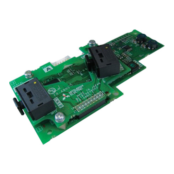
Page 14: Component Names
Component names Front view Rear view Refer to Symbol Name Description page Used to fix this product to the inverter by inserting a mounting screw or a Mounting hole spacer. Used to connect the servo system controller, or the preceding axis inverter/ SSCNET III cable connector (CN1A) servo amplifier. - Page 15 Refer to Symbol Name Description page Switch for manufacturer setting (SW2, Do not change the switch setting from the initial setting (1: OFF). — SW3) PRE-OPERATION INSTRUCTIONS...
-
Page 16: Related Manuals
Related manuals For the details of the servo system controller, refer to the manual or the software Help of each model. Refer to the following manuals for information on the MELSEC iQ-R series motion controller. Manual name Manual number MELSEC iQ-R Motion Controller User's Manual IB-0300235 MELSEC iQ-R Motion Controller Programming Manual (Common) IB-0300237... -
Page 17: Operation Overview
Operation overview In communication with the Mitsubishi Electric servo system controller, the inverter operation or monitoring is enabled with a program in the servo system controller. Application of optical communication method enabled high speed communication of SSCNET III(/H). • Example of Vector control (When the FR-A8AP/FR-A8AL is installed and "0 or 1" is set in Pr.499) - Page 18 • Example of Vector control (When a feedback device interface option is installed and "100 or 101" is set in Pr.499) Servo system controller FR-A800 Motion control FR-A8NS Emergency stop Torque command output shutoff SSCNET SSCNET Position command Speed command ΙΙΙ...
- Page 19 • Example of PM sensorless vector control (When the MM-CF motor is used, no feedback device interface option is installed, and "100 or 101" is set in Pr.499) Servo system controller FR-A800 FR-A8NS Motion control Emergency stop Torque command output shutoff...
-
Page 20: Communication Specifications Of Sscnet Iii And Sscnet Iii/H
Up to 8 axes controlled in a system. 0.444 ms Set the axis number between 0 to 7 using the axis number switch on the FR-A8NS. An inverter set as the axis number between 8 to F cannot be recognized. -
Page 21: Installation
INSTALLATION Pre-installation instructions Check that the inverter's input power and the control circuit power are both OFF. CAUTION • Do not install or remove this product while the inverter power is ON. Doing so may damage the inverter or this product. •... -
Page 22: Installation Procedure
Installation procedure Installation of the FR-A8NS Fit the board mounted option connector on this product to the guide of the option connector on the inverter, and insert the option as far as it goes. (Attach this product to option connector 1 on the inverter.) Fasten this product to the inverter using the two mounting screws through the holes on either side (tightening torque: 0.33... - Page 23 Insertion positions for screws Connector 3 Mounting screw Connector 2 Connector 1 Do not plug this product into connector 2. Mounting screw INSTALLATION...
- Page 24 Install an appropriate feedback device interface option according to a desired control method and feedback device. Control method Feedback device Option FR-A800 FR-A800-E Position control FR-A8AL Case 1 Available Case 1 Encoder FR-A8AP Case 1 Case 4 Available FR-A8TP Case 2 Case 2 Available Vector control...
- Page 25 Connect the enclosed CON2 connector cable (refer to page 7) between the CON2 connector on the FR-A8NS and the CON2 connector on the FR-A8AP/FR-A8AL. (For replacement from the former model FR-A7NS, do not use the FR- A7AP/FR-A7NS connection cable used for the FR-A7NS because it is not compatible.)
- Page 26 Attach the FR-A8APR/FR-A8APS/FR-A8APA to option connector 2 or 3 on the inverter. For details of the installation, refer to the Instruction Manual of each plug-in option. The enclosed CON2 connector cable is not required. Connector 3 Occupied by Use connector 2 or 3 for the FR-A8NS. the FR-A8APR/FR-A8APS/FR-A8APA. Connector 2 Connector 1 INSTALLATION...
- Page 27 Attach the FR-A8AP into option connector 3 on the inverter. For details of the installation, refer to the Instruction Manual of the FR-A8AP. Set "100 or 101" in Pr.499 SSCNET III(/H) operation selection. The enclosed CON2 connector cable is not required. Use connector 3 for the FR-A8AP. Connector 3 Occupied by the FR-A8NS. Connector 1 Ethernet connector INSTALLATION...
- Page 28 Option connector 2 Option connector 3 • When removing the FR-A8NS, remove the two screws on either side, then pull it straight out. Pressure applied to the connector and to the option board may break the option. • To perform SSCNET III(/H) communication using the FR-A800-E inverter with the FR-A8AL installed, remove the pre- installed Ethernet board from the inverter.
-
Page 29: Axis Number Setting
Set the axis number between 0 to F using the axis number switch (refer to page 13) on the FR-A8NS. The setting is applied at the next power-on or inverter reset. Set the switch marked with an arrow ( ) to the axis number (0-9, A-F) corresponding to the desired axis. -
Page 30: Wiring
NOTE • Up to 16 inverters (with the FR-A8NS each) can be used for axis number setting in a system. • When using MT Developer2, refer to the following table to select the appropriate amplifier model according to your system setting on the amplifier setting screen. -
Page 31: Wiring Example (When Fr-A8Ap Is Used)
AC power supply T/L3 Earth External (Ground) Thermal relay thermal protector 2W1kΩ relay input SSCNET III(/H) unit FR-A8AP FR-A8NS CON2 connector CON2 connector cable Encoder SSCNET III Differential Servo system controller, or preceding axis inverter cable connector /servo amplifier (CN1A) - Page 32 The pin number differs according to the encoder used. Speed control and torque control are properly performed even without connecting Z phase. Connect the encoder to the motor shaft so that there is no looseness. Speed ratio should be 1:1. Earth (Ground) the shielded cable of the encoder cable to the enclosure with a P clip, etc.
- Page 33 NOTE • For the details of the input terminals of the inverter, refer to the Instruction Manual (Detailed) of the FR-A800 inverter. • For the details of the FR-A8AP, refer to the Instruction Manual of the FR-A8AP. • On the FR-A8AL, connect encoder cables to terminals PA, PAR, PB, PBR, PZ, PZR, PG, and SD. For the details, refer to the Instruction Manual of the FR-A8AL.
-
Page 34: Sscnet Iii Cable
Electric System & Service Co., Ltd. for long distance cables of up to 100 m and ultra-long flex life cables. (Refer to page 36.) 3.3.1 Mitsubishi Electric SSCNET III cable Cable model name Distance between Type Cable length (m) - Page 35 Specifications Item MR-J3BUS[]M MR-J3BUS[]M-A MR-J3BUS[]M-B Cable length (m) 0.15 0.3 to 3 5 to 20 30 to 50 Minimum bend Enforced covering cord: 50 Enforced covering cord: 50 Cord: 25 Cord: 30 radius (mm) Tension 420 N 980 N 70 N 140 N strength...
- Page 36 Outline drawings • MR-J3BUS015M (6.7) (15) (13.4) (37.65) Protective tube (Unit: mm) • MR-J3BUS03M to MR-J3BUS3M Protective tube ∗1 ∗1 (100) (100) (Unit: mm) Model MR-J3BUS03M MR-J3BUS05M MR-J3BUS1M MR-J3BUS3M L (m) Dimension of connector part is the same as that of MR-J3BUS015M. WIRING...
-
Page 37: Sscnet Iii Cables Manufactured By Mitsubishi Electric System & Service Co., Ltd
1 to 100 Ultra-long bending life Long distance cable Brackets [ ] in a model name indicate the cable length (1 to 100). NOTE • For the details of the SC-J3BUS[]M-C, contact Mitsubishi Electric System & Service Co., Ltd. WIRING... -
Page 38: Instructions For Laying The Sscnet Iii Cable
3.3.3 Instructions for laying the SSCNET III cable SSCNET III cable is made of optical fiber. Application of a power such as a major shock, abrupt bending, haul, lateral pressure, or torsion to the fiber-optic cable will deform or break the inside, disabling optical transmission. Read described item of this subsection carefully and handle it with caution. - Page 39 Lateral pressure Applying a lateral pressure to the fiber cable deforms the cable itself and applies pressure to the internal fiber, resulting in increase in transmission loss. If a larger pressure is further applied, the cable may be disconnected. As the same condition also occurs at cable laying, do not tighten up optical cable with a thing such as nylon band (TY-RAP).
-
Page 40: Wiring
Wiring Remove the inverter front cover and the connector cap of the SSCNET III cable connector (CN1A, CN1B) on the FR-A8NS to insert the SSCNET III cable to the connectors. Refer to page 33 for types of the SSCNET III cable. -
Page 41: Sscnet Iii(/H) Communication Status
SSCNET III(/H) COMMUNICATION STATUS When the inverter is powered ON while Pr.499 SSCNET III(/H) operation selection is set to a value other than "9999" and the X85 signal is turned OFF, the inverter is ready to start the SSCNET III(/H) initial data communication (initialized communication). -
Page 42: State Transition Diagram Of The Inverter
State transition diagram of the inverter The number in a box in the diagram below is the indicated monitor data of the SSCNET III(/H) communication status. (Refer to page 43.) The inverter is powered ON. The inverter is reset after Pr.499 "9999". - Page 43 The inverter is set in the SSCNET III(/H) operation mode and cannot be switched in the External operation or PU operation mode. In addition the operation mode setting in Pr.79 Operation mode selection is invalid. Refer to page 53 for the reset method of the inverter protective function. If the inverter protective function is reset by the inverter power reset, the inverter recovers in the communication waiting status after powering on again.
-
Page 44: List Of Sscnet Iii(/H) Communication Status
• When the setting of the axis number switch in the servo system controller does not match the actual setting of the axis number on the FR-A8NS and the indication of the SSCNET ΙΙΙ(/H) communication status is as follows: "120""121"... - Page 45 SSCNET III(/H) Inverter communication Description operation status Fault A fault (inverter protective function for faults) During initialization, the warning indication "CF" may be displayed on the PU. On the operation panel, the warning indication "CF" and the communication status is displayed alternately when the warning CF is activated. (For how to monitor the SSCNET III(/H) communication status, refer to page 40.)
-
Page 46: Inverter Setting
INVERTER SETTING Parameter list The following parameters are used for the FR-A8NS. Set the values according to need. For the parameter details, which depend on the applicable model of the inverter, refer to the Instruction Manual (Detailed) of the inverter. - Page 47 A917 Analog source selection (8ch) Available when the FR-A8NS is installed. The setting is applied after the CPU reset of the servo system controller or at the next inverter power-ON. When the Pr.499 setting is switched between "9999" and any of other than "9999", the setting is applied after an inverter reset or power- When the Pr.800 setting is changed while "0 or 1"...
-
Page 48: Operation At Communication Error Occurrence
Operation at communication error occurrence 5.2.1 Fault and measures Inverter operation in each operation mode at error occurrences Operation mode Location Status SSCNET III(/H) External operation PU operation operation Inverter operation Output shutoff Output shutoff Output shutoff Inverter Data communication Continued Continued Continued... -
Page 49: Inverter Reset
Inverter reset The following methods are available for the inverter reset during SSCNET III(/H) communication (SSCNET III(/H) operation mode). • Servo system controller error reset at fault occurrence in the inverter (reset can be made only when the protective function of the inverter is activated.) •... -
Page 50: Setting Sscnet Iii(/H) Communication Function
Setting SSCNET III(/H) communication function 5.4.1 Pr.499 SSCNET III(/H) operation selection Use Pr.499 SSCNET III(/H) operation selection to set the SSCNET III(/H) communication availability or the inverter operation at communication disconnection. The Pr.499 setting is applied after an inverter reset. Inverter Inverter reset operation at... - Page 51 NOTE • If an error such as a CRC check error, etc. occurs in the communication data, the communication option fault E.OP1 occurs regardless of the Pr.499 or X85 setting. • Refer to page 53 for the reset method of the inverter protective function. •...
- Page 52 Operation mode switchover method when the SSCNET III(/H) communication is enabled (Pr.79 = "0") Power-ON ∗1 External operation PU operation The inverter starts up in the External operation mode when the X85 signal is turned ON. Symbol Operation mode switching Switchover method External operation →...
- Page 53 NOTE • In the SSCNET III(/H) operation mode, the following settings are disabled: Pr.79 Operation mode selection, Pr.338 Communication operation command source, Pr.339 Communication speed command source, Pr.340 Communication startup mode selection, and Pr.550 NET mode operation command source selection. •...
- Page 54 Reset method of the inverter faults • When Pr.499 = "0 or 100" In the SSCNET III(/H) operation mode, the following faults can be reset by the inverter reset only by power supply reset, turning ON the RES signal, or pressing on the PU.
-
Page 55: Sscnet Iii(/H) Communication Disabled Signal
• When Pr.499 = "1 or 101" The inverter reset by the servo system controller error reset is also enabled to reset any inverter fault. (The fault cannot be reset by the servo system controller CPU reset.) 5.4.2 SSCNET III(/H) communication disabled signal •... -
Page 56: Pr.379 Sscnet Iii(/H) Rotation Direction Selection
5.4.3 Pr.379 SSCNET III(/H) rotation direction selection The rotation direction of the motor can be changed using Pr.379. (Setting of Pr.379 is required regardless of the control method.) To operate the inverter under Vector control when "0 or 1" is set in Pr.499 SSCNET III(/H) operation selection, always match the setting of Pr.359 Encoder rotation direction (0, 100/1, 101) and rotation direction (CW/CCW) of the encoder as viewed from the load side of the motor before setting Pr.379 SSCNET III(/H) rotation direction selection. -
Page 57: Pr.449 Sscnet Iii(/H) Input Filter Setting
5.4.4 Pr.449 SSCNET III(/H) input filter setting Use Pr.449 SSCNET III(/H) input filter setting to select a filter setting for the following input signals. Input signal Parameter setting LSP (Upper stroke limit) signal Pr.178 to Pr.189 (Input terminal function selection) = "88" STF (Upper stroke limit) signal Pr.178 STF terminal function selection = "60"... -
Page 58: Input Terminal Function Selection
"23" in Pr.178 to Pr.189 (Input terminal function selection). 5.4.6 Control method selection Pr.800 Control method selection Specifications of Pr.800 Control method selection when the FR-A8NS is installed are as follows depending on the setting of Pr.499 SSCNET III(/H) operation selection. Operation Pr.499 setting... - Page 59 Availability of control mode when the FR-A8NS is used Pr.499 = "0 or 1" Pr.499 = "100 or 101" Control mode Control method Speed Torque Position Speed Torque Position control control control control control control ...
- Page 60 The number of pulses per motor rotation The number of pulses output by a feedback device per motor rotation depends on the control method and the feedback control option as follows. Control method Feedback control option Number of pulses Pr.862 = "0"...
- Page 61 Data and device for position control The following shows the availability and difference of data by the type of devices for position control. Data by device type Position Description of information IPM motor information Encoder Resolver Endat SinCos (MM-CF) Accumulated value of feedback Estimates by Position feedback...
-
Page 62: Restrictions On The Functions
RESTRICTIONS ON THE FUNCTIONS Function restriction list Invalid inverter functions during SSCNET III(/H) communication operation are as follows. While the following functions are invalid, signal input/output and monitoring related to the functions are disabled. For the details of the related I/O signals and monitors, refer to the Instruction Manual (Detailed) of the inverter. Item Function •... - Page 63 Item Function E: Environment setting parameters • IPM parameter initialization • Acceleration/deceleration time, acceleration/deceleration pattern selection Remote setting F: Parameters for settings of acceleration/ • Starting frequency during speed control or position control, and start-time hold function deceleration time and acceleration/ •...
- Page 64 Item Function N: Parameters for communication operation • Stop mode selection at communication error (Pr.502) and its settings • Operation frequency during communication error (Pr.779) • Magnetic flux command Parameters for vector control • Torque command reverse selection (Pr.1114) • Fast-response operation under vector control (when Pr.800 = "100 or higher") Plug-in options •...
-
Page 65: Inverter Parameter List
Inverter parameter list Name Reference value at acceleration The setting of the following parameters is invalid when the Reference value at deceleration FR-A8NS is installed. Starting frequency for elevator mode 6.2.1 Invalid parameters when the FR- Retry selection A8NS is used... - Page 66 Name Name MC switchover interlock time Override bias Start waiting time Override gain Bypass selection at a fault Main circuit power OFF waiting time Automatic switchover frequency from inverter to bypass Power failure stop selection operation Subtracted frequency at deceleration start Acceleration/deceleration time switching frequency Subtraction starting frequency Stall prevention level at 0 V input...
- Page 67 Name Name Automatic acceleration/deceleration Internal stop position command Acceleration/deceleration separate selection Orientation in-position zone UV avoidance voltage gain Servo torque selection Frequency search gain 16-bit data selection Rotation direction detection selection at restarting Position shift BCD input bias Orientation position loop gain BCD input gain Completion signal output delay time BIN input bias...
- Page 68 Name Name Inverter operation lock mode setting Digital position control sudden stop deceleration time Position command source selection First target position lower 4 digits Command pulse scaling factor numerator (electronic gear First target position upper 4 digits numerator) Second target position lower 4 digits Command pulse multiplication denominator (electronic gear Second target position upper 4 digits denominator)
- Page 69 Name Name Fourteenth target position upper 4 digits Output interruption detection level Fifteenth target position lower 4 digits Output interruption cancel level Fifteenth target position upper 4 digits Traverse function selection PLC function flash memory clear Maximum amplitude amount Communication error execution waiting time Amplitude compensation amount during deceleration Communication error occurrence count display Amplitude compensation amount during acceleration...
- Page 70 Name Name Second brake opening current selection Second PID proportional band Second brake operation frequency selection Second PID integral time Power failure stop frequency gain Second PID differential time Second droop gain PID unit selection Second droop filter time constant Pre-charge fault selection Second droop function activation selection Pre-charge ending level...
- Page 71 Name Name Speed setting filter 2 Terminal 4 frequency setting bias (904) Speed detection filter 2 Torque setting filter 2 Terminal 4 frequency setting gain frequency (905) Torque detection filter 2 Terminal 4 frequency setting gain Torque bias selection (905) Torque bias 1 Terminal 1 bias frequency (speed) Torque bias 2...
- Page 72 Name Name 1015 Integral stop selection at limited frequency Terminal 6 bias (torque) (928) 1072 DC brake judgment time for anti-sway control operation 1073 Anti-sway control operation selection Terminal 6 gain command (torque) (929) 1074 Anti-sway control frequency Terminal 6 gain (torque) 1075 Anti-sway control depth (929)
- Page 73 Name Name 1148 Second output interruption detection level 1243 Sixth positioning deceleration time 1149 Second output interruption cancel level 1244 Sixth positioning dwell time 1150 1245 Sixth positioning sub-function User parameters 1 to 50 1246 Seventh positioning acceleration time 1199 1247 Seventh positioning deceleration time 1220...
- Page 74 Name Name 1271 Thirteenth positioning deceleration time 1300 Option parameter 1 to 44 1272 Thirteenth positioning dwell time 1343 1273 Thirteenth positioning sub-function 1350 1274 Fourteenth positioning acceleration time Option information 1 to 10 1275 Fourteenth positioning deceleration time 1359 1276 Fourteenth positioning dwell time 1400...
-
Page 75: Invalid Parameters When The Fr-A8Ns Is Used And "0 Or 1" Is Set In Pr.499
Name Name 1432 Starting frequency Ethernet communication check time interval Load pattern selection 1449 Base frequency voltage Ethernet command source selection IP address 1 Acceleration/deceleration reference frequency 1450 Acceleration/deceleration time increments Ethernet command source selection IP address 2 Stall prevention operation level compensation factor at double speed 1451 Ethernet command source selection IP address 3... - Page 76 Name Name V/F5 (fifth frequency) Speed smoothing control V/F5 (fifth frequency voltage) Speed smoothing cutoff frequency Increased magnetic excitation deceleration operation Backlash acceleration stopping frequency selection Backlash acceleration stopping time Magnetic excitation increase rate Backlash deceleration stopping frequency Increased magnetic excitation current level Backlash deceleration stopping time Regeneration avoidance frequency gain Voltage reduction selection during stall prevention operation...
- Page 77 Name Name Speed limit 1436 Ethernet IP address 3 Fault definition 1437 Regeneration avoidance operation selection Ethernet IP address 4 Regeneration avoidance operation level 1438 Regeneration avoidance at deceleration detection sensitivity Subnet mask 1 Regeneration avoidance compensation frequency limit value 1439 Regeneration avoidance voltage gain Subnet mask 2...
- Page 78 Name 1481 Load characteristics load reference 1 1482 Load characteristics load reference 2 1483 Load characteristics load reference 3 1484 Load characteristics load reference 4 1485 Load characteristics load reference 5 1486 Load characteristics maximum frequency 1487 Load characteristics minimum frequency 1488 Upper limit warning detection width 1489...
- Page 79 Instructions for SSCNET III(/H) communication • During SSCNET III(/H) communication, the inverter parameter cannot be changed with the servo system controller. When Pr.77 Parameter write selection = "2", the parameter settings can be changed on the PU even if the inverter is set in the SSCNET III(/H) operation mode.
- Page 80 PROTECTIVE FUNCTIONS The causes of faults and corrective actions to be taken are as follows. Warning When the protective function is activated, the inverter does not shut off the output. Operation panel indication FR-LU08 Name Initialize communication waiting status The warning indication is displayed when the inverter is not in communication with the servo system controller after the inverter is powered ON in the SSCNET III(/H) operation mode.
- Page 81 The warning indication is displayed when the FR-A8AP/FR-A8AL is not attached to option connector 2 on the Description inverter or the CON2 connector cable is not used correctly for connection between the FR-A8NS and the FR- A8AP/FR-A8AL to operate the inverter with "0 or 1" set in Pr.499.
- Page 82 Option1 Fault Name Communication option fault When the communication line error occurs between the inverter with FR-A8NS installed and the servo system controller, or when the command frequency from the servo system controller is too high, the output from the Description inverter is stopped.
- Page 83 • Check that the plug-in option is correctly installed to the inverter. (Check for contact fault, cable disconnection, etc.) Check that the CON2 connector cable is used correctly for connection between the FR-A8NS and the FR-A8AP/FR-A8AL to operate the inverter with "0 or 1" set in Pr.499. (Refer to page 24.)
- Page 84 CE marking. • The authorized representative in the EU The authorized representative in the EU is shown below. Name: Mitsubishi Electric Europe B.V. Address: Mitsubishi-Electric-Platz 1, 40882 Ratingen, Germany EMC Directive We declare that this product conforms with the EMC Directive when installed in a compatible inverter, and affix the CE marking on the packaging plate.
- Page 85 Year, and the Month is indicated by 1 to 9, X (October), Y (November), or Z (December). • Authorized sales representative (importer) in the CU area The authorized sales representative (importer) in the CU area is shown below. Name: Mitsubishi Electric (Russia) LLC Address: 52, bld 1 Kosmodamianskaya Nab 115054, Moscow, Russia Phone: +7 (495) 721-2070...
- Page 86 Appendix 3 Restricted Use of Hazardous Substances in Electronic and Electrical Products The mark of restricted use of hazardous substances in electronic and electrical products is applied to the product as follows based on the “Management Methods for the Restriction of the Use of Hazardous Substances in Electrical and Electronic Products”...
- Page 87 Appendix 4 Referenced Standard (Requirement of Chinese standardized law) This Product is designed and manufactured accordance with following Chinese standards. EMC: GB/T 12668.3 APPENDIX...
- Page 88 Appendix 5 Compliance with the UK certification scheme We declare that this product conforms with the related technical requirements under UK legislation when installed in a compatible inverter, and affix the UKCA (UK Conformity Assessed) marking on the packaging plate. Approval conditions are the same as those for the EU Directives.
- Page 89 Stall prevention (overcurrent) Stall prevention (overvoltage) The following shows the error codes displayed on the Mitsubishi Electric motion controllers. PU stop Refer to the Instruction Manual of the inverter for more Regenerative brake pre-alarm information of the fault indications.
- Page 90 Inverter's Inverter's Error operation Error operation Name Name codes panel codes panel indication indication E.OC3 Overcurrent trip during deceleration or stop E.ILF Input phase loss Regenerative overvoltage trip during E.FIN Heat sink overheat E.OV1 acceleration E.OS Overspeed occurrence Regenerative overvoltage trip during E.OV2 E.OSD Speed deviation excess detection...
- Page 91 Inverter's Inverter's Error operation Error operation Name Name codes panel codes panel indication indication E.SER Communication fault (inverter) E.AIE Analog input fault E.OP1 Communication option fault E.USB USB communication fault Option fault E.SAF Safety circuit fault E.PBT Internal circuit fault E.MP Magnetic pole position unknown CPU fault...
- Page 92 Inverter's Error operation Name codes panel indication — Emergency stop APPENDIX...
- Page 93 REVISIONS *The manual number is given on the bottom left of the back cover. Revision date *Manual number Revision Aug. 2015 IB(NA)-0600599ENG-A First edition Added Nov. 2015 IB(NA)-0600599ENG-B • Compatibility with the SSCNET III/H communication Edited • Pr.290 Monitor negative output selection and Pr.1018 Monitor with sign selection settings May 2016 IB(NA)-0600599ENG-C are valid.
- Page 94 INVERTER HEAD OFFICE: TOKYO BUILDING 2-7-3, MARUNOUCHI, CHIYODA-KU, TOKYO 100-8310, JAPAN IB(NA)-0600599ENG-G(2210) MEE Printed in Japan Specifications subject to change without notice.