ABB Contrac LME620-AI Operating Instruction
Electrical linear actuator
Hide thumbs
Also See for Contrac LME620-AI:
- User manual (44 pages) ,
- Service instruction (30 pages) ,
- Instructions manual (15 pages)

Related Manuals for ABB Contrac LME620-AI


Summary of Contents for ABB Contrac LME620-AI
- Page 1 Operating Instruction Electrical Linear Actuator 42/68-273-EN LME620-AI/-AN (Contrac) Rated force 4 kN (900 lbf)
- Page 2 Tel.: +49 551 905-534 Fax: +49 551 905-555 CCC-support.deapr@de.abb.com © Copyright 2008 by ABB Automation Products GmbH Subject to change without notice This document is protected by copyright. It assists the user with the safe and efficient operation of the device.
-
Page 3: Table Of Contents
Contents Safety ..................................5 General Safety Information ..........................5 Intended use..............................5 Technical limits...............................5 Warranty provision ............................6 Labels and symbols............................6 1.5.1 Symbols and warnings ..........................6 1.5.2 Name plate ..............................7 Operator liability .............................7 Personnel qualification ...........................7 Returning devices............................8 Disposal................................8 1.9.1 Information on WEEE directive 2002/96/EC (Waste Electrical and Electronic Equipment) ....8 1.10 Transport safety information ..........................8 1.11... - Page 4 Contents Maintenance...............................20 Inspection and overhaul ..........................20 Brake adjustment ............................20 Alarms / Errors..............................21 Definition ..............................21 7.1.1 Alarms ..............................21 7.1.2 Error ..............................21 Alarm diagram ..............................22 Error diagram ...............................23 Trouble shooting ...............................24 Electrical test values.............................25 Technical data..............................26 General information............................26 10 Appendix ................................27 10.1 Permits and certifications ..........................27 11 Index ...................................29 LME620-AI/-AN (Contrac)
-
Page 5: Safety
Repairs, alterations and enhancements or the installation of replacement parts is only permissible as far as described in the manual. Further actions must be verified with ABB Automation Products GmbH. Excluded from this are repairs performed by ABB-authorized specialist shops. -
Page 6: Warranty Provision
Safety Warranty provision A use contrary to the device’s stipulated use, disregarding of this manual, the use of under- qualified personnel as well as unauthorized alterations excludes the manufacturer of liability from any resulting damages. The manufacturer’s warranty expires. Labels and symbols 1.5.1 Symbols and warnings Danger –... -
Page 7: Name Plate
Safety 1.5.2 Name plate Fig. 1 1 Complete model name 6 Filling lubricant 2 Serial no./NL no. (no. of non-list version) 7 Associated Contrac electronic unit 3 Rated force/year of manufacture 8 Permissible voltage range/line frequency 4 Permissible ambient 9 Power consumption/specifications for fuse temperature/protection class/CE mark protection 5 Min./max. -
Page 8: Returning Devices
WEEE directive 2002/96/EC. Proper disposal prevents negative effects on people and the environment, and supports the reuse of valuable raw materials. If it is not possible to dispose of old equipment properly, ABB Service can accept and dispose of returns for a fee. -
Page 9: Storage Conditions
Safety 1.11 Storage conditions The actuators may be stored under aggressive, moist conditions for a short time. The equipment is protected externally against corrosive influences. However, direct exposure to rain, snow, etc., must be avoided. The permissible storage and transport temperatures must be observed. Actuators equipped with an anti-condensation heater are additionally protected by desiccant, which is placed in the following locations where condensation may be a problem: Position sensor:... -
Page 10: Electrical Installation Safety Information
Safety 1.13 Electrical installation safety information The electrical connection may only be performed by authorized specialist personnel according to the electrical plans. Comply with electrical connection information in the manual. Otherwise, the electrical protection class can be affected. The secure separation of contact-dangerous electrical circuits is only guaranteed when the connected devices fulfil the requirements of the DIN EN 61140 (VDE 0140 Part 1) (basic requirements for secure separation). -
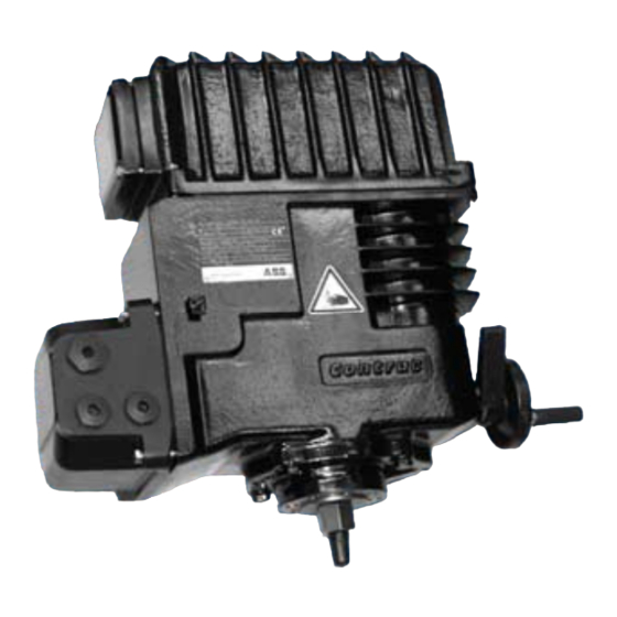
Page 11: Design And Function
Design and function Design and function Fig. 2: LME620-AI/AN (illustrations may differ from actual installation) 1 Cover (for LME620-AI incl. electronic unit) 2 Handwheel 3 Thrust rod 4 Commissioning and service field (ISF) Functionality Actuator for the operation of final control elements with preferably linear movement. The actuator thrust rod transfers the force directly to the final control element. -
Page 12: Installation
Installation Installation Actuator check Before you start to install the actuator make sure that the delivery status corresponds to the ordered status and to the intended use. • Make sure that the motor and the connection chambers are free of dirt, moisture and corrosion. -
Page 13: Valve Requirements
Installation 3.3.1 Valve requirements • The force in the end position can be up to 2.5 times higher than the rated force. Mounting examples Fig. 4: Mounting example LME620-AI/-AN (Contrac) 1 Servo motor 6 Valve stem 2 Handwheel 7 Valve yoke 3 Mounting screws (8.8) 8 Valve 4 External stop... -
Page 14: Electrical Connection
Electrical connection Electrical connection Each actuator requires a Contrac electronic unit which is loaded with the type specific-software. Carefully consider the instructions for the electronic unit and compare the data labels of the actuator and the electronic unit in order to ensure a proper hard- and software assignment. Cable shield 4.1.1 Signal part... -
Page 15: Integrated Electronic Unit Ai (Standard)
Electrical connection Integrated Electronic Unit AI (standard) Important The power and signal cables are connected by universal plug to the integrated actuator electronic unit. Fig. 6 To switch the actuator to automatic mode (AUT), the following conditions must be met: •... -
Page 16: Electronic Unit In Field Mount Ean823 (Standard)
Electrical connection Electronic unit in field mount EAN823 (standard) Important The electrical connection is provided by a plug on the actuator and the terminals on the electronic unit. Fig. 8 To switch the actuator to automatic mode (AUT), the following conditions must be met: •... -
Page 17: Electronic Unit In Field Mount Ean823 (Bus Communication)
Electrical connection Electronic unit in field mount EAN823 (bus communication) Fig. 9: PROFIBUS DP Configuration of digital input/output signals (standard control) 4.6.1 Standard Fig. 10: Potential wiring for default assignments 42/68-273-EN LME620-AI/-AN (Contrac) -
Page 18: Downstream From Step Controller
Electrical connection 4.6.2 Downstream from step controller Fig. 11: Potential wiring for "Downstream from step controller" operation Important When operating the unit downstream from a step controller, the selector switch must be in the position. Important When DI1 is assigned with DC +24 V, the electronic unit is write-protected. LME620-AI/-AN (Contrac) 42/68-273-EN... -
Page 19: Operation
Operation Operation Automatic / manual mode The servo motor triggered by the power electronics controls the axially fixed drive sleeve/nut assembly via grease-lubricated spur gears. A ball bearing screw (see Figure Fig. 12) radially fixed by an anti-twist arrester converts the rotary motion to a linear one. A position sensor detects the current thrust rod position via mechanical reduction gearing without backlash. -
Page 20: Maintenance
Maintenance Maintenance Important All maintenance activities may only be performed by properly qualified persons. Contrac actuators feature a robust construction. As a result, they are highly reliable and require minimal maintenance. The maintenance intervals depend upon the effective load and are therefore not specified here. -
Page 21: Alarms / Errors
Alarms / Errors Alarms / Errors Definition 7.1.1 Alarms The actuator or electronic unit is in a critical state (e.g., high temperature), which currently does not affect the actuator, electronic unit, process or persons. The actuator functions are available. Previous alarms are stored in the "Saved Alarms" area in the electronic unit. The graphic user interface use to output the stored alarms. -
Page 22: Alarm Diagram
Alarms / Errors Alarm diagram Setpoint time-out Transmitter Maintenance Actuator Temperature of Monitoring temperature Electronic Unit upper limit/ lower limit upper limit / Lubricant / (high / low) (high / low) lower limit Elastom. Motor / Gear Monitoring ON Integr. Behavior at critical controller temp. -
Page 23: Error Diagram
Alarms / Errors Error diagram Positioning time-out Hardware Software Monitoring Monitoring Standstill Frequency converter Position sensor memory error Flash end positions error Min. speed RAM error Movement in incorrect direction Watchdog monitoring activated Monitoring ON & Error signal Error message via actual value ON &... -
Page 24: Troubleshooting
Trouble shooting Trouble shooting This chapter only covers hardware-related errors. For additional troubleshooting information, refer to the online help for the operator interface. Error Possible cause Troubleshooting Valve cannot be moved by Failure either on the Disconnect actuator from valve. actuator. -
Page 25: Electrical Test Values
Trouble shooting Electrical test values Fig. 13 Winding resistance ± 5 % at 20 °C (68 °F) Motor L1 (bl.) - L2 (sw): 3,4 Ω L1 (bl.) - L3 (viol.): 3,4 Ω Brake 50 Ω 42/68-273-EN LME620-AI/-AN (Contrac) -
Page 26: Technical Data
Technical data Technical data General information LME620-AI (integrated electronic unit) LME620-AN (separate electronic unit) Operating mode S9 – 100 %; stallproof acc. to IEC 60034-1 / EN 60034-1 Protection Class IP 66 Humidity ≤ 95 % average; condensation not permitted Ambient temperature 55 °C (15 130 °F) -
Page 27: Appendix
10 Appendix 10.1 Permits and certifications Symbol Description CE mark By placing the CE mark on the model plate, ABB Automation Products GmbH declares its conformance with the following directives: EMC directive 89/336/EEC. Machinery directive 2006/42/EC Important All documentation, declarations of conformity and certificates are available in the download area of ABB. - Page 28 Appendix Statement about the contamination of devices and components The repair and/or maintenance of devices and components will only be performed when a completely filled out explanation is present. Otherwise, the shipment can be rejected. This explanation may only be filled out and signed by authorized specialist personnel of the operator.
-
Page 29: Index
Index 11 Index Change from one to two columns Accessibility .............12 Functionality.............11 Actuator check ............12 Actuator electronic unit ..........15 General information ..........26 Adjustments ...............9 General Safety Information........5 Alarm diagram............22 Alarms..............21 Heat sources............12 Alarms / Errors ............21 Inspection and overhaul...........20 Appendix ..............27 Assembly with the valve ..........13 Installation..............12 Installation instructions ..........12... - Page 30 Index Repelling power ..........10, 20 Transport safety information ........8 Returning devices ............8 Trouble shooting ............24 Safety.................5 Valve requirements ..........13 Storage conditions .............9 Visual check.............20 Storage period ............9 Symbols and warnings..........6 Warranty provision .............6 Wear ................20 Technical data............26 WEEE directive ............8 Technical limits ............5 Winding resistance...........25 Time until next maintenance is required....20...
- Page 32 ABB has Sales & Customer Support The Company’s policy is one of continuous product expertise in over 100 countries worldwide. improvement and the right is reserved to modify the information contained herein without notice. www.abb.com/instrumentation Printed in the Fed. Rep. of Germany (09.2008) ©...