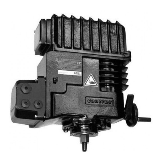
ABB Contrac LME620AI Instructions Manual
Electrical linear actuators for continuous modulating control
Hide thumbs
Also See for Contrac LME620AI:
- User manual (44 pages) ,
- Operating instruction (32 pages) ,
- Service instruction (30 pages)

Related Manuals for ABB Contrac LME620AI


Summary of Contents for ABB Contrac LME620AI
- Page 1 Instructions Electrical Linear Actuators for 42/68 273 EN Continuous Modulating Control LME620AI / LME620AN (Contrac) Rated Force 4 kN...
-
Page 2: Table Of Contents
Content Device Identification ......2 Actuator ID Label 1.1 Actuator ID Label ......2 ID Label of Electronics Antrieb / Actuator: CONTRAC .. -
Page 3: General
2. General 2.1 Proper use Control actuators are intended to be used exclusively for actuating final control elements (valves, vanes, etc.). Do not use these actuators for any other purpose. Otherwise, a hazard of personal injury or of damage to or impairment of the operational reliability of the device may arise. 2.2 Safety and precautions When mounting the actuator in areas which may be accessed by unauthorized persons, take the re- quired protective measures. -
Page 4: Assemblies
5. Assemblies 1: Handwheel 2: Handwheel lock 3: Thrust rod 4: Ext. stop 5. Gearbox 6. Connector plug 7. CSF 8. Cover (for LME 620 AI incl. electronics d0042rxa Figure 1: LME 120 ... 5.1 Operation 5.2 Normal mode The motor triggered by the electronics drives the axially fixed drive sleeve/nut assembly via greased spur gears. -
Page 5: Technical Data
6. Technical data LME 620 AI LME 620 AN Rated force [kN] 4 ... 2 Starting force [Nm] approx. 1.2 x rated force (break-away force in end posi- tions 2 x rated force for a short time) Handwheel force required to 11 N achieve the rated Rated speed [mm(s]... -
Page 6: Mounting The Actuator To The Valve
fastening scrrews thrust rod external limit stop mech. position coupling indicator valve stem valve yoke valve (r00018x1) Figure 2: Mounting LME 620, example 7.3.1 Valve Design Requirements - Consider the end position forces (up to 2.5 x rated force) when designing the valve. 7.4 Mounting the Actuator to the Valve - Completely retract the actuator thrust rod and put the actuator on the valve yoke. -
Page 7: Electrical Connection
8. Electrical Connection Each actuator requires a Contrac electronic unit. Proper actuator operation requires an actuator spe- cific software loaded in this associated electronic unit. See electronic unit instructions for details. Com- pare the data labels on both, electronic unit and actuator, in order to ensure a correct hardware and software assignment. -
Page 8: Separate Electronic Unit Ean823 (Standard)
8.3 Separate electronic unit EAN823 (standard) The electrical connection is done with a combined plug on the actuator and with screw terminals on the electronics. Sub Distribution Board mains ext. (single fuse phase) setpoint transmitter act. value + HART 4..20 mA MAN/AUT MAN (+) MAN (-) ok/fault... -
Page 9: Signal Input And Output (Conventional Triggering)
8.5 Signal input and output (conventional triggering) 8.5.1 Standard Transmitter (Option) 9 10 Electronic Unit (r00358x1) Fig. 7: ** Write-protected when applying +24 V DC to DI 1. 8.5.2 Behind a step controller controller Transmitter (Option) 9 10 Electronic Unit (r00359x1) Fig. -
Page 10: Fuses At Actuator With Integrated Electronic Unit
8.7 Fuses at actuator with integrated electronic unit Fuse type U = 115 V U = 230 V External fuse(extern) 16 A, slow Mains fuse 6.3 A slow 3.15 A slow Low temperature heater (only for low tempera- ture version) Fuse for protection against active 20 mA current 0.04 A (fast) 0.04 A (fast) -
Page 11: Setup
9. Setup The actuator only requires the basic settings (adaptation to the operating range) in order to be operated with the standard or custumer specific configuration. Use the Local Control Panel (LCP) for these set- tings. Use the appropriate configuration software for more detailed parameter changes or diagnosis functions. -
Page 12: Adjustment Using The Configuration Program
9.1.4 Setting 9.1.4.1 “Setting” mode - Set electronics to “setting” mode by pressing both push buttons (3) simultaneously for approx. 5 seconds, until both LEDs (2 + 8) are flashing synchronously at approx. 4Hz. („setting mode“ is the standard electronic unit status after passing the final factory test) 9.1.4.2 Defining first position (0% or 100%) (Higher precision in 2nd position) -
Page 13: Maintenance
10.Maintenance Contrac actuators have a robust construction. As a result, they are highly reliable and require only little maintenance. The maintenance intervals depend upon the effective load and are therefore not specified here. The built-in microprocessor evaluates the actual load factors (e.g. torques, temperatures, etc.) and de- rives the remaining operating time until the next routine maintenance is required. - Page 14 (r00329x1) (r00342x1) Fig. 11:Position sensor Fig. 12:Mounting position (actuator position: thrust rod downward) (r00336x1) Fig. 13:Connecting the ribbon cable plug to the PCB After mounting is completed readjust the actuator range as described in section 10 of this manual.
- Page 15 ABB has Sales & Customer Support The Company’s policy is one of continuous product expertise in over 100 countries worldwide.. improvement and the right is reserved to modify the information contained herein without notice. www.abb.com/instrumentation Printed in the Fed. Rep. of Germany (08.05) ©...