Table of Contents
Advertisement
PROGRAM
PITCH B/ MOD D
AT/ BTH MOD
VELOCITY
MIDI RX CH
MIDI TX CH
0
10
0
DATA
10
CHORUS / DIST
PANNING
ARPEGGIO
UTILITY
VOLUME
PORTAMENTO
EDIT
WRITE
SAVE
MIDI CLOCK
CV / GATE CH
TUNING
PROTECT
ENABLE
SAVE TYPE
TRIGGERING
SAVE
DEMO
COMPARE
WRITE
HEADPHONES
WRITE
DATA ENTRY
AUDITION
MODE
LFO 1 AND 2
OSCILLATORS 1 AND 2
0
10
0
10
50
50
0
12
5
5
5
SPEED
DELAY
DETUNE
SEMITONE
ENV 2 DEPTH
LFO 1 DEPTH
1
2
RDM
TRI SAW SQR
16' 8' 4' 2'
1
2
OFF
ON
LFO SELECT
SHAPE
RANGE
WAVEFORM
OSC SELECT
OSC 1 - 2 SYNC PWM SOURCE
MIXER
FILTER
OSC
1
1
&
2
5
5
5
OFF
OSC
2
0
10
0
10
0
10
5
PULSE WIDTH
OSC LEVEL
LEVEL
FREQUENCY
RESONANCE
LFO 2 DEPTH
ENV 2
MAN LFO 2
NOISE
RING
EXT
12dB
24dB
0
10
0
10
5
SUB OSC
SOURCE
CUT-OFF
K'YBD TRACK
ENV 2 DEPTH
Owners
Manual
ENVELOPE 1 AMPLIFIER
5
0
10
0
10
0
10
0
10
ATTACK
DECAY
SUSTAIN
RELEASE
5
0
10
0
10
0
10
0
10
ENVELOPE 2 FILTER
Advertisement
Table of Contents

Related Manuals for Novation Super Bass Station


Summary of Contents for Novation Super Bass Station
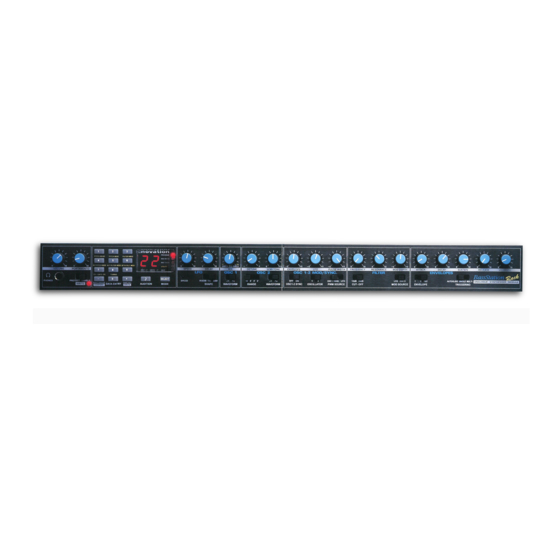
- Page 1 LFO 1 AND 2 PROGRAM PITCH B/ MOD D AT/ BTH MOD VELOCITY MIDI RX CH MIDI TX CH DATA CHORUS / DIST PANNING ARPEGGIO UTILITY VOLUME PORTAMENTO SPEED DELAY EDIT WRITE SAVE MIDI CLOCK CV / GATE CH TUNING PROTECT ENABLE TRI SAW SQR...
-
Page 2: Table Of Contents
Table of Contents Introduction Front Panel Controls Rear Panel Connections Connections & Setting up Applications - Basic Applications - Advanced Selecting Programs / Finder Mode Editing & Writing Programs / Compare Factory & Restoring Factory Programs About Analogue Synthesis Block Diagram Master Volume Section Data Entry / Program Section Keypad... -
Page 3: Introduction
Once “that sound” has been created the Super Bass Station has 150 RAM Program locations to store them in. These plus the 50 ROM programs can be recalled with MIDI Program Change messages. -
Page 4: Front Panel Controls
Front Panel Controls PITCH B/ MOD D AT/ BTH MOD DATA CHORUS / DIST ARPEGGIO VOLUME PORTAMENTO MIDI CLOCK CV / GATE CH PROTECT ENABLE SAVE TYPE TRIGGERING COMPARE HEADPHONES WRITE DATA ENTRY 1 Master Volume Section This section contains the Master Volume control, Portamento / Data Entry control, Headphone output socket and the Program write switch. -
Page 5: Rear Panel Connections
CV /Gate and output from these connectors. 3 Mixer External Audio Input This connector allows external signals to be processed by the Super Bass Station’s filters and envelopes. External signals can also be used as triggers for the envelopes. THRU... -
Page 6: Connections & Setting Up
“Write” switch is in the “Protect” position. Now, connect the power supply ( Novation PSU-4 ) to the socket marked “Power In 9VDC” and plug into a suitable AC power outlet. Switch on the power to the Super Bass Station and the dis- play should now illuminate showing the last selected program number. -
Page 7: Applications Basic
NOTE: This setup does not allow the recording of knob movements on the Computer Software/Sequencer. This is because the MIDI output of the Super Bass Station is not connected to the input of the Sequencer/Computer. To record Knob move- ments in real-time refer Advanced Setup on page 6. -
Page 8: Applications Advanced
Amplifer / Mixer and Monitors This is the advanced way to setup the Super Bass Station and utilises all of the rear panel features. This setup allows real- time recording of knob movements onto the Computer Software/Sequencer as both the MIDI output of the keyboard and the MIDI output of the Super Bass Station are merged with an external (not supplied) MIDI Merge box. - Page 9 Moog The Super Bass Station can also have it’s Arpeggiator Latch parameter switched on and off via MIDI. To do so connect a sustain pedal to the master keyboard. The Super Bass Station reads sustain information as Arpeggiator latch “on” / “off” so depressing the sustain pedal will switch the Arpeggiator latch “on”...
- Page 10 NOTE: This function works independently from the “Level” control in the mixer section. NOTE: If you have the “Triggering” set to “EA” no sound will be heard when MIDI notes are sent to the Super Bass Station until an external signal connected to the external signal input goes past the trigger level set with this parameter. If no exter- nal signal is present or connected and this parameter is set to “On”...
-
Page 11: Selecting Programs / Finder Mode
Pressing the “Audition / Demo” will not only activate the Demo for the category of the sound currently selected but also will engage “Finder Mode”. As an indication that the Super Bass Station is in “Finder Mode” both the Decimal points in the dis- play flash. -
Page 12: Editing & Writing Programs / Compare
Writing a Program into Memory The program memory on the Super Bass Station is divided up as follows: You cannot store programs in the ROM area (“A” Bank 000 - 049) only in the RAM area.( “A” Bank 050 - 099 and “B” Bank 100 - 199) If you edit a factory program, you can save it in one of the 150 user program locations. -
Page 13: Factory & Restoring Factory Programs
Factory Programs The Super Bass Station comes pre loaded with 200 sounds. The first 50 in the “A” bank are ROM sounds ( Read Only Memory ) and these cannot be erased. All the other sounds in banks “A” and “B” are in RAM and can be overwritten or erased. -
Page 14: About Analogue Synthesis
To understand synthesis of sound it is necessary to have some understanding about sound About Analogue itself. Sound is a vibration or Oscillation. These vibrations create changes in air pressure Synthesis that is picked up by our ears and perceived as sound. When dealing with musical sounds the vibrations or oscillations occur at regular intervals and are perceived as the “Pitch”... - Page 15 White noise has no fundamental and all frequencies are at the Volume same level. This waveform can be used by itself to synthesise explosions or wind and when used in conjunction with other Noise Harmonic waveforms can be used to create the illusion of “Breath” in an instrument. The choice of waveform is important because it determines the basic “Timbre”...
- Page 16 A “Piano” can be seen to go to full volume instantly when a key is pressed and then gradual- About Analogue ly falls back down to zero after several seconds. Synthesis Key "On" Key "Off" Volume Time A “String Section” can be seen to go to full volume gradually over several seconds when a key is pressed and then stays there until the key is released when gradually over a couple of seconds the volume drops to zero.
- Page 17 A = Attack time. This is used to adjust the time it takes when a key is pressed for the enve- lope to go from zero to full value and can be used to create “Fade in’s”. D = Decay time. This is used to adjust the time it takes for the envelope to go from full value to the value set by the Sustain level.
- Page 18 effect. An “Envelope Generator” can also be used on the filter so that the “Tone” of a sound About Analogue varies over time. A Feature called “Keyboard Tracking” can also be used on the filter so that Synthesis the “Tone” of a sound changes depending on the note being played. The Amplifier can be manipulated by “Envelope Generators”...
-
Page 19: Block Diagram
Saw Sq Saw Sq Detune Semi Range ÷ 2 Noise Oscillator 1 Sub Osc Oscillator 2 Source Ring Modulator LFO 1 ENV 2 LFO 1 ENV 2 Oscillator Sync On/Off PWM Source PWM Source Sync Breath Sync Pitch IN MIDI Clock IN MIDI Clock IN Breath Clock... -
Page 20: Master Volume Section
Section VOLUME This knob adjusts the overall output volume of the Super Bass Station on both the Main L/R and Headphone outputs. NOTE: This control can be overridden by MIDI Volume data. If a MIDI Volume of “0” has been... - Page 21 “write” over an existing program. Refer: “Writing a Program Into Memory” on page 10. Headphone - Socket HEADPHONES Use this 1/4 jack socket to monitor the output of your Super Bass Station via headphones. This output will drive any type of headphones. Master Volume...
-
Page 22: Data Entry / Program Section
This is where you select the programs on the Super Bass Station, set the MIDI transmit and Data Entry/Program receive channels, set the various utility functions and store newly edited programs. Keypad PROGRAM PITCH B/ MOD D AT/ BTH MOD... -
Page 23: Audition - Auto Trigger Button
Pressing the “Audition / Demo” will not only activate the Demo for the category of the sound currently selected but will also engage “Finder Mode”. As an indication that the Super Bass Station is in “Finder Mode” both the decimal points in the dis- play flash. -
Page 24: Mode Button - Program Banks
MODE 1 - Program Bank A & B. There are 2 “Banks” of 100 sounds in the Super Bass Station. They are divided up as follows: You cannot store programs in the ROM area (“A” Bank 000 - 049) only in the RAM area.( “A” Bank 050 - 099 and “B” Bank 100 - 199) If you edit a ROM program, you can save it in one of the 150 RAM user program locations. -
Page 25: Midi Tx & Rx Channels
MODE 2 - MIDI Receive Channel This is where you set the MIDI receive channel for the Super Bass Station . Use the “Mode” button to select the “MIDI RX Ch.” mode - LED on, and then the “Data Entry” keypad to enter your selection. The recognised numbers in this mode are from “01”... -
Page 26: Utility Mode / Operation
Button 1 - Pitch B / Mod D DataEntry/Program PITCH B/ MOD D Utilities/Pitch/Mod Related groups of parameters are in “Pages” within each button. This buttons parameters are used to determine how the Pitch Bend Joystick / Wheel on your controller keyboard effects the pitch of the oscillators. Pages exist within this button and they are selected by pressing button 1 again. - Page 27 Page 2 - Oscillator 2 Pitch Bend Range PROGRAM MIDI RX CH MIDI TX CH UTILITY EDIT WRITE SAVE Ident This display will alternate between “P2” ident ( Oscillator 2 Pitch Bend Range ) and it’s value. Use the Data Entry / Portamento Rotary control to adjust the value of this parameter.
- Page 28 Use the Data Entry / Portamento Rotary control to adjust the value of this parameter. This Data Entry/Program parameter controls the depth of LFO 1 pitch modulation ( Vibrato ) to both of the oscillators Utilities/Pitch/Mod by the Modulation Joystick/Wheel from the controller keyboard. The range is “oF” to “15”. The higher the value more vibrato is applied at full modulation.
-
Page 29: Button 2 Aftertouch / Breath
Button 2 - AT / Breath Mod AT/ BTH MOD Related groups of parameters are in “Pages” within each button. This buttons parameters are used to determine how Aftertouch and Breath controllers via Midi effect the pitch of the oscillators. Pages exist within this button and they are selected by pressing button 2 again. - Page 30 Page 2 - Oscillator 1 and 2 Breath Pitch Mod Depth Data Entry/Program Utilities/AT/Breath EDIT WRITE Ident This display will alternate between “bP” ident ( Oscillator 1 and 2 Breath Mod Pitch Depth ) and it’s value. Use the Data Entry / Portamento Rotary control to adjust the value of this parameter.
- Page 31 The range is “- 7” to “+7”. The higher the value more filter manipulation is applied at full modulation.This parameter is memorised with the program. Page 4 - Filter Breath Mod Depth PROGRAM MIDI RX CH MIDI TX CH UTILITY EDIT WRITE SAVE...
- Page 32 Use the Data Entry / Portamento Rotary control to adjust the value of this parameter. This Data Entry/Program parameter controls the depth of modulation to the amplifier ( Volume ) by Aftertouch from the Utilities/AT/Breath controller keyboard. The range is “00” to “15”. The higher the value more volume manipula- tion is applied at full modulation.This parameter is memorised with the program.
-
Page 33: Button 3 Velocity
Button 3 - Velocity VELOCITY Related groups of parameters are in “Pages” within each button. This buttons parameters are used to determine how Velocity on received notes via Midi effect the envelope generators and which sound category the program is in. Pages exist within this button and they are selected by pressing button 3 again. -
Page 34: Button 3 Sound Category
Page 2 - Filter Envelope Velocity ( ENV 2 ) Data Entry/Program Utilities/Velocity EDIT WRITE Ident This display will alternate between “VF” ident ( Filter Envelope Velocity Depth ) and it’s value. As you can see from the Block Diagram on page 17 ENV 2 is the envelope that modulates the filter. Use the Data Entry / Portamento Rotary control to adjust the value of this parameter. - Page 35 This display will alternate between “CA” ident ( Sound Category ) and it’s value. Data Entry/Program Utilities/Category Use the Data Entry / Portamento Rotary control to adjust the value of this parameter. This parameter sets which “Category” a sound is in so that the “Finder Mode” can find similar sounds marked with the same category.
-
Page 36: Button 4 Chorus
Button 4 - Chorus / Dist Data Entry/Program CHORUS / DIST Utilities/Chorus Related groups of parameters are in “Pages” within each button. This button is used to access the Stereo Chorus and Distortion parameters. Pages exist within this button and they are selected by pressing button 4 again. Refer to the Ident Map on the outside back cover of this manual for more details. - Page 37 The range is: “OF” = Off or bypassed. No Chorus effect. “1P” = Preset 1( Emulation of Juno 6* Chorus type 1 ) “2P” = Preset 2( Emulation of Juno 6* Chorus type 2 ) “3P” = Preset 3 “4P” = Preset 4 “5P”...
-
Page 38: Button 4 Distortion
This parameter controls the depth of to which the selected LFO waveform will modulate the Data Entry/Program Chorus effect. The range is “00” to “99”. A value of “00” will produce only a slight amount of Utilities/Distortion modulation, producing only a slight swirling stereo sensation. At a value of “50” the chorus effect is quite noticeable and at a value of “99”... -
Page 39: Button 5 Arpeggiator
Button 5 - Arpeggiator ARPEGGIO Related groups of parameters are in “Pages” within each button. This buttons parameters are used to control the Arpeggiator. Pages exist within this button and they are selected by pressing button 5 again. Refer to the Ident Map on the outside back cover of this manual for more details. - Page 40 Page 2 - Arpeggiator Octave Range Data Entry/Program Utilities/Arpeggio EDIT WRITE Ident This display will alternate between “Or” ident ( Arpeggiator Octave Range ) and it’s value. Use the Data Entry / Portamento Rotary control to adjust the value of this parameter. This parameter controls the number of octaves the Arpeggiator will sweep through.
- Page 41 The range is: Data Entry/Program Utilities/Arpeggio “UP” This is a pattern where the arpeggio starts at the lowest note you play and sweeps “up” through the notes until it reaches the highest note. It then starts at the bottom again. “dn”...
- Page 42 Note: All the patterns contain velocity data. For details on each pattern see “Factory Pattern Data Entry/Program Data” on the separate sheet. This parameter is memorised with the program. Utilities/Arpeggio Page 4 - Arpeggiator Latch EDIT WRITE Ident This display will alternate between “AL” ident ( Arpeggiator Latch ) and it’s value. Use the Data Entry / Portamento Rotary control to adjust the value of this parameter.
- Page 43 Arpeggiator latch “on” and releasing the sustain pedal will switch Arpeggiator latch “off”. For this to work properly the master keyboard should be transmitting on the same MIDI channel as the RX channel of the Super Bass Station.
-
Page 44: Button 6 Panning
This parameter controls the way in which the Arpeggiator resets itself when new notes are Data Entry/Program played. The range is: Utilities/Panning “oF” This means that the cycle of the sweep of the Arpeggiator is not interrupted when new keys are pressed on the controller keyboard, the Arpeggiator will simply change the notes to the new ones. - Page 45 Page 1 - Pan Mod Source Select PROGRAM MIDI RX CH MIDI TX CH UTILITY EDIT WRITE SAVE Ident This display will alternate between “Pn” ident ( Pan Mod Source Select ) and it’s value. Use the Data Entry / Portamento Rotary control to adjust the value of this parameter.
-
Page 46: Button 7 Midi Clock
Page 2 - Pan Mod Depth Data Entry/Program Utilities/MIDI Clock EDIT WRITE Ident This display will alternate between “Pd” ident ( Pan Mod Depth ) and it’s value. Use the Data Entry / Portamento Rotary control to adjust the value of this parameter. This parameter controls the depth of the panning modulation. The range is “00” to “99”. - Page 47 Page 1 - LFO 1 MIDI Clock Sync PROGRAM MIDI RX CH MIDI TX CH UTILITY EDIT WRITE SAVE Ident This display will alternate between “L1” ident ( LFO 1 MIDI Clock Sync ) and it’s value. Use the Data Entry / Portamento Rotary control to adjust the value of this parameter.
- Page 48 When in any position except “oF” the LFO will sync to incoming MIDI Clock and will follow tempo changes on the sequencer. Be sure to send MIDI Clock in this mode. If the Super Bass Station does not receive MIDI Clock the LFO will appear to be stuck / not functioning.
- Page 49 Use the Data Entry / Portamento Rotary control to adjust the value of this parameter. This parameter controls if LFO 2 runs on it’s internal clock or synchronises to LFO 1. The range is: “oF” = Off. LFO 2 is running on Internal Clock. “-7”...
- Page 50 In this case the “Speed” Rotary for LFO 1 and 2 will have no effect. When this parameter is in the range of “02” to “99” the LFO is synced to incoming MIDI Clock. If this is the case and the Super Bass Station does not receive MIDI Clock the LFO’s will appear to be stuck / not functioning.
- Page 51 Page 3 - Arpeggio Sync PROGRAM MIDI RX CH MIDI TX CH UTILITY EDIT WRITE SAVE Ident This display will alternate between “Ar” ident ( Arpeggio Sync ) and it’s value. Use the Data Entry / Portamento Rotary con- trol to adjust the value of this parameter. This parameter controls if the Arpeggiator runs on it’s internal clock or synchronis- es to LFO 1 or incoming MIDI Clock.
- Page 52 “ 6” = Data Entry/Program “ 7” = Utilities/MIDI Clock “02” = “03” = “04” = “06” = “08” = “09” = “12” = “16” = “18” = “24” = “32” = “36” = “48” = “72” = “96” = “97”...
- Page 53 When this parameter is in the range of “02” to “99” the Arpeggiator is synced to incoming MIDI Clock. If this is the case and the Super Bass Station does not receive MIDI Clock the Arpeggiator will appear to be stuck / not functioning. A lot of software sequencers default to NOT transmitting MIDI Clock.
- Page 54 Page 5 - Trigger Sync Data Entry/Program Utilities/MIDI Clock EDIT WRITE Ident This display will alternate between “tS” ident ( Trigger Sync ) and it’s value. Use the Data Entry / Portamento Rotary control to adjust the value of this parameter. This parameter controls which LFO’s or if the Arpeggiator is the clock for the Analogue Trigger output.
- Page 55 Page 6 - Trigger Type PROGRAM MIDI RX CH MIDI TX CH UTILITY EDIT WRITE SAVE Ident This display will alternate between “tt” ident ( Trigger Type ) and it’s value. Use the Data Entry / Portamento Rotary control to adjust the value of this parameter. This parameter controls which type of trigger signals are output by the Trigger Output. The range is: “00”...
-
Page 56: Button 8 Cv / Gate Channel
Button 8 - CV / Gate Ch Data Entry/Program CV / GATE CH Utilities/CV/Gate Related groups of parameters are in “Pages” within each button. This button is used to access the CV / Gate Interfaces parameters. Pages exist within this button and they are selected by pressing button 8 again. Refer to the Ident Map on the outside back cover of this manual for more details. - Page 57 There are several differing standards of CV / Gate interfaces. Most manufacturers had there own system and they are incompatible. The Super Bass Station’s CV / Gate outputs can be configured to any of the 3 differing standards using this parameter.
-
Page 58: Button 9 Tuning
This display will alternate between “tn” ident ( Tuning ) and it’s value. Use the Data Entry / Portamento Rotary control to adjust the value of this parameter. The Super Bass Station defaults to A = 440Hz so you will not normally need to adjust the tuning. - Page 59 Page 1 - ENV Triggering PROGRAM MIDI RX CH MIDI TX CH UTILITY EDIT WRITE SAVE Ident This display will alternate between “tr” ident ( Triggering ) and it’s value. Use the Data Entry / Portamento Rotary control to adjust the value of this parameter. This parameter controls how the envelopes trigger. The range is: “Lt”...
- Page 60 “P1” Preglide 1. Data Entry/Program Envelopes are retriggered as in the “Lt” setting and when they do retrigger a glide from two Utilities/Triggering semitones down is applied to the oscillators. The time it takes to do this is determined by the setting of the Portamento Control in the “Program Mode”.
- Page 61 Page 2 - LFO Triggering EDIT WRITE Ident This display will alternate between “Lt” ident ( LFO Triggering ) and it’s value. Use the Data Entry / Portamento Rotary con- trol to adjust the value of this parameter. This parameter controls how the LFO’s trigger. The range is: “on”...
- Page 62 NOTE: If you have the “ENV Triggering” parameter set to “EA” no sound will be heard when MIDI notes are sent to the Super Bass Station until an external signal connected to the external signal input goes past the trigger level set with this parameter.
-
Page 63: Factory Demo
Pressing the “Audition / Demo” in “Program” Mode will not only activate the Demo for the category of the sound currently selected but also will engage “Finder Mode”. As an indication that the Super Bass Station is in “Finder Mode” both the Decimal points in the display flash. -
Page 64: Saving System Exclusive Data Dumps
“Sb” Save a single program in BassSation Kybd Format “SR” and “SB” modes should only be used when transferring data from the Super Bass Station to a BassStation Rack or BassStation keyboard. Ensure that your data storage device is ready to accept the data. Use the “Mode” button to select “SAVE” mode - LED on, the display shows: “SS”... -
Page 65: Loading System Exclusive Data Dumps
“Sb” NOTE: A lot of features on the Super Bass Station are not on the BassStation Keyboard and therefore will not be used. For example if the program you wish to transfer to the BassStation Keyboard uses new features, any of the parameters that are not present on the BassStation Keyboard will be deleted and the sound will not be the same. -
Page 66: All Programs
2 If you want to listen to a program before committing it to memory, select the “Program” Data Entry/Program mode ( don”t worry about which program number comes up ). Ensure that the “Write” switch Load Sysex is in the “Protect” position and then transmit the sysex dump from your computer. The “Edit” LED on the display will come on to show that the program available is different to the one displayed i.e. - Page 67 The LFO (Low Frequency Oscillator) produces regular electronic variations which are too low to be heard when converted into audio vibrations. However, they can be used to modify various elements of the sound, producing regular changes in pitch (vibrato), pulse width or filter Cut-Off ( two different controls on the harmonic content of the sound ).
- Page 68 3. Select the 24dB mode and turn the Frequency knob fully anticlockwise - Filter closed. LFO 1 and 2 4. Set the “LFO” and “ENV 2” knobs to zero ( knob in central position ). Section 5. Set the “Filter Mod Depth” parameter in Utilities Mode button 1 page 4 to 15. The mod wheel now controls the filter.
-
Page 69: Lfo 1 And 2 Section
TRI - Short for Triangle, this waveform gives the smoothest, continuous change in level to LFO 1 and 2 the LFO and is therefore probably the most generally useful setting. When routed to Pitch, it Section gives you vibrato (if used with higher speed and lesser depth) or a siren effect (with lower speed and greater depth). -
Page 70: Oscillator 1 And 2 Section
Each oscillator is a sound source producing the electronic equivalent of the vibration in the air which makes a sound The loudspeakers you are using to listen to the Super Bass Station convert the electronic signal into an acoustic one you can actually hear. - Page 71 Pulse ( Including Square ) This waveform switches between maximum and minimum values, giving the blocky look to the waveform. The harmonic content of the pulse waveform is dependent on the relative width of the maximum and mini- mum values. If these are equal, then the waveform is referred to as a square wave and has a very similar harmonic content to a clarinet, i.e.
- Page 72 the human voice. You will find this easier to understand if you set up a very drastic ( and Oscillator 1 and 2 probably unmusical ) pitch change effect just on oscillator 2 using ENV 2 before you switch Section Osc 1-2 Sync on and then switch the sync on and off to hear the difference.
- Page 73 Oscillator 1. Turning the knob in a clockwise direction will make Oscillator 2 increasingly "Sharp" . Slight detunings will enrich the sound by introducing a beating between the oscilla- tors (in the same way a 12-string guitar sounds richer than a 6-string) allowing you to “fat- ten”...
- Page 74 LFO - Rotary Oscillator 1 and 2 Section LFO 1 DEPTH This knob controls the amount of pitch modulation to the oscillator, i.e. how much above and below the set pitch the oscilla- tor regularly rises and falls. If the LFO is set to Triangle wave and it's speed is above the centre of its range, then this will normally produce a vibrato effect, but other effects like a siren or seagull cries are possible with more extreme settings.
-
Page 75: Mixer Section
This knob controls the volume of the Sub oscillator. All the way anticlockwise will give you no signal. In this position and with all the other Mixer levels turned down the Super Bass Station's filter can be heard without the oscillators. As the knob is turned clockwise, the Sub Oscillator will be gradually introduced. - Page 76 This knob controls the volumes of the three sound sources selected by the “Source” switch. All the way anticlockwise will give you no signal. in this position and with all the other Mixer levels turned down the Super Bass Station's filter can be heard without the oscillators.
-
Page 77: Filter Section
(fully anticlockwise). If ever the BassStation is making no sound at all and the Volume knob is turned up, the most likely cause is that the Filter is fully closed. - Page 78 Off frequency, but as you turn clockwise this frequency will be boosted until fully anticlockwise it goes in to oscillation pro- ducing a new pitched element (similar to feedback on an electric guitar). If ever the BassStation produces a high whistling sound, the chances are this knob is too far clockwise.
- Page 79 LFO 2. NOTE : External audio can be processed by the Super Bass Station’s filters and effects. Refer to page 6 “Advanced Applications” for more details on connection and operation.
-
Page 80: Envelope 1 And 2 Section
The envelopes are used to shape the sound over time. Envelope 1 is hard-wired' to ampli- Envelopes 1 and 2 tude or volume. It is used to decide how quickly the sound starts when you hit a note and Section how it sustains or dies away. - Page 81 Sustain - Rotary SUSTAIN This knob sets the level at which the envelope remains after the Decay phase until the note is released. Fully anticlockwise the envelope will decay all the way to zero without being interrupted. As the knob is moved clockwise, the level at which the decay is halted increases until fully clockwise, there is no decay at all.
-
Page 82: Midi Implementation
MIDI Implementation... -
Page 83: Controller Map
MIDI Controller Maps... -
Page 84: Troubleshooting Guide
You will have to enter two controllers with specific values and then a program change message, all with the right values and in the right order and on the right channels. If the message you send does not change the bank on the Super Bass Station then you are not sending the right messages and values. -
Page 85: Specification
Specifications... - Page 86 DECAY SELECT CONGA SELECT SELECT The Novation DrumStation faithfully recreates all the classic sounds of the TR909 and TR808 drum machines and adds new features like Panning, Front Cut and a built in distortion for each drumsound. Available Autumn 1997...
-
Page 87: Fcc Information ( U.s.a.)
Specifications subject to change: The information contained in this manual is believed to be correct at the time of going to press. However, Novation reserves the right to change or modify the specification without notice or obligation to update existing units. -
Page 88: Ident Map
PROGRAM PROGRAM MIDI RX CH MIDI RX CH MIDI TX CH MIDI TX CH UTILITY UTILITY EDIT WRITE SAVE EDIT WRITE SAVE PITCH B/ MOD D Osc1 Pitch Bend Range Osc2 Pitch Bend Range PROGRAM PROGRAM MIDI RX CH MIDI RX CH MIDI TX CH MIDI TX CH UTILITY...
Need help?
Do you have a question about the Super Bass Station and is the answer not in the manual?
Questions and answers