Table of Contents
Advertisement
Advertisement
Table of Contents

Related Manuals for Bruker D2 PHASER


Summary of Contents for Bruker D2 PHASER
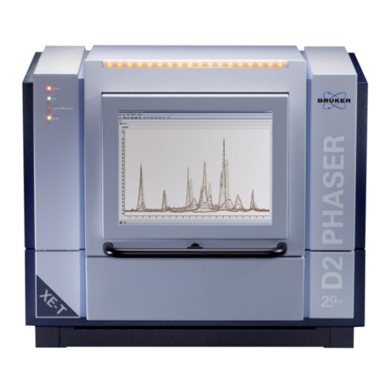
- Page 1 D2 PHASER User Manual Original Instructions Innovation with Integrity...
- Page 2 All configurations and specifications are subject to change without notice. Order no. DOC-M88-EXX141 V5. Updated: Jan 30, 2015. © 2009 - 2015 Bruker AXS GmbH, Karlsruhe, Germany. All trademarks and registered trademarks are the sole property of their respective owners.
-
Page 3: Table Of Contents
User Manual D2 PHASER User Manual Caution! Read the manuals ‘D2 PHASER Introductory User Manual’ and ‘D2 PHASER – From Unpacking to the First Measurement – Quick Start Guide’ completely before switching on the D2 PHASER instrument. Table of contents Introduction ........................ - Page 4 D2 PHASER Alignment of the diffractometer ................15 Introduction ........................... 15 Philosophy of alignment for D2 PHASER systems ..............15 Functional principle of the goniometer ..................16 Zero definition of the scale ....................16 ...
- Page 5 D2 PHASER User Manual Tables and constants ....................36 Figures........................37 DOC-M88-EXX141 V5 – 01.2015...
- Page 6 User Manual D2 PHASER (intentionally left blank) DOC-M88-EXX141 V5 – 01.2015...
-
Page 7: Introduction
X-ray diffractometer desktop system (fig. 1, fig. 2) with a compact all-in-one desktop design. The D2 PHASER is easy in operation and has a very small footprint (fig. 2). It is a high quality XRD system with innovative high end design which works without any external components, i.e. chiller, computer system, display etc. - Page 8 6. Standard Bragg Brentano geometry with fixed primary (a) and linear (position sensitive) LYNXEYE counter (c) for fastscan measurements as shown in fig. 7 (D2 PHASER with sample changer see fig. 141). Standard Bragg Brentano geometry with fixed primary (a) and secondary slit modules (b) and an energy dispersive XFlash detector (c) for monochromatic measurements and basic qualitative element analyses, as shown in fig.
-
Page 9: Basics And Principle Of Operation
D2 PHASER User Manual Basics and principle of operation The operation mode, which is described here in principle, is called the focussing Bragg Brentano geometry. Radiation from the X-ray tube (e) (fig. 9 and 10) is emitted from the focus (f) and hits the sample in the goniometer centre (a). -
Page 10: Design Of The Diffractometer
Sealed X-ray tubes ((a) in fig. 14) with line focus (12mm x 0,4mm), earthed anode and ceramic body are used in D2 PHASER systems. They are energized with power of an X-ray generator ((g) in fig. 14 and (c) in fig. 16) which is installed in the back part of the system housing. X-ray diffraction tubes are available with Cr, Co and Cu anode. - Page 11 D2 PHASER User Manual electronics and there is a further temperature increases over 68°C there is a thermofuse (fig. 143) which will melt at 86°C (±5°C) and switch off the HV generator in order to protect the system by overheating.
-
Page 12: Slit Systems, Slit And Soller Modules And Other Passive Optics
User Manual D2 PHASER Slit systems, slit and Soller modules and other passive optics There are slit systems for the primary and secondary beam path. The primary slit system is able to hold one slit module - the divergence slit module - and one axial Soller module. The secondary slit system for 0D-detectors (scintillation counter and XFlash detector) is more complex and can hold the antiscatter slit module, the secondary Soller module and the detector slit module. -
Page 13: K Filter Module
D2 PHASER User Manual (cut corner) which indicates the edge to which the slit edges are precisely adjusted ((b) in fig. 31). Insert the slit modules in the orientation as shown in fig. 31 and fig. 33. The slit modules are fixed magnetically (fig. -
Page 14: Sample Holder
Do not loosen these screws because the sample holder’s alignment will become lost. Fans provide the interior of the D2 PHASER with fresh cooling air from the environment. An overpressure is created inside the instrument which is relieved through the ventilation slots. When the front door is opened, air flows from the inside to the outside of the housing through the front door. -
Page 15: Silicon Strip Detector Lynxeye
X-ray energy from 6keV to 15keV is provided. The factory settings are optimized for Cu-K. The LYNXEYE fits perfectly for D2 PHASER systems. There is no need for counting gas, cooling water or liquid nitrogen, making the LYNXEYE a compact, robust and maintenance free detector. -
Page 16: Operation Of The D2 Phaser
Place the D2 PHASER in such a way that you sit directly in front of the display and the keyboard. The TFT display should be at eye level or slightly lower. Tilt the TFT screen up or down (fig. 101 and fig. -
Page 17: Switching Off The Instrument
For the time interval of a measurement, the ‘busy’ LED indicates that the instrument is busy with measurement. The long LED array on the upper front corner of the D2 PHASER ((a) in fig. 113) indicates that HV is on (X-ray on). This array is bright and visible from a greater distance. -
Page 18: Configuration And Settings Of Primary Section
User Manual D2 PHASER This table lists the most important reflections with line positions in 2 for Cu radiation = 0.154060 nm). The certified reference material to be used is based on Bruker AXS’s inhouse K1 corundum standard reference material. -
Page 19: Configuration And Settings Of Secondary Section
D2 PHASER User Manual shown here as an example (corundum (c) in fig. 25 or in (a) of fig. 144 for sample changer). Move 2- angle to 60° (sample exchange position), open the instrument’s door, pull down the spherical handle of the sample holder lift ((b) in fig. -
Page 20: Start Measurement With Joblist
DIFFRAC.MEASUREMENT.SUITE ‘commander’. Start element analyses with the program SPECTRA A D2 PHASER which is equipped with an XFlash detector additionally allows easy qualitative element analyses: The XFlash detector can detect elements with excitation energies up to 20keV and hence provides valuable information on the composition of a sample which, for instance, make qualitative phase analyses more simple and straightforward. -
Page 21: Alignment Of The Diffractometer
In the following, each system which is limiting or shaping X-ray radiation, is called an X-ray optical system or X-ray optics. The optical systems which are used for the D2 PHASER may be slit modules, absorber modules and filter modules but no monochromators or other crystals. -
Page 22: Functional Principle Of The Goniometer
D2 PHASER user alignment with 1D-detector (LYNXEYE) and standard sample holder or sample changer The primary Soller and slit holder system is preset and aligned at Bruker AXS factory and fixed with a sealed screw (X-ray radiation safety!). The beam will pass a 0.1mm slit and the glass slit simultaneously at zero position (fig. -
Page 23: Setting The Parameters Of The Detector Unit
D2 PHASER user alignment with 0D-detector (Scintillation Counter and XFlash detector) and standard sample holder The primary and secondary Soller and slit holder system is preset and aligned at Bruker AXS factory and fixed with a sealed screw (X-ray radiation safety!). The beam will pass the primary 0.1mm slit, the glass slit and a secondary 0.1mm antiscatter slit or receiving slit, respectively, simultaneously at zero... - Page 24 Parameters 2 and 3 have to be determined under X-ray radiation. They depend on the radiation (wavelength) and the detector type of your D2 PHASER. The determination of the parameters may be done using the interactive program module commander of DIFFRAC.MEASUREMENT Suite. After the parameter determination is finished, they are stored in the configuration file on the hard disk of the computer on which DIFFRAC.MEASUREMENT Suite runs.
-
Page 25: Avoiding Collisions With The D2 Phaser Goniometer
Problem or Error Pattern In case of removing the direct beam stop absorber module at the sample holder of the D2 PHASER, it may happen that the fixing screws (fig. 134) are not totally removed or not tightened anymore. As a consequence the screw could cause a collision with the secondary slit system of scintillation counter or XFLASH installations (fig. -
Page 26: Maintenance Of The Diffractometer
Thermomodule The thermomodule (fig. 143) replaces the flow sensor since introduction of the “D2 PHASER 2 Generation”. It ist mounted on the tube head (fig. 142) to protect the system from overheating. -
Page 27: Refilling The Cooling Fluid Tank
Refill the cooling fluid tank: Close all programs, shut down OS and switch off the system as described before. Disconnect the D2 PHASER system completely from the mains power supply (risk of electric shock). Remove screws (a) and (b) in fig. 79 and …... -
Page 28: X-Ray Safety Precautions
X-ray radiation of each single D2 PHASER instrument prior to delivery under worst case conditions. The D2 PHASER is in compliance with the requirements for X-ray systems which are certified as complete protection instrument (“Vollschutzgerät”) according to the German X-ray standards called “Röntgenverordnung”... - Page 29 D2 PHASER User Manual undercurrent, arc … (etc.) (as a result of the generators self diagnosis) breaks SL1 using the forcibly guided relay K1. There are two voltage dividers inside the generator (HV-Monitor-A/B). The safety controller checks both of these HV divider values simultaneously and breaks SL1 by relay K1 if one of them indicates overvoltage (>34kV).
-
Page 30: Radiation Protection And Leakage Levels
“red and white cross” icon. Generation of X-ray is prohibited in this state. Even after a restart of the D2 PHASER, it will stay in this state to protect the operator. After checking and removing the error condition, the Safety System needs to be reset to return to normal operation. -
Page 31: Important Information For Canadian Users
General Safety Precautions of the D2 PHASER Danger! X-Ray Radiation The D2 PHASER spectrometer system is an analytical instrument with a strong X-ray source. Shielding and safety equipment guarantee that the emitted radiation does not exceed 1.0 μSv/h during operation. -
Page 32: Tissue Sensitivity
User Manual D2 PHASER Tissue Sensitivity In general, the radiation sensitivity of a tissue is: proportional to the rate of proliferation of its cells inversely proportional to the degree of cell differentiation For example, the following tissues and organs are listed from most radiosensitive to least... -
Page 33: Continuous Spectrum
D2 PHASER User Manual converted into X-rays. The anode consists of a metal (for example, Rh, Mo or Cr) that produces a characteristic wavelength. A water cooling system prevents it from overheating. X-ray tubes usually have a thin Beryllium windows by which the X-rays escape to the outside. The tube is partly clad with a heavy absorbing material such as lead to prevent the X-rays emitted in other directions from penetrating to the outside. -
Page 34: Characteristic Spectrum
User Manual D2 PHASER Characteristic Spectrum High-energy electrons can also interact with the atoms of the metal target to produce another type of radiation called “characteristic” radiation because the wavelengths of the photons emitted are characteristic of the anode metal. - Page 35 D2 PHASER User Manual Fig. d: Subshells and their transferred electrons. In Fig. e below, the wavelength distribution of both continuous and characteristic radiation is shown as a function of intensity or the number of pulse counts per second. The characteristic peaks Kα...
-
Page 36: X-Ray Safety Precaution
(300W at 30 kV) in worst case settings (largest opening of primary optics and strongly isotropic scattering sample or beam direction directly to the wall of the housing). Fig. f: Front view of D2 PHASER with emergency stop button. DOC-M88-EXX141 V5 – 01.2015... -
Page 37: Troubleshooting
Troubleshooting Resetting the Safety System In case of problems with the Safety System, please see section Resetting the D2 PHASER Safety System in this User Manual and Replacement of the Fan Filter in the Introductory User Manual. Overtemperature Safety Shutdown In case of X-ray tube overtemperature the HV generator shuts down in order to protect the system. -
Page 38: Dsp Error With Xflash Detector
User Manual D2 PHASER DSP Error with XFlash Detector If the program SPECTRA displays a DSP Time Out, please select Menu Device Connect. After 5 seconds, the system will work again. Other problems In case of other problems, please inform the Customer Service. -
Page 39: Maintenance Parts And Consumables
O-Ring reservoir cap BUK-E07-00016 Fan filter, 120mm K110C160 Reservoir cap K220C31 Cone Handhold K110C144 Buckler for Ø 8,5 Maintenance kit for D2 PHASER systems Coolant, 0,5L Kühlflüssigkeit, 0,5Liter K140C32 PH-indicator strips non bleeding PH-Indikatorstäbchen nicht blutend K320-C13 DOC-M88-EXX141 V5 – 01.2015... - Page 40 User Manual D2 PHASER O-Ring X-Ray-tube mount O-Ring Röhrenhalterung C71121-Z100-A22 O-Ring reservoir cap O-Ring Deckel Vorratsbehälter K200C50 Fan filter, 120mm Filtermatte mit Abdeckung BUK-E07-00016 DOC-M88-EXX141 V5 – 01.2015...
- Page 41 D2 PHASER User Manual Reservoir cap Deckel Vorratsbehälter K110C160 Cone Handhold Konusgriff K220C31 Buckler for Ø 8,5 Stopfen für Ø 8,5 K110C144 DOC-M88-EXX141 V5 – 01.2015...
- Page 42 User Manual D2 PHASER Tables and constants Characteristic Parameters of some Typical X-Ray Source Parameters Cu Kupfer Z=29, A=63,546, ρ=8,94 g/cm, [Ar]3d10 4s1 Linie Transition E(eV) I/Iα1 Γ K-LII 8028 51,2 α K-LIII 8048 α K-MII 8903 6,21 β K-MIII...
- Page 43 D2 PHASER User Manual Figures Fig. 1 Mounted handles for transportation of the D2 PHASER system. Fig. 2 D2 PHASER in use with opened door. DOC-M88-EXX141 V5 – 01.2015...
- Page 44 User Manual D2 PHASER Fig. 3 1D LYNXEYE detector for high speed measurements. Fig. 4 Example of an XRD sample (corundum plate) in standard sample ring. DOC-M88-EXX141 V5 – 01.2015...
- Page 45 D2 PHASER User Manual Fig. 5 Inserting a sample into the sample holder of the D2 PHASER. Fig. 6 Standard Bragg-Brentano setup with primary (a) and secondary slit system (b) and scintillation counter tube (c). Screws (d) for cover of the primary slit holder system.
- Page 46 User Manual D2 PHASER Fig. 7 Bragg-Brentano setup with primary (a) slit system, sample holder (b) and high speed 1D- LYNXEYE detector (c). Fig. 8 Bragg-Brentano setup with primary (a) slit system, sample holder, secondary slit system (b) with antiscatter slit and detector receiving slit, and XFlash detector (c).
- Page 47 D2 PHASER User Manual Fig. 9 (a) goniometer centre, (b) primary beam direction, (c), goniometer, (d) measuring circle, (e) x-ray tube, (f) x-ray focus, (g) divergence slit, (h) primary side, (i) secondary side, (j) sample rotation axis, (k) 1D-detector, Bragg angle, 2 diffraction angle....
- Page 48 User Manual D2 PHASER Fig. 10 (a) goniometer centre, (b) primary beam direction, (c), goniometer, (d) measuring circle, (e) x-ray tube, (f) x-ray focus, (g) divergence slit, (h) primary side, (i) secondary side, (j) sample rotation axis, (k) 0D-detector, Bragg angle, 2 diffraction angle, (l) detector slit, (n) antiscatter slit.
- Page 49 User Manual Fig. 11 Sample rotation axis (j) perpendicular to the sample surface. Fig. 12 Goniometer of D2 PHASER with tube (c), sample holder (d), 1D-detector LYNXEYE (e), goniometer base plate (b) and goniometer mounting plate (a). DOC-M88-EXX141 V5 – 01.2015...
- Page 50 Fig. 14 Top view on the D2 PHASER with tube (a), sample holder (b) and detector (c) in the radiation section. In the electronic system section there are the control board (d), connection plug board (e), safety board (f) and HV generator (g).
- Page 51 D2 PHASER User Manual Fig. 15 Thermomodule composed of NTC-sensor (b) and irreversible thermofuse (a) Fig. 16 Back view on the electronic system section with safety board (a), control board (b) and HV generator (c). DOC-M88-EXX141 V5 – 01.2015...
- Page 52 User Manual D2 PHASER Fig. 17 Primary slit holder system mounted on the tube housing. Fig. 18 Primary slit holder system with inserted slit and Soller and open lid. DOC-M88-EXX141 V5 – 01.2015...
- Page 53 D2 PHASER User Manual Fig. 19 Soller module for 5° (a) and 2.5° (b). Some slit and absorber modules (d). Fig. 20 2.5° Soller module in detail. DOC-M88-EXX141 V5 – 01.2015...
- Page 54 D2 PHASER Fig. 21 Secondary slit system for 0D-detectors (scintillation counter and XFlash detector) mounted on the secondary arm of the D2 PHASER. Screws (d) for the cover of the secondary slit holder system. Fig. 22 Unmounted slit system for 0D-detectors (scintillation counter and XFlash detector).
- Page 55 D2 PHASER User Manual Fig. 23 Opened secondary slit system for 0D-detectors (scintillation counter and XFlash detector). Fig. 24 Opened secondary slit system for 0D-detectors (scintillation counter and XFlash detector) with slit and absorber modules (a), (c) and (d). (b) is the position for Soller modules.
- Page 56 User Manual D2 PHASER Fig. 25 Soller modules for 5° and 2.5° (b) and corundum sample in sample ring (c). Fig. 26 Soller module (a), slit module (b) and absorber/filter modules (c) (d) for LYNXEYE detector. DOC-M88-EXX141 V5 – 01.2015...
- Page 57 D2 PHASER User Manual Fig. 27 Soller module (a) in its position of the LYNXEYE detector. Fig. 28 Positions (a) and (b) in LYNXEYE detector for slit, absorber and filter modules. DOC-M88-EXX141 V5 – 01.2015...
- Page 58 User Manual D2 PHASER Fig. 29 Soller module (a) in its position of the LYNXEYE detector and position (b) for absorber, slit or filter modules. Fig. 30 Primary slit system with slit module inserted. (a) is the primary beam stop unit which protects the detector against radiation damages, (b) is the lift handle for the sample holder.
- Page 59 D2 PHASER User Manual Fig. 31 Slit module with indication of slit width (a) and mark (b). Fig. 32 Absorber/filter module for LYNXEYE detector. DOC-M88-EXX141 V5 – 01.2015...
- Page 60 User Manual D2 PHASER Fig. 33 User inserting a primary slit module. Fig. 34 User inserting a filter module into the LYNXEYE detector. DOC-M88-EXX141 V5 – 01.2015...
- Page 61 D2 PHASER User Manual Fig. 35 Secondary slit system for 0D-detectors with antiscatter slit (a), absorber (b), detector slit (c) and Soller (d) modules. Fig. 36 Soller module for LYNXEYE detectors. DOC-M88-EXX141 V5 – 01.2015...
- Page 62 User Manual D2 PHASER Fig. 37 User inserting a Soller module into holder of the LYNXEYE. Fig. 38 Correct position of an absorber module (a) in the LYNXEYE slit holder. DOC-M88-EXX141 V5 – 01.2015...
- Page 63 D2 PHASER User Manual Fig. 39 Airscatter screen module for standard sample holder with different sides (a) and (b) for different ranges. Fig. 40 User attaching the airscatter screen module onto the magnetic holder. DOC-M88-EXX141 V5 – 01.2015...
- Page 64 User Manual D2 PHASER Fig. 41 Sample holder which is fixed by 4 screws (a), (b), (c) and (d). Fig. 42 Plugs from LYNXEYE detector, data plug (a) and power plug (b). DOC-M88-EXX141 V5 – 01.2015...
- Page 65 D2 PHASER User Manual Fig. 43 LYNXEYE detector window (a). Don’t touch the window because of high voltage HV (120V)! Fig. 44 The two different sides of the airscatter screen module with a < b. DOC-M88-EXX141 V5 – 01.2015...
- Page 66 Scan with radiation from focus (a) through the glass slit module (b) with opened scintillation counter (c). Setting of primary (e) and secondary slit modules (f) (g) in zero position with special Bruker AXS alignment tool. DOC-M88-EXX141 V5 – 01.2015...
- Page 67 D2 PHASER User Manual Fig. 46 Scan with radiation from focus (a) through glas slit module (b) and LYNXEYE (c) in 0D- mode (all channels open). Determination of centre channel which is hit through the glass slit module (f). Primary slit module (e) must be set so that the beam passes the glass slit module (f).
- Page 68 User Manual D2 PHASER Fig. 47 Set LYNXEYE 0D-mode window opening in mm. Fig. 48 Glas slit module for reference alignment. DOC-M88-EXX141 V5 – 01.2015...
- Page 69 D2 PHASER User Manual Fig. 49 User inserting glas slit module into the sample holder. Fig. 50 Move glass slit module into beam direction. DOC-M88-EXX141 V5 – 01.2015...
- Page 70 User Manual D2 PHASER Fig. 51 Turn the sample holder ring so that the beam groove is in beam direction. Fig. 52 User lifting sample holder into measuring position. DOC-M88-EXX141 V5 – 01.2015...
- Page 71 D2 PHASER User Manual Fig. 53 Correct position of sample holder ring with beam groove and glas slit module. Fig. 54 Reference scan with 0D-mode and wide opened detector window (type of detector, scan mode and peak shape differ for D2 PHASERs with scintillation counter).
- Page 72 User Manual D2 PHASER Fig. 55 Window for reference and offset determination. Fig. 56 Direct beam through the glas slit module measured with LYNXEYE 0D-mode and wide detector opening. (Type of detector, scan mode and peak shape differ for D2 PHASERs with SC-detector.)
- Page 73 D2 PHASER User Manual Fig. 57 Reference and offset determination. Fig. 58 Move drives to zero position. DOC-M88-EXX141 V5 – 01.2015...
- Page 74 User Manual D2 PHASER Fig. 59 Set angular opening of LYNXEYE in 0D-mode. Fig. 60 Set LYNXEYE window to desired angular opening. DOC-M88-EXX141 V5 – 01.2015...
- Page 75 D2 PHASER User Manual Fig. 61 Peak of corundum sample measured in 1D-mode. Fig. 62 Move 2 to maximum of corundum peak. DOC-M88-EXX141 V5 – 01.2015...
- Page 76 User Manual D2 PHASER Fig. 63 Discriminator scan of LYNXEYE pulses. Fig. 64 Window for setting the lower and upper discriminator window (D2 with LYNXEYE).. DOC-M88-EXX141 V5 – 01.2015...
- Page 77 D2 PHASER User Manual Fig. 65 Generator properties as shown by the tools. Fig. 66 Calibration of energy vs. channel for XFlash detector with SPECTRA (logarithmic scale). DOC-M88-EXX141 V5 – 01.2015...
- Page 78 User Manual D2 PHASER Fig. 67 Calibration of FWHM for XFlash detector with SPECTRA (logarithmic scale). Fig. 68 Setting the ROI for XFlash with SPECTRA. DOC-M88-EXX141 V5 – 01.2015...
- Page 79 D2 PHASER User Manual Fig. 69 Flow direction of cooling fluid through the tube housing. Fig. 71 Two fans (a, b) which blow cool air from the environment through the heat exchanger. DOC-M88-EXX141 V5 – 01.2015...
- Page 80 User Manual D2 PHASER Fig. 72 Flow direction of air through the heat exchanger (cooling system of tube). Fig. 73 Flow direction through the pump. DOC-M88-EXX141 V5 – 01.2015...
- Page 81 D2 PHASER User Manual Fig. 74 Flow direction through the X-ray tube. Fig. 75 Example of suitable indicator paper. DOC-M88-EXX141 V5 – 01.2015...
- Page 82 User Manual D2 PHASER Fig. 76 Example of suitable indicator paper. Fig. 77 Comparison of an indicator stripe‘s colour with the table. DOC-M88-EXX141 V5 – 01.2015...
- Page 83 D2 PHASER User Manual Fig. 78 Control window of cooling fluid tank. (b) indicated the mark of the minimum level. Fig. 79 Minimum mark (c) and closing screws (a) (b) of cover to cooling fluid tank. DOC-M88-EXX141 V5 – 01.2015...
- Page 84 User Manual D2 PHASER Fig. 80 For access to the cooling fluid tank (c) open cover (b). (e) and (f) are USB ports, (g) is an ethernet port and (d) a dummy connector for an external warning lamp. Fig. 81 Pull the tank (b) out of housing until access to the screw cap (a) is possible.
- Page 85 D2 PHASER User Manual Fig. 82 Direction (h) to which tank (e) must be pulled out of the housing. Check level of the cooling fluid. It should be similar to the level (g) shown in this foto. Behind the tank the pump (f) can be seen.
- Page 86 User Manual D2 PHASER Fig. 84 Use only this special cooling fluid (a). It is frost protected until -25°C and containes corrosion protection. Water or any other fluid destroys the aluminum copper cooling system. Fig. 85 Fill in cooling fluid (a) into tank (b) up to level (c).
- Page 87 D2 PHASER User Manual Fig. 86 Close tank again and check that the O-ring (c) is in correct position and fits with the opening (b) of the tank. Fig. 87 Move the tank back into the housing by pushing it in direction (a).
- Page 88 User Manual D2 PHASER Fig. 88 Person mounting the handles. Fig. 89 Person transporting the D2 PHASER with a trolly. DOC-M88-EXX141 V5 – 01.2015...
- Page 89 D2 PHASER User Manual Fig. 90 The D2 PHASER must always be carried by 2 persons with the handles mounted in the lower position. Fig. 91 Stable worktop as a location for the D2 PHASER. DOC-M88-EXX141 V5 – 01.2015...
- Page 90 User Manual D2 PHASER Fig. 92 Fans of the heat exchanger on the back side of the D2 PHASER. Fig. 93 Remove (or mount) the handles. DOC-M88-EXX141 V5 – 01.2015...
- Page 91 D2 PHASER User Manual Fig. 94 Insert (or remove) screw covers. Fig. 95 Example of a D2 PHASER working place. DOC-M88-EXX141 V5 – 01.2015...
- Page 92 User Manual D2 PHASER Fig. 96 Unlock drawer by pressing on its front. Fig. 97 Pull drawer for access to keyboard and mouse. DOC-M88-EXX141 V5 – 01.2015...
- Page 93 D2 PHASER User Manual Fig. 98 Take out keyboard of drawer. Fig. 99 Push drawer in order to close and lock it. DOC-M88-EXX141 V5 – 01.2015...
- Page 94 User Manual D2 PHASER Fig. 100 Example of positioning the keyboard and mouse. Fig. 101 Tilt TFT display down (a) or up (Fig.109) for best view and minimal reflections. DOC-M88-EXX141 V5 – 01.2015...
- Page 95 D2 PHASER User Manual Fig. 102 Tilt TFT display up (a) or down (Fig. 108) for best view and minimal reflections. Fig. 103 User sitting and working in front of D2 PHASER. DOC-M88-EXX141 V5 – 01.2015...
- Page 96 User Manual D2 PHASER Fig. 104 HV Generator key. Fig. 105 Insert key and turn it to the right (clockwise) in order to enable HV generation. DOC-M88-EXX141 V5 – 01.2015...
- Page 97 D2 PHASER User Manual Fig. 106 Insert network cable. Fig. 107 Connect D2 PHASER to LAN (cf. introductory user manual). DOC-M88-EXX141 V5 – 01.2015...
- Page 98 User Manual D2 PHASER Fig. 108 Insert mains plug cable. Fig. 109 Switch on D2 PHASER. DOC-M88-EXX141 V5 – 01.2015...
- Page 99 User Manual Fig. 110 Status LEDs: ‘ready’ on = HV on, ‘ready’ blinking = heating on; ‘on’ = D2 PHASER is on; ‘alarm’ on = alarm status detected; ‘busy’ on = measurement is in progress, ‘busy’ off = measurement is ready. ‘alarm’ blinking = warning.
- Page 100 User Manual D2 PHASER Fig. 112 If this screen appears, the D2 PHASER can be switched off. Fig. 113 X-ray warning lamp (a) which indicates X-ray generation (HV on). DOC-M88-EXX141 V5 – 01.2015...
- Page 101 TFT display control panel on lower right corner (view from below). Fig. 115 Back side of D2 PHASER housing: (a) and (b) are USB ports, (c) is LAN port, (d) is level indicator window, (e) is HV generation disable/enable key switch, (f) is mains plug, (g) covers the fuse and (h) is the main switch.
- Page 102 User Manual D2 PHASER Fig. 116 Tip in direction (a) in order to unlock front door. Fig. 117 Tip in direction (a) in order to unlock front door. DOC-M88-EXX141 V5 – 01.2015...
- Page 103 D2 PHASER User Manual Fig. 118 Fans with filters for heat exchanger on back side of D2 housing. Fig. 119 Exchange of filters: remove the frame by carefully lifting up and releasing the clamps. DOC-M88-EXX141 V5 – 01.2015...
- Page 104 User Manual D2 PHASER Fig. 120 Remove the frame and then the filter mat. Fig. 121 Protection grid of fan without frame and filter mat. DOC-M88-EXX141 V5 – 01.2015...
- Page 105 D2 PHASER User Manual Fig. 122 Get control of safety board. Fig. 123 Reset button for safety board. DOC-M88-EXX141 V5 – 01.2015...
- Page 106 User Manual D2 PHASER Fig. 124 Enter valid password for reset. Fig. 125 Status of safety board. DOC-M88-EXX141 V5 – 01.2015...
- Page 107 D2 PHASER User Manual Fig. 126 Cover screws on the back side of the instrument. Fig. 127 Remove the cover screws on the front side through the door. DOC-M88-EXX141 V5 – 01.2015...
- Page 108 User Manual D2 PHASER Fig. 128 Mount the handles in the holes of the instrument’s cover. Fig. 129 2 persons lifting up the instrument’s cover. DOC-M88-EXX141 V5 – 01.2015...
- Page 109 D2 PHASER User Manual Fig. 130 Plug connection panel. Fig. 131 Press hose in direction (a) in order to remove air bubbles from the cooling system. DOC-M88-EXX141 V5 – 01.2015...
- Page 110 User Manual D2 PHASER Fig. 132a Wavelength and anode type settings in ‘configuration’ Fig. 132b Wavelength and anode type settings in ‘configuration’ DOC-M88-EXX141 V5 – 01.2015...
- Page 111 D2 PHASER User Manual Fig. 133 Scratch at the secondary slit system caused by the fixing screw of the primary beam stop Fig 134 Fixing screws of the primary beam stop at the sample stage DOC-M88-EXX141 V5 – 01.2015...
- Page 112 User Manual D2 PHASER Fig. 135 Screws of lid on the primary Soller holder. Fig. 136 Primary Soller slit. DOC-M88-EXX141 V5 – 01.2015...
- Page 113 D2 PHASER User Manual Fig. 137 Primary Soller slit holder without Soller slit module. Fig 138 Sample changer is fixed by 4 screws (a) and (b). DOC-M88-EXX141 V5 – 01.2015...
- Page 114 User Manual D2 PHASER Fig 139 Sample changer is fixed by 4 screws (c) and (d). (x) is the primary beam stop and (y) the lid covering the primary slit holder Fig. 140 The two different sides of the airscatter screen modules (for sample changer)
- Page 115 D2 PHASER User Manual Fig. 141 Bragg-Brentano setup with primary (a) slit system, sample changer (b) and high speed 1D- LYNXEYE detector (c). Fig. 143 Thermomodule: NTC-sensor (b) and thermofuse (c) inside the flexible silicone hose are mounted on the common aluminum block (a)
- Page 116 User Manual D2 PHASER Fig. 144 Sample holder for sample changer: (a) corundum reference sample, (b) PMMA sample holder and (c) steel sample holder. DOC-M88-EXX141 V5 – 01.2015...
- Page 117 D2 PHASER User Manual Fig. 145 Sample (corundum) which is lifted to measurement position in sample changer. Fig. 146 Sample (corundum) rotating in measurement position in a sample changer DOC-M88-EXX141 V5 – 01.2015...
- Page 118 User Manual D2 PHASER Fig. 147 Glass slit for sample changer. Fig. 148 Turn the sample holder ring so that the beam groove is in beam direction. DOC-M88-EXX141 V5 – 01.2015...
- Page 119 D2 PHASER User Manual Fig. 149 Correct position of sample holder ring with beam groove and glas slit in sample changer Fig. 150 Full magazine of the sample changer DOC-M88-EXX141 V5 – 01.2015...
- Page 120 User Manual D2 PHASER Fig. 151 User inserting a sample (corundum) into magazine of sample changer Fig. 152 Easily accessible magazine positions n (3), n+1 (4) and n+2 (5) DOC-M88-EXX141 V5 – 01.2015...
Need help?
Do you have a question about the D2 PHASER and is the answer not in the manual?
Questions and answers
After turning on the D2 phaser and then opening diffract commander for further proceed the operations, the following messages appear: "Generator safety error" Generator powered down by safety board" And therefore the xray won't be turned on Please help me how to fix the problem. Tanks a lot
To fix the "Generator safety error" and "Generator powered down by safety board" messages on the Bruker D2 PHASER, follow these steps:
1. Identify and Resolve the Error Condition
- The safety system detects unsafe conditions such as overvoltage, undercurrent, or a fault in the generator.
- Check for issues like power supply faults, arc faults, or mismatched voltage values.
2. Reset the Safety System
- Open the menu: Tools / SafetyBoard.
- Click the "get control" icon in the upper left corner.
- Click the "reset" icon.
- Enter the valid password in the prompt and click "send".
- The reset procedure will take approximately 10 seconds and perform self-tests.
3. Verify Normal Operation
- If the error condition is cleared, the safety system will return to normal operation.
- If the issue persists, further troubleshooting of the power supply and generator components may be required.
This process ensures the system is safe before resuming operation.
This answer is automatically generated
Thank u for your quick reply. But how to check for the 1st step you mentioned above? To further go to the next steps. In fact for the xray tube the current is displayed 10 and voltage 30 and I cannot increase the current to the true value wglh8ch is normally 30.
The Bruker D2 PHASER X-ray tube operates with a generator, and the recommended settings for Cu-radiation are 30kV and 10mA. However, the context does not specify a direct method to check the current and voltage settings on the instrument. You may need to refer to the display or control keys for this information.
This answer is automatically generated
Sorry I cannot understand the last instruction you propose"you may need..." Please can u explain further
Dear Sir/Mrs The XRD patterns of my samples show abnormal profile at the beginning and at the end as can be seen in Fig. 1 in the attached. Further, by converting the “.brml” data file into another form such as “.xrdml” it appears also an abnormal other profile (Fig.2). Please help me to solve the problem. Regards
Abnormal XRD patterns in samples analyzed with the Bruker D2 PHASER could be caused by several factors:
1. Improper Sample Preparation – Poorly ground or inhomogeneous samples can lead to inconsistent diffraction patterns.
2. Incorrect Sample Positioning – Misalignment in the sample holder may cause peak shifts or broadening.
3. Malfunctioning Safety System or Radiation Shielding – If the safety system is not functioning properly, X-ray output may be affected.
4. X-ray Tube Issues – A damaged or aging X-ray tube may lead to irregular intensity or unexpected artifacts.
5. Goniometer Misalignment – Misalignment of the goniometer can cause incorrect peak positions.
6. Detector Issues – A malfunctioning or improperly calibrated detector may lead to signal distortions.
7. Power Supply Problems – Unstable power input can affect the performance of the X-ray source and electronics.
8. Environmental Factors – Vibrations, temperature changes, or humidity fluctuations can introduce noise or peak shifts.
If abnormal patterns are observed, it is recommended to check the sample preparation, verify instrument alignment, and ensure that all safety and shielding components are functioning correctly.
This answer is automatically generated
But how can I process to check for these issues and is there any order in checking the different plausible causes outlined above. I **** not an expert and there is no technician in our Lab at present, and we are urgently in need for XRD apparatus.