
Related Manuals for Ford FG4050


Summary of Contents for Ford FG4050
- Page 1 MODEL#:FG4050(E) FG4650(E) Gasoline (Petrol) Generator OPERATOR’S MANUAL ORIGINAL INSTRUCTIONS LICENCED BY: PULSAR PRODUCTS INC 2051 S Lynx Place, Ontario, California, U.S.A 91761...
-
Page 2: Table Of Contents
TABLE OF CONTENTS Introduction..................................... 3 Safety Rules.................................... 4 Safety Symbols................................4 Safety Instructions............................... 4 Features....................................7 Assembly....................................12 Unpacking................................. 12 Packing List................................12 Attaching Battery Cable..............................13 Adding / Checking engine oil .............................14 Adding Fuel................................14 Connecting Generator to an Electrical System. -
Page 3: Introduction
INTRODUCTION Thank you for purchasing this superior quality portable generator from Ford Power Equipment. When operating and maintaining this product as instructed in this manual, your generator will give you many years of reliable service. Product Specifications: This generator is an engine-driven, revolving field, alternating current (AC) portable generator. It is designed to supply electrical power to operate tools, appliances, camping equipment, lighting, or serve as a back up power source during power outages. -
Page 4: Safety Rules
SAFETY RULES Safety Symbols Indicates a potentially hazardous situation which could result in serious injury or death if not avoided. Indicates a potentially hazardous situation which could result in damage to equipment or property. Injury of damage Read manual before use Wear noise protection Toxic fumes Risk of fire... - Page 5 SAFETY RULES Engine exhaust contains chemicals that lead to cause cancer and birth defects. • Always wash hands after handling generator. To reduce the risk of serious injury, avoid attempting to lift the generator alone. Never exceed generator’s wattage / amperage capacity. This could damage the generator and / or connected electrical devices.
- Page 6 Never transport or make adjustments to this unit while it is running. • Never insert objects through cooling slots. Never operate this unit if there are any broken or missing parts and only use Ford Power Equipment replacement parts specifically designed for this unit. •...
-
Page 7: Features
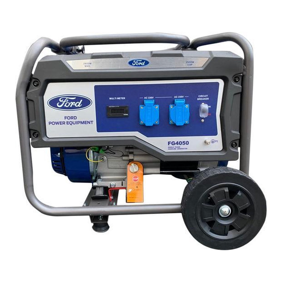
FEATURES FG4050E / FG4650E FG4050 / FG4650 A - ON/OFF Switch D - Sockets 230V E - Circuit Protectors B - VFT Meter (Voltage, Frequency, Time/hours) C - Grounding Stud... - Page 8 FEATURES -UK A - ON/OFF Switch D - Sockets 230V E - Circuit Protectors B - VFT Meter (Voltage, Frequency, Time/hours) P - Voltage Switch C - Grounding Stud...
- Page 9 FEATURES -UK A - ON/OFF Switch D - Sockets 230V E - Circuit Protectors B - VFT Meter (Voltage, Frequency, Time/hours) P - Voltage Switch C - Grounding Stud...
- Page 10 FEATURES-UK A - ON/OFF Switch D - Sockets 230V E - Circuit Protectors B - VFT Meter (Voltage, Frequency, Time/hours) P - Voltage Switch C - Grounding Stud...
- Page 11 FEATURES F - Fuel Gauge K - Fuel Tank G - Generator Frame L - Fuel Fill Cap H - Choke Lever M - Fuel Valve (ON/OFF) N - Recoil Starter Grip I - Air Filter O - Oil Fill (Dipstick) J - Oil Drain Plug...
-
Page 12: Assembly
ASSEMBLY Unpacking 1. Place box on a level surface. 2. Remove all items from box except the generator. Make sure all items listed on the packing list are included and not damaged. 3. Cut down the sides of the box being careful to avoid hitting the generator. Packing List Check all loose parts to the following list. -
Page 13: Attaching Battery Cable
ASSEMBLY Remove Shipping Bracket (See fig 1) • Remove and discard the two RED shipping brackets and mounting hardware before starting the Generator. Fig 1 Attaching Battery Cable (See fig 2) • Parts needed - Black and Red battery cable •... -
Page 14: Adding / Checking Engine Oil
ASSEMBLY Fig 3 Fig 4 Attaching Wheels (See fig 3) • Parts needed - 2 wheels, 2 axles, 2 hair pins, 2 washers, 2 hub caps and 2 self-tapping screws. • Raise or tilt generator so you can slide the wheel axle pin into the wheel, the washer, the wheel mounting hole located on the side of the frame. -
Page 15: Connecting Generator To An Electrical System
ASSEMBLY You must add oil before first operating this generator. Always check oil level before each operation. DO NOT USE E15 OR E85 FUEL IN THIS UNIT. IT IS A VIOLATION OF FEDERAL LAW AND WILL DAMAGE THE UNIT AND VOID YOUR WARRANTY. Fig 5 Fig 6 Connecting Generator to an Electrical System... -
Page 16: How To Start Engine
OPERATION Generator must be properly grounded to prevent electrocution. • Only operate generator on a level surface. • Always connect the nut and ground terminal on the frame to an appropriate ground source. How to Start Engine (See fig 8-12) •... -
Page 17: How To Stop Engine
OPERATION Never start or stop engine with electrical devices plugged in to the receptacles. Failure to WARNING! do so could damage the generator and / or connected electrical devices. • Always start the engine and let it stabilize before connecting any electronic devices. •... - Page 18 OPERATION Handle Pull Plate Turn Around Handle pin Handle pin lock status unlocked Fig 19 Fig 20 Handle operation(see fig 19-22) • Use one hand to pull the handle pin puller, then pull it to a certain resistance while the other hand rotates the handle. (The handle pin is unlocked.) •...
-
Page 19: Receptacles And Extension Cords
OPERATION Receptacles and Extension Cords Only use high quality, well-insulated, grounded extension cords in good condition with generator receptacles. Follow each load manufacturer’s power rating recommendation when selecting receptacle and extension cord. Voltage selector switch---UK This switch allows the generator to operate in either single voltage 115V or dual voltage (115/230V) mode. When placed in the 115V position it allows you to receive the full capacity of the generator by duplex (5-20R) at 115V receptacles. -
Page 20: Don't Overload Generator
OPERATION Don’t Overload Generator Make sure you can supply enough rated watts and surge watts for all electronic devices connected to the generator. Rated watts refer to the power a generator must supply to keep a device running. Surge watts refer to the power a generator must supply to start an electronic device. -
Page 21: Power Management
OPERATION Never exceed generator’s wattage / amperage capacity. This could damage the generator and / or connected electrical devices. Check operating voltage and frequency requirements of all electrical devices prior to plugging them into the generator. • Hour Meter (See Fig 15) The digital hour meter operates whenever the engine is running and keeps track of how many hours the unit has been used. -
Page 22: Maintenance
MAINTENANCE Creating a Temporary Cold Weather Shelter In an emergency, the original shipping carton can be used as a temporary shelter. The shelter should hold enough heat created by the generator to prevent icing. Cut off all flaps. Cut off one of the long sides of the carton to expose the units muffler and exhaust. Do not enclose the muffler / exhaust side of the generator. -
Page 23: Changing Oil
MAINTENANCE Changing Oil (See Fig 16) • Run the Generator until the Engine is warm. • Place generator on a level surface. • Remove the crankcase dipstick. • Place an oil pan underneath the oil drainage bolt to collect used oil. Oil Fill &... - Page 24 MAINTENANCE Used oil should be disposed of at an approved disposal site. See your local oil retailer for more information. Air Filter (See Fig 17) A dirty air filter will reduce the life span of the engine, make it difficult to start the engine, and reduce the unit’s performance. •...
- Page 25 MAINTENANCE Carburetor Adjustment The carburetor is low emission and is equipped with a non-adjustable idle mixture valve. If adjustment is needed contact an authorized dealer. Replacing Fuel Filter (See Fig 20) Occasionally the fuel filter may become clogged and need replacing. To purchase a replacement fuel filter contact the customer service or your local small Engine repair shop.
-
Page 26: Storage And Transportation Of The Generator
MAINTENANCE Draining the carburetor • Turn the engine OFF. • Turn the fuel valve to the OFF position. • Position a suitable container under the carburetor drain screw to catch fuel; loosen the screw. • Allow fuel to drain completely into container. •... -
Page 27: Troubleshooting
TROUBLESHOOTING Problem Cause Solution Engine is running, but AC output is not 1. Open circuit breaker 1. Reset circuit breaker available 2. Poor connection 2. Check and repair 3. Defective cord set 3. Check and repair 4. Connected device is faulty 4. -
Page 28: Diagrams
DIAGRAMS RECOIL START TYPE... - Page 29 DIAGRAMS ELECTRIC START TYPE...
- Page 30 DIAGRAMS UK: FG4050 / FG4650...
- Page 31 DIAGRAMS UK: FG4050E / FG4650E...
- Page 32 DIAGRAMS UK: FG4650...
- Page 33 DIAGRAMS UK: FG4650E...
-
Page 34: Noise
This information, however, will enable the user of the machine to make a better evaluation of the hazard and risk. Measured according with ISO8528-10, ISO 3744 and Noise Directive 2000/14/EC. MODEL FG4050(E) FG4650(E) Emission sound pressure level at the operator’s operation (according with... -
Page 35: Service
SERVISE WARRANTY: Please see the separate sheet in accessories. CE DECLARATION: Please see the separate sheet in accessories. HOW TO CONTACT US: To order parts, receive warranty assistance, or other services inquiries, please see the warranty sheet. Record the following information bellow for service or warranty assistance. Date of Purchase: Model Number: Series Number:...
Need help?
Do you have a question about the FG4050 and is the answer not in the manual?
Questions and answers