Table of Contents
Advertisement
Quick Links
Advertisement
Table of Contents

Related Manuals for ABB REM 543


Summary of Contents for ABB REM 543
- Page 1 REM 543 1 MRS750915-MUM Protection, Monitoring and Issued: 16.10.1998 Version: A Control Checked: T.S. Approved: R.H. Technical Reference Manual Station Automation Part 1, General Data subject to change without notice & Protection ABB Network Partner...
-
Page 2: Table Of Contents
ABB Network Partner REM 543 Protection, Technical Reference Manual Monitoring and Control Part 1, General Introduction ....................5 General ......................5 Hardware versions ..................6 Safety Information ..................7 Instructions ..................... 8 Application ....................8 Requirements ....................9 Configuration ..................... 10 Technical Description .................. - Page 3 Latched alarm, blinking LEDs ............47 Interlocking ..................48 General control test mode ............48 Design description ..................48 Technical data ..................48 Terminal diagram of REM 543 ..............52 Definition of power direction .............53 Terminal connections ................53 Service ......................56 Ordering Information ..................57 Type designations and hardware number ..........57 Hardware versions of REM 543 ..............58...
- Page 4 Part 1, General About this manual This document, Part 1 of the Technical Reference Manual for REM 543, provides a gen- eral technical description of the rotating machine terminal REM 543. For detailed information about the separate protection and other functions listed in sec- tion 4.1.1., refer to the version 2.0 of the CD-ROM “Technical Descriptions of Func-...
-
Page 5: Introduction
The MMI including an LCD display with different views makes the local use of the REM 543 rotating machine terminal safe and easy. The MMI instructs the user how to proceed. -
Page 6: Hardware Versions
ABB Network Partner REM 543 Protection, Technical Reference Manual Monitoring and Control Part 1, General 1.2. Hardware versions The REM 543 rotating machine terminal contains several hardware versions. HW versions REM 543 Analogue interface Sensor channels (current or voltage) Transformers... -
Page 7: Safety Information
ABB Network Partner REM 543 Protection, Technical Reference Manual Monitoring and Control Part 1, General Safety Information Dangerous voltages can occur on the connectors, even though the auxiliary voltage is disconnected. National and local electrical safety regulations must always be followed. -
Page 8: Instructions
Compared to the traditional use of separate products, the combination of libraries pro- vides cost-effective solutions. Application-specific libraries together with the relay con- figuration (IEC 1131 standard) allow the REM 543 protection terminals to be easily adapted to different kinds of applications. -
Page 9: Requirements
3∆I> X<< 3∆I>> remex Fig. 3.1-1. Basic functions of the integrated machine terminal REM 543. 3.2. Requirements If the environmental conditions differ from those specified in section "Technical data", as to temperature and humidity, or if the atmosphere around the machine terminal con- tains chemically active gases or dust, the terminal should be visually inspected in asso- ciation with the secondary testing. -
Page 10: Configuration
3.3. Configuration The REM 543 machine terminals are adapted to specific applications by using the Relay Configuration Tool included in the CAP 505 Tool Box. The tool is used for configuring the basic terminal, protection and logic function blocks, control and measurement func- tions, timers and other functional elements included in a logic functions library (refer to section “Relay configuration”). -
Page 11: Technical Description
4.1.1.2. Protection functions Protection is one of the most important functions of the REM 543 machine terminal. The protection function blocks (e.g. NOC3Low) are independent of each other and have their own setting groups, data recording, etc. As an example, the non-directional over- current protection includes the three stages NOC3Low, NOC3High and NOC3Inst, each with independent protection functions. - Page 12 ABB Network Partner REM 543 Protection, Technical Reference Manual Monitoring and Control Part 1, General The protection functions available for the REM 543 machine terminal: Function Description CUB3Low Phase discontinuity protection DEF2Low Directional earth-fault protection, low-set stage DEF2High Directional earth-fault protection, high-set stage...
-
Page 13: Measurement Functions
VOC6High Voltage-dependent overcurrent protection, high-set stage 4.1.1.3. Measurement functions The measurement function blocks are documented on the CD-ROM “Technical Descriptions of Functions” (1MRS750889-MCD). The measurement functions available for REM 543: Function Description MECU1A Neutral current measurement MECU1B Neutral current measurement... - Page 14 ABB Network Partner REM 543 Protection, Technical Reference Manual Monitoring and Control Part 1, General The control functions available for REM 543: Function Description COCB1 Circuit breaker 1 control with indication COCB2 Circuit breaker 2 control with indication COCBDIR Direct open for CBs via MMI...
-
Page 15: Condition Monitoring Functions
Monitoring and Control Part 1, General 4.1.1.5. Condition monitoring functions The condition monitoring function blocks are documented on the CD-ROM “Technical descriptions of Functions” (1MRS750889-MCD). The condition monitoring functions available for REM 543: Function Description CMBWEAR1 Circuit-breaker electric wear 1 CMBWEAR2... - Page 16 ABB Network Partner REM 543 Protection, Technical Reference Manual Monitoring and Control Part 1, General Function Description Comparison to less / equal LIMIT Limitation Comparison to less Maximum Minimum Multiplication Multiplexer Comparison to greater / less Complement OR connection Selection...
-
Page 17: Communication
The programmable sys- tem of REM 543 machine terminals allows the output contacts to be operated in accord- ance with the state of the logic inputs and the outputs of protection, control, measurement and condition monitoring functions. -
Page 18: Mimic Configuration
ABB Network Partner REM 543 Protection, Technical Reference Manual Monitoring and Control Part 1, General Detailed information about the Relay Configuration Tool is given in the two manuals for the tool (refer to section “References”). 4.1.2.2. MIMIC configuration The MIMIC, a picture on the graphic LCD, is designed with the Relay Mimic Editor. In addition, the editor is used to define the eight programmable LED indicators and the corresponding alarm texts on the front panel, as well as the alarm modes. -
Page 19: Lon Network Configuration
ABB Network Partner REM 543 Protection, Technical Reference Manual Monitoring and Control Part 1, General Interlocking LED texts can also be defined in the same alarm view, but the interlocking LED colours cannot be changed. An interlocking LED has two special modes, the nor- mal state of the LED being inactive. -
Page 20: Rated Frequency
ABB Network Partner REM 543 Protection, Technical Reference Manual Monitoring and Control Part 1, General Comm_In Comm_Out Comm_In Comm_Out Comm_Out Comm_In nv_state nv_state nv_state nv_state nv_state nv_state nv_state nv_state nv_state >1 >1 >1 Blocking Blocking Blocking Open Open Open enable... -
Page 21: External Parameterization
4.1.3.2. External parameterization The Relay Setting Tool is used for parameterizing and setting the REM 543 machine terminals externally. The parameters can be set off-line on a PC and downloaded to the relay over a communication port. The menu structure of the relay setting tool, including views relating to parameterization and settings, is the same as the menu structure of the machine terminal. -
Page 22: Auxiliary Voltage
4.1.4.1. Power supply versions The power supply module PS1/_ is available for the REM 543. The module is available in two versions with identical output voltages but different input voltages. The input voltage range of the power supply module is marked on the front panel of the machine terminal. -
Page 23: Overtemperature Indication
In addition to conventional matching transformers, current sensors and voltage dividers developed by ABB can be used in REM 543 machine terminals. The machine terminal has 8 sensor inputs. A current sensor (Rogowski coil) or a voltage divider can be con- nected to each sensor input. - Page 24 ABB Network Partner REM 543 Protection, Technical Reference Manual Monitoring and Control Part 1, General thermore, the machine terminal has two internal analogue channels, channels 11 and 12, which form the calculated neutral current and residual voltage from phase currents and voltages.
- Page 25 ABB Network Partner REM 543 Protection, Technical Reference Manual Monitoring and Control Part 1, General Measuring units Ch No. Current Voltage Rogovski coil/- Voltage divider Signal type Transformer Transformer sensor (RS) (VD) (selectable (CT) (VT) alternatives) Current Voltage RS type 1, 2, 3...
- Page 26 DIFF DIFF Fig. 4.1.5.-1. Analogue channel configurations of REM 543 products. The hardware versions of REM 543 are the following (for more detailed information refer to section "Hardware versions of REM 543"): • 1MRS090212-AA_/CA_ (5 CTs, 4VTs) • 1MRS090214-AA_/CA_ (6 CTs, 3VTs) •...
-
Page 27: Setting The Rated Current For The Protected Unit
ABB Network Partner REM 543 Protection, Technical Reference Manual Monitoring and Control Part 1, General The last letter of the hardware version number specifies whether the machine terminal is to be equipped with conventional matching transformers or with matching transformers and sensor inputs. -
Page 28: Technical Data Of The Measuring Devices
ABB Network Partner REM 543 Protection, Technical Reference Manual Monitoring and Control Part 1, General 4.1.5.2. Technical data of the measuring devices The technical data of the measuring devices is set in their own dialogue boxes in the Relay Configuration Tool. The set values will affect the measurements carried out by the machine terminal. -
Page 29: Calculated Analogue Channels
4.1.5.3. Calculated analogue channels The REM 543 machine terminal includes two virtual channels to obtain the neutral cur- rent and residual voltage when sensors are used. Current sensors and voltage dividers are directly connected to the machine terminal via coaxial cables and therefore a resid- ual connection of the phase currents or an open-delta connection of the phase voltages cannot be made. -
Page 30: Binary Inputs
Filter time of a binary input The filter time removes debounces and short disturbances on a binary input. The filter time is set for each binary input of the REM 543 machine terminal. The operation of input filtering is illustrated below. -
Page 31: Inversion Of A Binary Input
ABB Network Partner REM 543 Protection, Technical Reference Manual Monitoring and Control Part 1, General Input Filtered Input Filter Time Filter Time dipo Fig. 4.1.6.1.-1. Filtering of a binary input. In the figure above, the input signal is named ’Input’, the filter timer is named ’Filter’... -
Page 32: Pulse Counters
4.1.6.3. Pulse counters Some specific binary inputs (see the table in section “Binary inputs”) of the REM 543 machine terminal can be programmed either as binary inputs or as pulse counters. This programming is done via the parameter Input # mode (in this parameter as well as in others mentioned below, # denotes the input number). -
Page 33: Oscillation Suppression
ABB Network Partner REM 543 Protection, Technical Reference Manual Monitoring and Control Part 1, General 4.1.6.4. Oscillation suppression Oscillation suppression is used to reduce the load from the system when a binary input, for some unrecognized reason, starts oscillating. A binary input is regarded as oscillat- ing if the number of valid status changes (= number of events after filtering) during 1 second is greater than the set value Input osc. -
Page 34: Binary Outputs
The example below shows how the attributes of the binary input 1 (PS1_4_BI1 on PS1 module) of the machine terminal REM 543 are named for the configuration: PS1_4_BI1IV; binary input invalidity PS1_4_BI1;... -
Page 35: High-Speed Double-Pole Power Outputs (Hspo)
ABB Network Partner REM 543 Protection, Technical Reference Manual Monitoring and Control Part 1, General For detailed information about terminal connections for outputs, please refer to terminal diagrams, where all the outputs are included with relay connector terminals. For detailed technical data of the outputs, refer to the section “Technical Data”. -
Page 36: Signalling Outputs (So)
Fig. 4.1.7.2.-1. Signalling output (SO). 4.1.8. Trip circuit supervision The trip circuit supervision inputs TCS1 and TCS2 in the REM 543 machine terminal consist of two functional units: • a constant current generator including the necessary hardware elements • a software-based functional unit for signalling The functional units are based on function blocks included in a condition monitoring library. - Page 37 ABB Network Partner REM 543 Protection, Technical Reference Manual Monitoring and Control Part 1, General Mathematically the operating condition can be expressed as: - (Rh + Rh ) x I > 20 V ac/dc, where (ext.) (int.) • U = operating voltage over the supervised trip circuit •...
-
Page 38: Configuring The Trip Circuit Supervision Cmtcs
The trip circuit supervision inputs in the machine terminal configuration are as follows: TCS1 and TCS2 inputs in REM 543: Trip Circuit Supervision 1 input PS1_4_TCS1 4.4, TCS1... -
Page 39: Self-Supervision (Irf)
Descriptions of Functions for CMTCS1 and CMTCS2 (1MRS750889-MCD). 4.1.9. Self-supervision (IRF) The REM 543 machine terminal is provided with an extensive self-supervision system. The self-supervision system handles run-time fault situations and informs the user of faults via the MMI and LON/SPA communication. -
Page 40: Fault Codes
4.1.9.1. Fault codes When an internal fault is detected in a REM 543 machine terminal, the fault code is recorded and can be read from the main menu Relay Status/General/IRF code. The IRF code shows the first internal fault detected by the self-supervision system. This fault code should be recorded and stated when overhaul is ordered. -
Page 41: Lon/Spa Bus Communication On The Rear Connector X3.3
RS-485 (connector X3.3) is selected with the “Protocol 3” setting parameter in the menu Communic. lib./General. The other communication parameters for the rear RS-485 interface are also set in the Communication menu of the REM 543 machine terminal. -
Page 42: System Structure
SPACOM units or other SPA bus devices (devices connected to the system via the SPA bus). LON devices made by other manufacturers or other ABB companies may be used for various BI, AI and BO functions. MicroSCADA is used for local control. -
Page 43: Lon Inputs And Outputs Via A Lon Bus
4.1.10.5. LON inputs and outputs via a LON bus The REM 543 machine terminal offers up to 32 freely programmable LON inputs and outputs on the LON bus. The inputs and outputs use the LONMARK Standard network variable (NV type 83 = SNVT_state) for sending and receiving process data. The LON... -
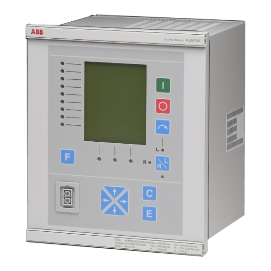
Page 44: Display Panel (Mmi)
4.1.11. Display panel (MMI) The front panel of the REM 543 machine terminal includes: • a graphic LCD display, with the resolution 128 x 160, consisting of 19 rows divided into two windows: a main window (17 rows) and an assisting window (2 rows) •... -
Page 45: Alarm Indication Leds
4.1.12. Alarm indication LEDs The REM 543 machine terminal offers eight alarm indication LEDs to be freely config- ured with the Relay Mimic Editor. ON and OFF state texts (max. 16 characters) and LED colours (green, yellow or red) can be freely defined. Three basic operation modes are supported: •... -
Page 46: Non-Latched Alarm
ABB Network Partner REM 543 Protection, Technical Reference Manual Monitoring and Control Part 1, General Alarm channels are seen as function blocks in the machine terminal configuration: Alarm channel Function block Alarm channel 1 MMIALARM1 Alarm channel 2 MMIALARM2 Alarm channel 3... -
Page 47: Latched Alarm, Steady Led
ABB Network Partner REM 543 Protection, Technical Reference Manual Monitoring and Control Part 1, General 4.1.12.2. Latched alarm, steady LED Latched, steady alarms can be acknowledged only when the ON signal is inactive. The time stamp of the first alarm is recorded. Successful acknowledgement clears the time stamp line of the alarm view and the corresponding alarm LED. -
Page 48: Interlocking
ABB Network Partner REM 543 Protection, Technical Reference Manual Monitoring and Control Part 1, General Latched, blinking (example 2) ALARM Off text On text On text Off text Off colour for steady LED 09-24 12:40:00 On color for steady led... - Page 49 ABB Network Partner REM 543 Protection, Technical Reference Manual Monitoring and Control Part 1, General Table 2: Auxiliary power supplies Type PS1/240V PS1/48V Input voltage, ac 110/120/220/240 V Input voltage, dc 110/125/220 V 24/48/60 V Operating range ac 85…110%, dc 80…120% of dc 80…120% of rated value...
- Page 50 ABB Network Partner REM 543 Protection, Technical Reference Manual Monitoring and Control Part 1, General Dry cold test according to IEC 68-2-1 (BS 2011: Part 2.1 A) Damp heat test cyclic according to IEC 68-2-30 (BS 2011: Part 2.1 Db), r.h.
- Page 51 ABB Network Partner REM 543 Protection, Technical Reference Manual Monitoring and Control Part 1, General Table 9: Data communication Rear interface, connector X3.3 RS485 connection LON bus or SPA bus, selectable the fibre-optic interface module RER 103 is needed for galvanic...
-
Page 52: Terminal Diagram Of Rem 543
ABB Network Partner REM 543 Protection, Technical Reference Manual Monitoring and Control Part 1, General 4.2.2. Terminal diagram of REM 543 X4.1 X1.1 PS1_4_ACFail Mains Ch 10, VT4 100V PS1_4_TempAlarm Ch 9, VT3 100V X3.3 SERIAL BUS 100V Ch 8, VT2 X4.1... -
Page 53: Definition Of Power Direction
2.5 mm wires. ABB sensors (Rogowski coil or voltage divider) are connected to the connectors X2.1...X2.8. A special type shielded twin BNC connector (e.g. type AMP 332225 or Amphenol 31-224) is used to improve reliability and protection against disturbances. - Page 54 IRF is linked to the terminals X4.1:3, X4.1:4 and X4.5:3. Protective earth is connected to the screw marked with the earth symbol. The connectors are designated according to the module slot in the REM 543 machine terminal. Connector Description X1.1...
- Page 55 ABB Network Partner REM 543 Protection, Technical Reference Manual Monitoring and Control Part 1, General X7.1 X6.1 X5.1 X4.1 X1.1 X2.1 X3.1 X2.2 X2.3 X3.2 X2.4 X3.3 X7.2 X6.2 X5.2 X4.2 X2.5 X2.6 X2.7 X2.8 rem543s Fig. 4.2.3.-1. Rear view of REM543 (1MRS090212-AAB/CAB).
-
Page 56: Service
Please contact the manufacturer or his nearest representative for further information about checking, overhaul and recalibration of the terminal. Note! To achieve the best possible operation accuracy, all parts of a REM 543 product have been calibrated together. Thus, each product forms a whole for which no separate spare parts can be supplied. -
Page 57: Ordering Information
Monitoring and Control Part 1, General Ordering Information Ordering information for REM 543 machine terminals includes a hardware number and several software order numbers. The hardware number indentifies the hardware version. The application numbers specify the functions included. The hardware number and a combined software number is labelled on the marking strip on the front panel of the machine terminal delivered. -
Page 58: Hardware Versions Of Rem 543
6.2. Hardware versions of REM 543 All the REM 543 machine terminal hardware versions include the same number of binary inputs and outputs. The number of matching transformer and sensor inputs and the auxiliary voltage range vary between the different hardware versions. -
Page 59: Software Configuration
6.3. Software configuration Each REM 543 machine terminal allows different software configurations that are based on application-specific libraries. When selecting the right software configuration, the following items should be determined: • protection functions to be incorporated in the machine terminal •... -
Page 60: References
ABB Network Partner REM 543 Protection, Technical Reference Manual Monitoring and Control Part 1, General References Other manuals for REM 543 • Installation Manual 1MRS 750526-MUM • Operator’s Manual 1MRS 750500-MUM • Technical Descriptions of Functions 1MRS 750889-MCD • Configuration Guideline... -
Page 61: Glossary
ABB SPACOM ABB product family trip circuit supervision voltage transformer *) LON is a trademark of Echelon Corporation registered in the United States and other countries. - Page 62 ABB Network Partner REM 543 Protection, Technical Reference Manual Monitoring and Control Part 1, General Page 62...
-
Page 63: Customer Feedback
ABB Network Partner REM 543 Protection, Technical Reference Manual Monitoring and Control Part 1, General Customer Feedback Date: To fax: +358 10 224 1094 ______________________________________________________________________ Description: Category: _ Comment _ Query _ Complaint In case of feedback related to a specific product, please name the product. - Page 64 ABB Network Partner REM 543 Protection, Technical Reference Manual Monitoring and Control Part 1, General Service Report for REM 543 Name of the station/project ___________________________________________________ (Fill in this form. Use one form per relay.) Date & Time_______________________ Relay information (from the...
- Page 65 ABB Network Partner REM 543 Protection, Technical Reference Manual Monitoring and Control Part 1, General Page 65...
- Page 66 ABB Network Partner REM 543 Protection, Technical Reference Manual Monitoring and Control Part 1, General Page 66...
- Page 67 ABB Network Partner REM 543 Protection, Technical Reference Manual Monitoring and Control Part 1, General Page 67...
- Page 68 ABB Transmit Oy Relays and Network Control P.O. Box 699 FIN-65101 Vaasa Finland Telephone: +358-10 22 4000 Fax: +358-10 224 1094...