Table of Contents
Advertisement
Quick Links
Advertisement
Table of Contents
Troubleshooting

Related Manuals for Mindray iPM-9800


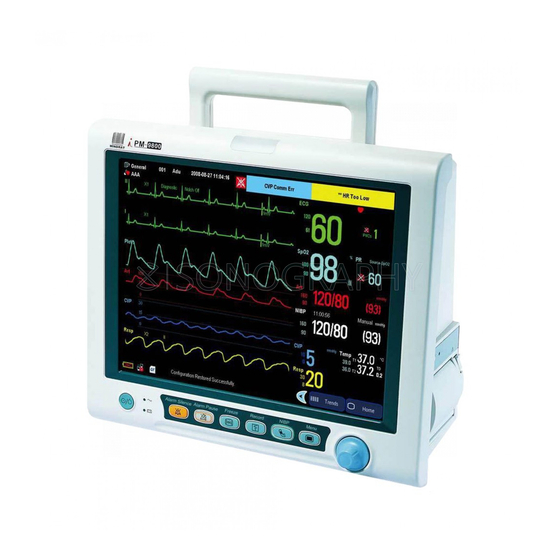
Summary of Contents for Mindray iPM-9800
- Page 1 Patient Monitor Service Manual...
- Page 3 This manual has a revision number. This revision number changes whenever the manual is updated due to software or technical specification change. Contents of this manual are subject to change without prior notice. Revision number: 1.0 Release time: January 2009 © 2009 Shenzhen Mindray Bio-Medical Electronics Co., Ltd. All rights reserved.
- Page 4 Mindray, nor the rights of others. Mindray intends to maintain the contents of this manual as confidential information. Disclosure of the information in this manual in any manner whatsoever without the written permission of Mindray is strictly forbidden.
- Page 5 Preface Manual Purpose This manual provides detailed information about the assembling, dissembling, testing and troubleshooting of the equipment to support effective troubleshooting and repair. It is not intended to be a comprehensive, in-depth explanation of the product architecture or technical implementation. Observance of the manual is a prerequisite for proper equipment maintenance and prevents equipment damage and personnel injury.
- Page 6 315666 For accessing the [User Maintenance] menu, there is also a super password which will not be changed. The super password is MINDRAY You may need a password to enter the [Archives] menu, depending on the [Archives Access] setting in configuration mode. The password is the same as the one for accessing...
-
Page 7: Table Of Contents
Contents 1 Safety..........................1-1 1.1 Safety Information ......................1-1 1.1.1 DANGER ......................1-2 1.1.2 Warnings ......................1-2 1.1.3 Cautions ......................1-2 1.1.4 Notes ........................1-3 1.2 Equipment Symbols ......................1-3 2 Theory of Operation ......................2-1 2.1 Introduction........................2-1 2.2 System Connections......................2-2 2.2.1 Mounting the Patient Monitor ................ - Page 8 3.4.3 ECG Tests......................3-7 3.4.4 Resp Performance Test..................3-8 3.4.5 NIBP Tests......................3-9 3.4.6 IBP Tests ......................3-12 3.4.7 SpO Test......................3-14 3.4.8 C.O. Test......................3-14 3.4.9 Temp Test ......................3-14 3.4.10 AG Tests ......................3-15 3.5 Nurse Call Relay Performance Test ................3-18 3.6 Analog Output Performance Test ..................
- Page 9 5 Repair and Disassembly ....................5-1 5.1 Tools..........................5-1 5.2 Preparations for Disassembly..................5-1 5.3 Separating the Front and Rear Half of the Monitor............5-2 5.4 Disassembling the Front Housing Assembly ..............5-3 5.4.1 Removing the Main Board ................. 5-3 5.4.2 Disconnecting the Knob Encoder...............
- Page 10 6.4.10 Fan Assembly ....................6-22 6.4.11 Li-ion Battery Interface Board Assembly............6-23 6.4.12 Lead-acid Battery Interface Board Assembly ..........6-24 6.4.13 Mindray Sidestream CO2 Module ..............6-25 6.4.14 Oridion Microstream CO2 Module ..............6-26 6.4.15 Mainstream CO2 Module................6-27 6.4.16 Others ......................6-28 6.5 Replaceable Parts ......................
-
Page 11: Safety
Safety 1.1 Safety Information DANGER Indicates an imminent hazard that, if not avoided, will result in death or serious injury. WARNING Indicates a potential hazard or unsafe practice that, if not avoided, could result in death or serious injury. CAUTION Indicates a potential hazard or unsafe practice that, if not avoided, could result in minor personal injury or product/property damage. -
Page 12: Danger
1.1.2 Warnings WARNING All installation operations, expansions, changes, modifications and repairs of this product are conducted by Mindray authorized personnel. There is high voltage inside the equipment. Never disassemble the equipment before it is disconnected from the AC power source. -
Page 13: Notes
1.1.4 Notes NOTE Refer to Operator’s Manual for detailed operation and other information. 1.2 Equipment Symbols Some symbols may not appear on your equipment. Attention: Consult accompanying documents (this manual). Power ON/OFF (for a part Battery indicator of the equipment) Alternating current (AC) Alarm silenced. - Page 14 The following definition of the WEEE label applies to EU member states only. This symbol indicates that this product should not be treated as household waste. By ensuring that this product is disposed of correctly, you will help prevent bringing potential negative consequences to the environment and human health. For more detailed information with regard to returning and recycling this product, please consult the distributor from whom you purchased it.
-
Page 15: Theory Of Operation
Theory of Operation 2.1 Introduction This patient monitor is intended to be used for monitoring, displaying, reviewing, storing and transferring of multiple physiological parameters including ECG, respiration (Resp), temperature (Temp), SpO , pulse rate (PR), non-invasive blood pressure (NIBP), invasive blood pressure (IBP), cardiac output (C.O.), End tidal CO value (EtCO ) and anesthetic gas... -
Page 16: System Connections
2.2 System Connections 2.2.1 Mounting the Patient Monitor The patient monitor can be mounted on a wall bracket or on a trolley support. The wall bracket or trolley support can be ordered optionally. Each type of mounting bracket is delivered with a complete set of mounting hardware and instructions. Refer to the documentation delivered with the mounting hardware for instructions on assembling mounts. -
Page 17: Connectors For Peripheral Devices
2.2.2 Connectors for Peripheral Devices On the back of the patient monitor you will find all connectors for peripheral devices. Network Connector: It is a RJ45 connector used to connect an ethernet network or a Video Connector: It connects a standard VGA color monitor, which extends the display capability of the monitor. -
Page 18: Main Unit
2.3 Main Unit The following diagram illustrates the structure of the patient monitor. The functional modules/parts of the main unit are described in the following sections. 2.3.1 Power board (AC/DC) The power board switches AC power to DC power as the output. 2.3.2 Battery interface board The battery interface board introduces battery power to the internal system. -
Page 19: Power Management And Interface Board
2.3.3 Power management and interface board This board is responsible for power management and interfaces. Power management can perform the functions below: 1. Outputting 12V, 5V, and 3.3V DC power 2. Power On/Off control 3. Charge/Discharge control The interface part has a USB HUB and supports two USB ports, networks, RS232, and such signal output as VGA signals and analog signals. -
Page 20: Multi-Parameter Board
The Multi-parameter board measures the respiration rate of patients using the impedance method, and can monitor the respiration rate with two ECG leads. The Multi-parameter board is integrated with Mindray SpO2 circuit. If a monitor is configured with an OEM SpO2 module, the function of Mindray SpO2 is shielded. -
Page 21: Ag Module
2.3.14 AG module The AG module of ARTEMA can analyze multiple gases with the sidestream technology and is intended for anesthesia and intensive care. The infrared sensor of the module can measure 8 infrared lights of varied wavelength. The concentration of multiple gases can be calculated precisely through the nonlinear matrix algorithm. - Page 22 FOR YOUR NOTES...
-
Page 23: Testing And Maintenance
Testing and Maintenance 3.1 Introduction To ensure the patient monitor always functions normally, qualified service personnel should perform regular inspection, maintenance and test. This chapter provides a checklist of the testing procedures for the patient monitor with recommended test equipment and frequency. The service personnel should perform the testing and maintenance procedures as required and use appropriate test equipment. -
Page 24: Test Report
3.1.1 Test Report After completing the tests, service personnel are required to record test results in this table and report them to Mindray Customer Service Department. Test Equipment Name Model/PN Expiry Date Test Record Test Item Test Site Test Results... -
Page 25: Recommended Frequency
3.1.2 Recommended Frequency Check/Maintenance Item Frequency Visual test 1. When first installed or reinstalled. Power on test 1. When first installed or reinstalled. 2. Following any maintenance or the replacement of any main unit parts. Mainstream 1. If user suspects that the measurement is incorrect. test 2. -
Page 26: Visual Test
2. At least once every two years. Earth leakage current test Patient leakage current test Patient auxiliary current test Touchscreen 1. When the touchscreen appears abnormal. calibration 2. After the touchscreen is replaced. Recorder check Following any repair or replacement of the recorder. 3.2 Visual Test Inspect the equipment for obvious signs of damage. -
Page 27: Power On Test
3.3 Power On Test This test is to verify that the patient monitor can power up correctly. The test is passed if the patient monitor starts up by following this procedure: Insert two batteries in the battery chamber and connect the patient monitor to the AC mains. -
Page 28: Sidestream And Microstream Co Module Test
3.4.2 Sidestream and Microstream CO Module Test Leakage test Follow this procedure to perform the test: Enter the [CO2 Setup] menu to set [Operating Mode] to [Measure]. Wait for CO module warmup. Block the gas inlet completely. Sidestream: Check that alarm message [CO2 FilterLine Err] is displayed on the screen in 3s. -
Page 29: Ecg Tests
Connect the gas bottle with the tubing using a T-shape connector as shown below. Check the airway and make sure there are no leaks. Open to the air Tubing Gas valve Monitor Gas bottle Open the gas valve and vent CO2 into the tubing. In the [Calibrate CO2] menu, enter the vented CO concentration in the [CO2] field. -
Page 30: Resp Performance Test
ECG Calibration The ECG signal may be inaccurate due to hardware or software problems. As a result, the ECG wave amplitude becomes greater or smaller. In that case, you need to calibrate the ECG module. In the main menu, select [Maintenance >>]→[User Maintenance >>]→enter the required password and then select [Calibrate ECG] from the popup menu. -
Page 31: Nibp Tests
3.4.5 NIBP Tests NIBP Accuracy Test Tools required: T-shape connector Appropriate tubing Balloon pump Metal Vessel (volume 500±25 ml) Reference manometer (calibrated with accuracy higher than 1 mmHg) Manometer Monitor Tubing Connector for NIBP cuff Balloon pump Metal vessel Follow this procedure to perform the accuracy test: Connect the equipment as shown above. - Page 32 NIBP Leakage Test Tools required: An adult cuff An air tubing A correct sized cylinder Follow this procedure to perform the leakage test: Set the patient category to [Adu]. Connect the cuff to the NIBP connector on the monitor. Wrap the cuff around the cylinder as shown below. In the main menu, select [Maintenance >>]→[User Maintenance >>]→enter the required password and then select [Maintain NIBP]→[NIBP Leakage Test].
- Page 33 NIBP Calibration Tools required: T-shape connector Appropriate tubing Balloon pump Metal Vessel (volume 500±25 ml) Reference manometer (calibrated with accuracy higher than 1 mmHg) Monitor Manometer Connector for Tubing NIBP cuff Balloon pump Metal vessel Connect the equipment as shown above. Before inflation, the reading of the manometer should be 0.
-
Page 34: Ibp Tests
3.4.6 IBP Tests IBP Performance Test Tool required: Patient simulator Connect the patient simulator to the pressure connector on the monitor. Set the pressure value of patient simulator to 0. In the setup menu for the pressure (e.g. Art), select [Art Zero >>]→[Zero] to start a zero calibration. - Page 35 IBP Pressure Calibration Tools required: Standard sphygmomanometer Balloon pump Tubing T-shape connector Connect the equipment as shown below Pressure transducer 3-way stopcock Pressure adapter cable T-shape connector Monitor Manometer Zero the transducer. After a successful zero, open the stopcock to the manometer. In the main menu, select [Maintenance >>]→[User Maintenance >>]→enter the required password.
-
Page 36: Spo Test
SpO 96%; PR 80 bpm. The displayed SpO and PR values should be within the ranges listed below. PR (bpm) Mindray 96% ± 2% 80 ± 3 Masimo 96% ± 2% 80 ± 3 MAX-A, MAX-AL, MAX-N, MAX-P, 96% ±... -
Page 37: Ag Tests
3.4.10 AG Tests AG Performance Test Tool required: Gas bottle with a certain standard anesthetic gas. Gas concentration should meet AA>1.5%, of which AA represents an anesthetic agent T-shape connector Tubing Enter [Gas Setup] menu and set [Operating Mode] to [Measure]. After the AG module warmup is ready, block the gas inlet of the AG module. - Page 38 Performance Test Tool required: Gas bottle with 100% O T-shape connector Tubing The AG module can incorporate the features of the O module. Refer to AG Performance Test above for test procedures. AG Calibration Tools required: Gas bottle, with a certain standard gas or mixture gas. Gas concentration should meet the following requirements: AA>1.5%, CO >1.5%, N O>40%, O...
- Page 39 Connect the gas bottle, reservoir bag and the tubing using a T-shape connector as shown in the figure below. Check the airway and make sure there are no leaks. Gas valve AG module Tubing Reservoir bag Gas bottle Open the gas valve and vent a certain standard gas or mixture gas into the tubing. In the [Calibrate AG] menu, the concentration and flowrate of each measured gas are displayed.
-
Page 40: Nurse Call Relay Performance Test
3.5 Nurse Call Relay Performance Test Tools required: Multimeter Connect the nurse call cable to the Auxiliary Output Connector of the patient monitor. In the main menu, Select [Maintenance >>]→[User Maintenance >>]→enter the required password. Select [Device Setup >>] to access the [Device Setup] menu. Select [Auxiliary Output] and then [Nurse Call]. -
Page 41: Electrical Safety Tests
3.7 Electrical Safety Tests WARNING Electrical safety tests are a proven means of verifying the electrical safety of the patient monitor. They are intended for determining potential electrical hazards. Failure to find out these hazards timely may cause personnel injury. Commercially available test equipment such as safety analyzer, etc. -
Page 42: Enclosure Leakage Current Test
Tools required: Safety analyzer Isolation transformer 3.7.1 Enclosure Leakage Current Test Connect the 601 safety analyzer to an AC power supply (264 V, 60 Hz). Connect SUM terminal of the applied part connection apparatus to RA input terminal of 601 safety analyzer, another terminal to the applied part of EUT. Connect the EUT to the analyzer’s auxiliary output connector using a power cord. -
Page 43: Patient Leakage Current Test
3.7.3 Patient Leakage Current Test Connect the 601 safety analyzer to an AC power supply (264 V, 60 Hz). Connect SUM terminal of the applied part connection apparatus to RA input terminal of 601 safety analyzer, another terminal to the applied part of EUT. Connect the EUT to the analyzer’s auxiliary output connector using a power cord. -
Page 44: Touchscreen Calibration
3.8 Touchscreen Calibration In the main menu, select [Maintenance >>]→[User Maintenance >>]→enter the required password and then select [Cal. Touchscreen] from the popup menu. will, in turn, appear at different positions of the screen. Select each as it appears on the screen. After the calibration is completed, the message [Screen Calibration Completed!] is displayed. -
Page 45: Factory Maintenance
3.10 Factory Maintenance 3.10.1 Accessing Factory Maintenance Menu To access the factory maintenance menu, in the main menu, select [Maintenance >>] →[Factory Maintenance >>]and then enter the required password. The [Factory Maintenance] menu is shown below. 3.10.2 Setting Trends Length To set the storage time of trends data, select [Trends Length] and toggle between [96] and [192]. -
Page 46: Software Version
3.10.4 Software Version Selecting [Software Version >>] will show software version information. The display of [Software Version] menu is as follows: 3.10.5 Monitor Information Selecting [Monitor Information >>] will show the status of the patient monitor. Monitor information is displayed as follows: 3-24... -
Page 47: Device Configuration
3.10.6 Device Configuration Selecting [Device Config >>] enables you to select modules the device is configured. The display of [Device Config] menu is as follows. 3.10.7 Wireless AP Configuration Selecting [Wireless AP Config >>] enables you to configure the wireless AP by using a PC. 3-25... -
Page 48: Program Upgrade
After upgrading the boot program, re-upgrade the system program and other programs to ensure compatibility. Make sure the version of the upgrade package is you desired one. If you want to obtain the latest upgrade package, contact Mindray Customer Service Department. 3-26... -
Page 49: Troubleshooting
Troubleshooting 4.1 Introduction In this chapter, patient monitor problems are listed along with possible causes and recommended corrective actions. Refer to the tables to check the patient monitor, identify and eliminate the troubles. The troubles we list here are frequently arisen difficulties and the actions we recommend can correct most problems, but not all of them. -
Page 50: Software Version Check
4.4 Software Version Check Some troubleshooting tasks may require you to identify the configuration and software version of your patient monitor. To view information on the system configuration and system software version, in the main menu, select [Maintenance >>]→[Software Version >>]. You can also view the information on system software version and module software version by selecting [Maintenance >>]→[Factory Maintenance >>]→... -
Page 51: Display Failures
4.6.2 Display Failures Symptoms Possible Cause Corrective Action Integrated Cables defective or 1. Check that cables from the display to the main display is blank poorly connected. board and from the backlight board to the main board but the patient are correctly connected. -
Page 52: Alarm Problems
Touch position Touchscreen not Calibrate the touchscreen. invalid calibrated 4.6.3 Alarm Problems Symptoms Possible Cause Corrective Action The alarm lamp is Cable defective or 1. Check that cables from alarm LED board to main not light or poorly connected board are properly connected. extinguished but 2. -
Page 53: Key And Knob Failures
4.6.4 Key and Knob Failures Symptoms Possible Cause Corrective Action Keys do not work Cable defective or 1. Check that cable between key board and main poorly connected board is properly connected. 2. Check that connecting cables and connectors are not damaged. -
Page 54: Interface Failures
4.6.6 Interface Failures Symptoms Possible Cause Corrective Action No analog signals or Respective output 1. In the main menu, select [Others >>]→ nurse call signals are disabled [Analog Output Setup >>]→set [Analog issued Out.] to [On]→select [Waveform] and then select a waveform you want to output. 2. -
Page 55: Cf Card Problems
4.6.7 CF Card Problems Symptoms Possible Cause Corrective Action CF card malfunctions Wrong CF card or small Use only SanDisk-manufactured CF storage memory space cards. Those with 2GB memory space are recommended. CF card failure Replace the CF card. Cable defective or 1. - Page 56 Cable defective or 1. Check that the cable from battery interface poorly connected board to power management and interface board is correctly connected. 2. Check that cables and connectors are not damaged. Power management and Replace the power management and interface board failure interface board.
-
Page 57: Network Related Problems
4.6.9 Network Related Problems Symptoms Possible Cause Corrective Action Frequent dropouts and Incorrect LAN cable Check LAN cable connection. LAN cable network disconnects connection shall not be longer than 50 m. Incorrect IP address Check for IP address conflict. Reconfigure configuration IP address. -
Page 58: Software Upgrade Problems
4.6.10 Software Upgrade Problems Symptoms Possible Cause Corrective Action Boot file upgrade fails Power failure or Return the main board to factory for repair. unintended power off during boot file upgrade Program upgrade fails Incorrect network 1. Check that network connector on the connection patient monitor is used. -
Page 59: Repair And Disassembly
Repair and Disassembly 5.1 Tools During disassembly and replacing, the following tools may be required: Phillips screwdrivers Small flat-bladed screwdrivers (101 or 102) Tweezers Sharp nose pliers Sleeve (M5.5) Electric soldering iron 5.2 Preparations for Disassembly Before disassembling the monitor, finish the following preparations: Stop monitoring the patient, turn off the monitor and disconnect all the accessories and peripheral devices. -
Page 60: Separating The Front And Rear Half Of The Monitor
5.3 Separating the Front and Rear Half of the Monitor Place the monitor in an upright position and unscrew the four M3×10 screws. Pull out the front housing gently. Disconnect the cable connecting the power management and interface board and the main board. Then the front and rear housing can be separated. -
Page 61: Disassembling The Front Housing Assembly
5.4 Disassembling the Front Housing Assembly 5.4.1 Removing the Main Board Place the front housing on a flat surface as shown below and be sure not to damage the knob. Knob 2. Pull out all the connectors on the main board. There are numbers beside the connectors, which are listed below. -
Page 62: Disconnecting The Knob Encoder
Unscrew the five M3×6 screws and take out the main board. There is a battery on the main board. Battery 5.4.2 Disconnecting the Knob Encoder Push out the knob with a small flat-bladed screwdriver from the two holes indicated in the figure below. -
Page 63: Removing The Alarm Led Board
5.4.4 Removing the Alarm LED Board Unscrew the two PT2×8 screws and take out the alarm LED board. Please notice that the alarm LED cable is welded on the alarm LED board. 5.4.5 Removing the LCD Assembly CAUTION Do not touch the LCD screen. Disassemble the LCD screen in an environment as dust-free as possible. - Page 64 To take out the double inverters (if installed), pull out all the connectors on the inverters. Then unscrew the four M2×6 screws. NOTE Pull the connector and avoid damaging the cable when removing the cable connecting the inverter to the LCD screen. When reassembling, make sure you put the insulating cover in place.
- Page 65 Unscrew the eight M3×6 screws and take the screen assembly out carefully. Prevent the screen from being contaminated by dust. Touchscreen...
- Page 66 Unscrew the four M3×8 screws and take the screen out carefully. Prevent the screen from being contaminated or damaged. Clean the screen when reassembling. NOTE When reassembling the front housing assembly, make sure you connect all the cables in place. All the cables must be placed as shown below and fixed in the positioning buckle.
-
Page 67: Disassembling The Rear Housing Assembly
5.5 Disassembling the Rear Housing Assembly 5.5.1 Removing the Recorder Open the recorder door and unscrew the two M3×6 screws. Pull the two clips in the directions as indicated and meanwhile pull out the recorder. Take out the recorder after unplugging the recorder cable. NOTE Be sure not to damage the connecting cables or connectors when pulling out the recorder. - Page 68 5.5.2 Removing the CF/Wireless AP Assembly, CF Assembly or CF slot blank cover To take out the CF/Wireless AP assembly (if installed), unplug their cables from the power management and interface board. Then unscrew the two M3×6 screws. To take out the CF assembly (if installed), unplug the cable from the power management and interface board.
-
Page 69: Removing Co2/Ag Assembly
Unscrew the two M3×6 screws to take out the CF board. Unscrew the M3 nut with a sleeve and remove the screw on the other side. Then take out the wireless AP. The Screw 5.5.3 Removing CO2/AG Assembly To remove the mainstream CO2 assembly: Release the four clips in the directions as indicated with a sharp nose plier. - Page 70 Unplug the communication cable from the multi-parameter board and the mainstream CO2 interface cable. Take out the CO2 interface panel. Then unscrew the two nuts and pull out the mainstream CO2 assembly. NOTE When reinstalling the mainstream CO2 assembly, make sure you place the CO2 interface panel in the proper direction as shown below.
- Page 71 Take out the watertrap assembly and move it through the fixer in the way as shown below. Unplug the communication cable from the multi-parameter board. Unplug the tubing from the gas nipple. Then unscrew the two nuts and pull out the Mindray CO2 assembly. 5-13...
- Page 72 NOTE You can cut part of the tubing if it is hard to be removed from the gas nipple. Avoid damaging the tubing when taking out the watertrap assembly. When reinstalling, fix the tubings with plastic clamp and do not fold the tubings. To remove microstream CO2 assembly: Release the plastic clamp and take out the tubings.
- Page 73 Unplug the communication cable from the multi-parameter board. Unplug the tubing from the gas nipple. Then unscrew the two nuts and pull out the microstream CO2 assembly. NOTE Avoid damaging the tubing and cable when taking out the microstream CO2 interface assembly.
-
Page 74: Removing The Multi-Parameter Board Assembly
Unplug the cable from the multi-parameter board. Unplug the tubing from the gas nipple. Then unscrew the three nuts and one screw and pull out the AG assembly. NOTE You can cut part of the tubing if it is hard to be removed from the gas nipple. Avoid damaging the tubing and cable when taking out the watertrap assembly. -
Page 75: Removing The Main Support Assembly
5.5.5 Removing the Main Support Assembly Take out the cord clamp and then place the rear housing on a flat surface. Unscrew the five M3×6 screws. Unscrew the four M4×8 screws at the bottom and then pull up the main support assembly. -
Page 76: Further Disassembly
5.6 Further Disassembly 5.6.1 Disassembling the Parameter Front Panel Assembly To remove the parameter front panel assembly: Unplug the C.O. cable and IBP3/IBP4 cable from the C.O./IBP module. Unplug the OEM SPO2 cable. Unplug the tubing from the NIBP connector. Unscrew the three M3×6 screws to take out the front panel assembly. - Page 77 To remove the NIBP connector: Unscrew the connector with a sharp nose plier. Then carefully take out the outer part. Do not lose the steel balls. Take out the plastic cover from the outer part with a tweezer. NOTE When reinstalling, insert a magnetic phillips screwdriver into the inner part. Place the four steel balls into the holes and then install the plastic cover.
- Page 78 To remove the cable: Use a sharp nose plier to spin the cable root clockwise until the ribs are exposed. Then pull out the cable. NOTE When reinstalling, insert and spin the cable root to the proper position as shown below.
-
Page 79: Removing The Ibp/C.o. Module
5.6.2 Removing the IBP/C.O. Module Unplug the communication cable to the multi-parameter board. Then unscrew the M3×6 screw to take out the IBP/C.O. module. Screw IBP/C.O. communication cable NOTE When reinstalling, place the board according to the positioning nubs. When reinstalling, do not mix up the IBP3 and IBP4 connectors. Place the cables in the way as shown below. -
Page 80: Removing The Oem Spo2 Module
5.6.3 Removing the OEM SPO2 Module Unplug the communication cable to the multi-parameter board. Unscrew the M3×6 screw to take out the OEM SPO2 module. Screw OEM SPO2 communication cable NOTE When reinstalling, place the board according to the positioning nubs. Positioning nubs 5-22... -
Page 81: Removing The Multi-Parameter Board
5.6.4 Removing the Multi-parameter Board Release the two clamps. Unplug the fast-release valve cable, slow-release valve cable and pump cable. Unplug the tubings. Unscrew the three M3×6 screws and pull up the multi-parameter board. 5-23... - Page 82 Unscrew the two M3×6 screws to take out the ECG shield. NOTE Release the clamps before unplugging the cables. Make sure all the connectors have been removed before taking out the multi-parameter board. Take out the board carefully to avoid damage. When reinstalling the ECG shield, place it according to the positioning slot to avoid the short circuit between the shield and other components.
-
Page 83: Removing The Pump/Valve Assembly
5.6.5 Removing the Pump/Valve Assembly Unplug the tubing from the multiple connected body to pump. Cut the two 4×200mm cable ties. Then take out the pump. Unplug the tubings from the multiple connected body to NIBP connector, pump and pressure sensor on the multi-parameter board. Unscrew the three M2×6 screws to take out the multiple connected body together with the valve. -
Page 84: Disassembling The Main Support Assembly
NOTE When reinstalling the pump, aim the notch of the pump toward the positioning nub on the support rack. When reinstalling the valves, do not mix up the installing positions of the slow-release valve and fast-release valve. When reinstalling, connect all the tubings in position. Notch Positioning nub 5.6.6 Disassembling the Main Support Assembly... - Page 85 Unplug the fan and speaker cables. Unscrew the three M3×6 screws to take out the power management and interface board. Remove the power connector and unscrew the four M3×6 screws to take out the power board. Cut the three 3×80mm cable ties and unscrew the two M3×6 screws to take out the fan assembly.
- Page 86 NOTE When reinstalling the fan, install it in the proper direction. The side with cushion is the air outlet side. When reinstalling, tie the cables in the way as shown above. Unscrew the two M4×10 screws to take out the two battery latches and two latch sleeves.
- Page 87 To remove the battery back board assembly: Unscrew the two M3×6 crosshead screws to take out the lead-acid battery back board (if installed). Unscrew the four M3 nuts to take out the Li-ion battery back board (if installed). NOTE When removing the Li-ion back board, do not unscrew the wrong nuts. Unscrew the six FT3×8 screws to take out the batteries separator.
-
Page 88: Disassembling The Interface Board Assembly
NOTE When reinstalling the batteries separator, aim the notch toward the error-proof pillar. 5.6.7 Disassembling the Interface Board Assembly Unscrew the two M3 nuts to take out the interface board outer support rack. Take out the beryllium copper leaf and unscrew the four stud screws and one BNC nut to take out the interface board inner support rack. -
Page 89: Disassembling The Co2 Assembly
Unplug the watertrap cable and tubings to take out the watertrap assembly. Unplug these two tubings Unscrew the four M3×6 screws to take out the Mindray CO2 module. To take out the microstream CO2 assembly: Unplug the sensor cable and the tubing. Then take out the microstream CO2 front panel assembly. - Page 90 Unplug the cable from the CO2 module to the adapter board. Then unscrew the two M3×6 screws to take out the adapter board. Unscrew the four M3×6 screws to take out the microstream CO2 module. To take out the mainstream CO2 assembly: Use a sharp nose plier to spin the mainstream CO2 cable root clockwise until the ribs are exposed.
-
Page 91: Disassembling The Rear Housing Assembly
Unscrew the three M3×6 screws to take out the mainstream CO2 module. 5.6.9 Disassembling the Rear Housing Assembly Open the CF card door and take out the CF card. Then pry the CF card door with a flat-bladed screwdriver. Open the battery door. Then poke the pin out with a flat-bladed screwdriver. Poke out the pin 5-33... - Page 92 Take out the battery door. NOTE When reinstalling the battery door, assemble the battery door, pin and O-shape sealing ring first, and then put the door in position as shown below. O-shape sealing ring Battery Put this end of the pin in position first 5-34...
-
Page 93: Parts
Parts 6.1 Introduction This section contains the exploded views and parts lists of the main unit. It helps the engineer to identify the parts during disassembling the patient monitor and replacing the parts. Hardware architecture of the main unit is shown below:... -
Page 94: Main Unit
6.2 Main Unit Exploded View Parts List Description M04-004013--- Crosshead screw M3×10 9211-30-87321 Rear housing assembly 9211-30-87319 Front housing assembly (12.1”anti-glare screen) -
Page 95: Front Housing Assembly
6.3 Front Housing Assembly 6.3.1 Front Housing Assembly (with Anti-glare Screen) Exploded View Parts List Description 9211-20-87271-51 Front bezel 9211-20-87272 Alarm LED cover 9211-30-87306 Alarm LED board 6802-20-66892 Screen protection film M04-051060--- Crosshead tapping screw PT2.0×8 6802-20-66694 Screen dust-proof strip 1... - Page 96 6802-20-66695 Screen dust-proof strip 2 9211-20-87250 Front bezel overlay 6802-20-66800 Waterproof strip for anti-glare screen 9211-20-87284 Silicon button 9211-30-87304 Key board M04-003105--- Crosshead tapping screw PT3×8 M04-004012--- Crosshead screw M3×6 9211-30-87322 12.1” screen assembly (with anti-glare screen) 0000-10-10996 Beryllium copper leaf 92-047 6802-20-66693 Anti-glare screen 0010-30-43089...
-
Page 97: Screen Assembly (With Anti-Glare Screen)
6.3.2 Screen Assembly (with Anti-glare Screen) Exploded View Parts List Description 9211-20-87251 12.1” screen mounting rack 9211-30-87302 Main board 7000-20-24417 Backlight board insulating sheet 0000-10-11020 Inverter DC/AC12VDC/500Vrms 6mA M04-002405--- Crosshead screw M2×6 M04-004012--- Crosshead screw M3×6 6802-20-66740 Screen dust-proof strip 3 6802-20-66741 Screen dust-proof strip 4 M04-004015---... -
Page 98: Front Housing Assembly (With Touchscreen)
6.3.3 Front Housing Assembly (with Touchscreen) Exploded View Parts List Description 9211-20-87271-51 Front bezel 9211-20-87272 Alarm LED cover 9211-30-87306 Alarm LED board 6802-20-66892 Screen protection film M04-051060--- Crosshead tapping screw PT2.0×8 6802-20-66696 Touchscreen strip 1 9211-20-87250 Front bezel overlay 6802-20-66697 Touchscreen strip 2... - Page 99 6802-20-66801 Waterproof strip for touchscreen 9211-20-87284 Silicon button 9211-30-87304 Key board M04-003105--- Crosshead tapping screw PT3×8 M04-004012--- Crosshead screw M3×6 9211-30-87323 12.1” screen assembly (with touchscreen) 0000-10-10996 Beryllium copper leaf 92-047 0000-10-10799 12.1” touchscreen 0010-30-43089 Encoder board 9211-20-87295 Encoder mounting plate 9211-20-87299 Knob...
-
Page 100: Screen Assembly (With Touchscreen)
6.3.4 Screen Assembly (with Touchscreen) Exploded View Parts List Description 9211-20-87251 12.1” screen mounting rack 6800-30-50082 Touchscreen control board 9211-30-87302 Main board 7000-20-24417 Backlight board insulating sheet 0000-10-11020 Inverter DC/AC12VDC/500Vrms 6mA M04-002405--- Crosshead screw M2×6 M04-004012--- Crosshead screw M3×6 6802-20-66738 Touchscreen strip 3 M04-004015--- Crosshead screw M3×8... -
Page 101: Rear Housing Assembly
6.4 Rear Housing Assembly 6.4.1 Rear Housing Assembly Exploded View Parts List Description 9211-30-87336 Parameters front panel assembly 9211-20-87392 Battery door shaft 9211-30-87381 Battery door assembly O-shape sealing ring, 1.5×1, fluorinated rubber 0010-10-42556 A75, brown 9211-30-87464 Waterproof strip 9211-20-87279 Handle fixture 9211-20-87280 Handle 9211-20-87369... - Page 102 Rear housing TR6F-30-67306 TR6F recorder 6800-20-50233 Cushion M04-000205--- Crosshead screw GB819 M4×8 9211-30-87345 CF/AP module kit (ASUS) 9211-20-87270 Waterproof strip 9211-30-87325 Main support assembly (for lead-acid battery) M04-004012--- Crosshead screw M3×6 Parameter board assembly (3/5 lead, Mindray 9211-30-87333 SPO2) 6-10...
-
Page 103: Main Support Assembly (For Lead-Acid Battery)
6.4.2 Main Support Assembly (for Lead-acid Battery) Exploded View Parts List Description 0000-10-10996 Beryllium copper leaf 92-047 9211-20-87259 Main support (for lead-acid battery) 9211-20-87294 Power socket insulating plate 9211-30-87332 Fan assembly 8002-20-36218 Speaker pad cushion 020-000001-00 Speaker & cable 9211-20-87221 AC power connector 9211-20-87262 Speaker rack... - Page 104 9211-20-87256 Battery latch 9211-20-87255 Battery latch sleeve M04-004014--- Crosshead screw M4×10 0509-20-00098 Grounding terminal M04-004504--- Standard spring washer 6 M04-021003--- Flat washer-class A 6 9211-20-87254 Battery latch fixture 9211-30-87311 Power board 9211-20-87269 Power board insulating plate M04-051145--- Crosshead tapping screw FT3×8 9211-20-87403 Batteries separator 9211-30-87330...
-
Page 105: Main Support Assembly (For Li-Ion Battery)
6.4.3 Main Support Assembly (for Li-ion Battery) Exploded View Parts List Description 0000-10-10996 Beryllium copper leaf 92-047 9211-20-87260 Main support (for li-ion battery) 9211-20-87294 Power socket insulating plate 9211-30-87332 Fan assembly 8002-20-36218 Speaker pad cushion 020-000001-00 Speaker & cable 9211-20-87221 AC power connector 9211-20-87262 Speaker rack... - Page 106 9211-20-87255 Battery latch sleeve M04-004014--- Crosshead screw M4×10 M04-051158--- Crosshead screw assy M3×6 0509-20-00098 Grounding terminal M04-004504--- Standard spring washer 6 M04-021003--- Flat washer-class A 6 9211-20-87254 Battery latch fixture M04-004012--- Crosshead screw M3×6 9211-30-87311 Power board 9211-20-87269 Power board insulating plate M04-051145--- Crosshead tapping screw FT3×8 9211-20-87403...
-
Page 107: Interface Board Assembly
6.4.4 Interface Board Assembly Exploded View Parts List Description M04-000301--- Stainless steel nut GB6170 M3 6-15... -
Page 108: Parameters Front Panel Assembly
9211-20-87463 Waterproof strip 9211-20-87268 Interface board outer support 6802-20-66718 Recorder fixture M04-004012--- Crosshead screw M3×6 0000-10-10996 EMI leaf 9211-20-87267 Interface board inner support 9211-20-87293 USB connector waterproof plate 9211-30-87309 Power management and interface board 9211-20-87440 Network connector waterproof plate 6.4.5 Parameters Front Panel Assembly Exploded View 6-16... - Page 109 Parts List Description 6800-20-50099 ECG connector for multi-parameter module SPO2 connector (Mindray) for multi-parameter 6800-20-50103 module TEMP connector for multi-parameter module 6800-20-50102 (mould MR50554) m54a-30-86610 Parameter front panel PCB 6800-30-50498 NIBP connector assembly M04-003105--- Tapping screw PT3×8 M04-000501--- Stainless steel nut GB6170 M5...
-
Page 110: Multi-Parameter Board Assembly
6.4.6 Multi-parameter Board Assembly Exploded View Parts List Description 9211-20-87285 Multi-parameter board mount M03A-30-26050 C.O./IBP board (OEM) 9211-30-87350 Masimo SPO2 kit 0010-20-12114 NIBP multiple connected body 630D-30-09115 Slow-release valve 530B-10-05275 Pump P05C06R M04-011002--- M3 nut with spring washer 6800-20-50288 NIBP valve shield 0530-20-00416 Solenoid valve cover 9211-20-87258... -
Page 111: Wireless Ap/Cf Card Assembly
6.4.7 Wireless AP/CF Card assembly Exploded View Parts List Description 0000-10-10777 ASUS wireless AP 9211-20-87286 Wireless AP/CF card mount 6802-30-66678 CF board PCB M04-004012--- Crosshead screw M3×6 M04-011002--- M3 nut with spring washer 9211-20-87346 Wireless AP mounting screw 0000-10-10996 EMI leaf 6-19... -
Page 112: Artema Ag Module
6.4.8 Artema AG module (without O Exploded View Parts List Description 9211-20-87263 AG module mount 9200-10-10529 AION AG module 9211-20-87300 AG module heat conducting block M04-000405--- Crosshead screw M3×8 M04-011002--- M3 nut with spring washer 6-20... -
Page 113: Artema Ag Module (With O )
6.4.9 Artema AG module (with O Exploded View Parts List Description M04-006512--- Crosshead screw M4×6 M04-004012--- Crosshead screw M3×6 9200-10-10529 AION AG module 9211-20-87300 AG module heat conducting block M04-000405--- Crosshead screw M3×8 6-21... -
Page 114: Fan Assembly
9211-20-87263 AG module mount M04-011002--- M3 nut with spring washer 9200-21-10605 AG module box 9200-10-10531 module 9211-20-87301 module mount 3001-10-06985 Washer 6.4.10 Fan Assembly Exploded View Parts List Description 6006-20-39434 Fan cushion 9211-20-87261 Fan support 024-000001-00 Fan & cable M04-011002--- Hex nut assy M3 6-22... -
Page 115: Li-Ion Battery Interface Board Assembly
6.4.11 Li-ion Battery Interface Board Assembly Exploded View Parts List Description 9211-30-87317 Li-ion battery interface board M04-011002--- Hex nut assy M3 M04-030030--- Hex screw M3×12 DA8K-20-27052 Battery spring M04-004015--- Crosshead screw M3×8 6-23... -
Page 116: Lead-Acid Battery Interface Board Assembly
6.4.12 Lead-acid Battery Interface Board Assembly Exploded View Parts List Description 9211-20-87278 Lead-acid battery connector mounting plate M04-051003--- Crosshead tapping screw PT2.0×6 M04-021000--- Flat washer GB97.2 2.5 M04-011002--- Hex nut assy M3 9211-20-87364 Spring M04-004015--- Crosshead screw M3×8 8002-20-36151 Adjusting spring 8002-20-36152 Adjustable rack 8002-20-36154... -
Page 117: Mindray Sidestream Co2 Module
6.4.13 Mindray Sidestream CO2 Module Exploded View Parts List Description 9211-20-87266 CO2 general mount M04-011002--- Hex nut assy M3 M02B-30-64513 CO2 module main unit (M02B) M04-002505--- Crosshead screw GB/T818-2000 M3×6 6-25... -
Page 118: Oridion Microstream Co2 Module
6.4.14 Oridion Microstream CO2 Module Exploded View Parts List Description 9211-20-87266 CO2 general mount M04-011002--- Hex nut assy M3 9201-30-35908 Microstream CO2 adapter board Microstream CO2 module MiniMediCO2-9 0010-10-42559 RS08630 'Oridion' M04-002505--- Crosshead screw GB/T818-2000 M3×6 6-26... -
Page 119: Mainstream Co2 Module
6.4.15 Mainstream CO2 Module Exploded View Parts List Description 9211-20-87266 CO2 general mount M04-011002--- Hex nut assy M3 6800-30-50092 Isolating power board M04-002505--- Crosshead screw GB/T818-2000 M3×6 6-27... -
Page 120: Others
6.4.16 Others Description TR6F recorder-TR6F-30-67306 0000-10-11079 Thermal print head 9201-20-36007 Grounding wire M04-051003--- Crosshead tapping screw PT2×6 TR6F-20-67300 Recorder chamber TR6F-20-67301 Recorder door TR6F-20-67302 Spanner TR6F-20-67303 Internal adapter TR6F-20-67304 Back spring TR6F-20-67305 Silicon button TR6F-20-67307 Overlay Cable from recorder drive board to recorder button TR6F-20-67314 board TR6F-30-67308... -
Page 121: Replaceable Parts
6.5 Replaceable Parts To replace the parts, please refer to 5 Repair and Disassembly and the exploded views above. NOTE Here we list most replaceable parts. If you need more parts, please contact our Customer Service Department. 6.5.1 Main Unit Description 9211-20-87251 12.1”... - Page 122 115-001159-00 touchscreen) 9211-30-87378 Fast-release valve assembly 9211-30-87379 Slow-release valve assembly 9211-30-87336 Parameter front panel assembly (3/5 lead ECG+Mindray SPO2) 9211-30-87337 Parameter front panel assembly (3/5/12 lead ECG+Mindray SPO2) Parameter front panel assembly (3/5/12 lead ECG+Mindray 9211-30-87338 SPO2+IBP) 9211-30-87339 Parameter front panel assembly (3/5/12 lead ECG+OEM SPO2)
-
Page 123: Cables
6.5.2 Cables Description 9211-20-87221 AC connector & cable 9211-20-87222 Cable from power board to interface board 9211-20-87223 Cable from lead-acid battery back board to interface board 9211-20-87224 Cable from li-ion battery back board to interface board 9211-20-87225 Cable from interface board to main board 9211-21-87226 Wireless AP &... - Page 124 FOR YOUR NOTES 6-32...
- Page 126 P/N: 046-000061-00 (1.0)
Need help?
Do you have a question about the iPM-9800 and is the answer not in the manual?
Questions and answers