Table of Contents
Advertisement
Advertisement
Table of Contents

Related Manuals for Zeiss DuraMax


Summary of Contents for Zeiss DuraMax
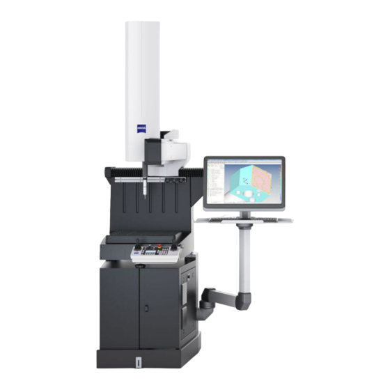
- Page 1 DuraMax Installation site requirements Coordinate measuring machine (CMM)
- Page 2 DuraMax Installation site requirements 2020-12-01 61221-3011202...
-
Page 3: Table Of Contents
Note on data systems ........................... 5 Coordinate measuring machine parameters .................. 5 Logistics and In-plant Transport................. 6 Unloading/ in-plant transport........................ 6 Shipping crates for DuraMax......................... 7 Intermediate storage/unpacking...................... 7 Adaptation to room temperature ...................... 7 Relocating an installed CMM ........................ 7 Planning and Measuring Lab Preparation ............ 9... - Page 4 Securing the standard base ......................... 16 DuraMax with ShopFloor base ...................... 17 Securing the shopfloor base........................ 18 DuraMax measuring table with threaded holes ................... 19 Limit curves of permissible floor vibrations at the installation site.... 20 Explanation for the diagrams ...................... 20 Permissible foundation acceleration for DuraMax ................
-
Page 5: General
To ensure trouble-free operation of the coordinate measuring machine, you must only use computer systems tested and approved by ZEISS. If the customer provides the computer systems, the computers must first be tested and approved by ZEISS. -
Page 6: Logistics And In-Plant Transport
➁ – A crane or forklift with the following properties is required to lower DuraMax onto a table or base (option). Fork length: ≥1000 mm, fork thickness: ≥40 mm over ≥700 mm, separation of the fork arms: outer dimensions ≤420 mm, inner dimensions ≥120 mm. -
Page 7: Shipping Crates For Duramax
— The CMM must remain inside the protective cover at its final installation site for at least 24 hours before the cover is opened or removed. This is the only way to prevent rust damage due to condensation. — Only a ZEISS service technician or specially trained personnel are authorized to remove the pro- tective cover. NOTE Packing materials such as disposable transport packaging, covers or Styrofoam chips are reused by ZEISS and can be returned to ZEISS. - Page 8 Preparatory measures: — The measuring table must be clear — Remove probe. — The control console and the control console holder must be removed. — If a changer rack is installed, it must also be removed. DuraMax Installation site requirements...
-
Page 9: Planning And Measuring Lab Preparation
CMM from the rest of the foundation. Installation sites over a cellar or on upper floors of a building must also be avoided. For many ZEISS coordinate measuring machines, there is also an additional option for an air damping system that can efficiently dampen floor vibration is certain frequency ranges. -
Page 10: Environmental Conditions
If you are not sure if your installation site is suitable for a ZEISS coordinate measuring machine, a vibration analysis can be completed at your site and our specialists will provide you with a non-binding recommendation. Please contact your ZEISS representative if you require more information about this. -
Page 11: Electrical Specifications And Network Data
If required, please contact us for more information. We will be glad to assist you and recommend suitable mea- sures. Usually, separate stub cables from the main distribution frame to the connection point of the CMM are suffi- cient. DuraMax Installation site requirements... -
Page 12: Required Connections
A 5-outlet (or more) power strip (to be provided by the customer). Power for the CMM must be supplied by one of the wall outlets. The power cable with corresponding plug is connected to the controller of the CMM by ZEISS service technicians dur- ing the initial installation. -
Page 13: Network Connection
An Internet connection is not required for the installation of the CMM. Network topology System components are networked during start-up by a ZEISS service engineer (or a specialist authorized by ZEISS) in accordance with the applicable specifications and must not be modified by the customer. Any change may lead to connection problems. -
Page 14: Footprint/ Sample Installation/ Weights
Front and side view/ M 1:30/ dimensions in millimeters For the installation of DuraMax, you can also use a sturdy table as a base. It should be at least 700 mm high and must be designed to bear a load of ≥450 kg. (Provided by customer). -
Page 15: Duramax With Standard Base
DuraMax with standard base Front and side view/ M 1:30/ dimensions in millimeters 1 Network connection for data backup and Internet (Teleservice) 2 2x shock-proof (Schuko) wall outlets 4 5 6 3 5-outlet power strip (to be provided by the customer) -
Page 16: Securing The Standard Base
The plug screws are not tightened. There must be a gap of 1-2 mm between the head of the plug screw and the base. This provides the necessary tilt protection and does not have a negative effect on the 3-point support of the base. DuraMax Installation site requirements... -
Page 17: Duramax With Shopfloor Base
DuraMax with ShopFloor base Front and side view/ M 1:30/ dimensions in millimeters 1 Network connection for data backup and Internet (Teleservice) ‚ 2 2x shock-proof (Schuko) wall outlets 3 Power cable: power supply for CMM ƒ 4 Power cable: power supply for data system 5 Swivel arm range for monitor, keyboard and mouse 60°... -
Page 18: Securing The Shopfloor Base
Risk of tipping if not properly anchored If the floor covering is too thick and the plug screws cannot be anchored sufficiently as a result, there is a risk of tipping. — In this case, customers must provide sufficiently long plug screws. DuraMax Installation site requirements... -
Page 19: Duramax Measuring Table With Threaded Holes
DuraMax measuring table with threaded holes M10 (25x) 200±0,1 100±0,1 100±0,1 200±0,1 200±0,1 100±0,1 100±0,1 200±0,1 494 x 494 Measuring table/ M 1:4/ all dimensions in millimeters DuraMax Installation site requirements... -
Page 20: Limit Curves Of Permissible Floor Vibrations At The Installation Site
If none of the given diagrams applies to your configuration, the diagrams for other sizes can be used for orientation. Please contact your ZEISS representative if you require more information about this. Permissible foundation acceleration for DuraMax Note: Acceleration values above the corresponding curve require additional damping. - Page 21 DuraMax Installation site requirements...
- Page 22 DuraMax Installation site requirements 2020-12-01 61221-3011202...
Need help?
Do you have a question about the DuraMax and is the answer not in the manual?
Questions and answers