
Related Manuals for Zeiss OPMI Lumera i


Summary of Contents for Zeiss OPMI Lumera i
- Page 1 ZEISS ® OPMI Lumera on the floor stand Instructions for Use G-30-1720-en Version 8.0 2018-11-26...
- Page 2 – A list of abbreviations, key words, and technical terms in the annex facilitates the search for specific terms. Scope These Instructions for Use apply to the OPMI Lumera i with the following identification: – Reference number: 6633 – Software Release 1.5...
- Page 3 OPMI Lumera i Summary of the section Section: Safety measures Section: Device overview Section: Preparation for use Section: Operation Section: What to do in the event of malfunctions Section: Care and maintenance Section: Device data Section: Indexes Version 8.0 G-30-1720-en...
- Page 4 OPMI Lumera i Version 8.0 Page 4 G-30-1720-en...
-
Page 5: Table Of Contents
OPMI Lumera i Safety measures Safety measures Key to symbols .................. 7 Hazard symbols ...................7 Information symbols..................7 Target group ..................8 Field of use ..................8 Intended use ....................8 Normal use....................8 Notes for the operator............... 9 Duties of the operator .................9 Requirements to be met by the user ............12... - Page 6 Safety measures OPMI Lumera i Switch for manual mode................24 Locking lever for limiting vertical movement ..........26 Position of the microscope with fundus imaging system ......26 Symbols and labels on the device ............28 Version 8.0 Page 6 G-30-1720-en...
-
Page 7: Key To Symbols
OPMI Lumera i Safety measures Key to symbols We would like to inform you about safety requirements with which you must comply when working with this system. This chapter contains a summary of the most important information concerning matters relevant to instrument safety. -
Page 8: Target Group
ZEISS. Field of use Intended use OPMI Lumera i is a surgical microscope intended for the illumination and magnification of the surgical area and for the support of visualization in surgical procedures in the field of ophthalmology. -
Page 9: Notes For The Operator
• Please comply with the Instructions for Use of the other system components as well. You can obtain additional information from ZEISS Service. • The Instructions for Use contain warnings and safety information that describe the possible residual risks. - Page 10 • Switch off the system at the power switch if you notice any smoke, sparks, or unusual noise. Do not use the unit until it has been repaired by the ZEISS Service team. A potential equalization connector is provided on the instrument’s connection panel (see IEC 60601-1).
- Page 11 The system may be transported over long distances (e.g., during relocation, return for repair, etc.) only in its original packaging or in special return packaging. Please contact your dealer or ZEISS Service for this purpose. • If there is a failure and you cannot resolve the issue using information in the chapter “What to do in the event of malfunctions”, attach an “Out of...
-
Page 12: Requirements To Be Met By The User
Never use force when trying to connect any electrical connectors (plugs, sockets). If connection is not readily possible, check whether the plug fits the socket. If any of the connectors are damaged, have the Carl Zeiss service team repair them. - Page 13 OPMI Lumera i Safety measures You must not use stored video sequences, video clips (extracted sequences), Not for diagnostic purposes single images and live images for diagnostic purposes. Since the video cameras and monitors have not been calibrated, the visualized video sequences, video clips and single images may include deviations in scale, color and shape.
-
Page 14: Requirements For Operation
Safety measures OPMI Lumera i Requirements for operation A ZEISS Service representative or an expert authorized by ZEISS will install the system. Please make sure that the following requirements continue to be met for further operation: The connecting components have been properly connected. The screw connections have been firmly tightened. -
Page 15: During Use
Adjust the illumination intensity and the resulting radiation exposure time by selecting the appropriate illumination setting. The values recommended by ZEISS are located in the table “Maximum radiation exposure times” on Page 20. Deviations from these values must be medically justified and are the sole responsibility of the surgeon. -
Page 16: Measures To Prevent Phototoxic Injury
– Exposure time to light In the following, comments on these aspects are given and a description of how ZEISS, as a manufacturer, makes allowance for them in its systems. Illumination characteristics (spectral composition) Studies on exposing the eye to light with varying spectral compositions have been conducted since as early as the 1950s. -
Page 17: Illumination Intensity
Brightness control ZEISS has addressed this aspect by providing its devices with a feature for continuously varying the brightness of the light source. This permits the surgeon to optimally adapt the light intensity at the patient’s eye to the conditions existing in each case. -
Page 18: Exposure Time To Light
This problem has been solved by ZEISS by the use of a swing-in retina protection filter (blue barrier filter) that can be swung into the microscope’s illumination beam path. - Page 19 The peripheral illumination causes higher exposure of the retina, but, depending on the position of the eye, usually not the macula directly. For cataract procedures, ZEISS recommends adjusting the surrounding field illumination to be somewhat darker than the central red reflex spot.
- Page 20 Safety measures OPMI Lumera i – totally immobile eye, which means that only one area is subject to exposure, – pupil dilated to 8 mm. The calculations are based on the daily exposure limits recommended for occupational safety as defined in .
- Page 21 OPMI Lumera i Safety measures H. Stiller, and B. Rassow, “Light hazards to the patient’s retina from ophthalmic List of references instruments,” Applied Optics-OT 30, 2187-2196 (1991). American Conference of Governmental Industrial Hygienists, “Documentation of the Threshold Limit Values for physical agents. 7th Edition,” (American Conference of Governmental Industrial Hygienists, Cincinnati, 2001).
-
Page 22: Safety Features
Safety measures OPMI Lumera i Safety features Button for backup lamp 1 Button for manual activation of the backup lamp If the automatic lamp changing system fails, press this button to activate the backup lamp. Filter wheel for the protection filter... - Page 23 OPMI Lumera i Safety measures Fig. 1: Button for backup lamp and knob for protection filter Version 8.0 G-30-1720-en Page 23...
-
Page 24: Switch For Manual Mode
Safety measures OPMI Lumera i Switch for manual mode 3 Switch for manual mode In the event of failure of one of the major functions (XY movement, focus, zoom, light control) and impairment of further functions, you can press this switch to change to manual mode. - Page 25 OPMI Lumera i Safety measures Fig. 2: Switch for manual mode Version 8.0 G-30-1720-en Page 25...
-
Page 26: Locking Lever For Limiting Vertical Movement
Only use accessories expressly certified by ZEISS for combination with the surgical microscope described in this manual. - Page 27 OPMI Lumera i Safety measures Fig. 3: Locking lever for limiting vertical movement Version 8.0 G-30-1720-en Page 27...
-
Page 28: Symbols And Labels On The Device
Symbols and labels on the device CAUTION Please comply with the warning labels and notices! • If you notice that any of these labels/signs is missing on your device or has become illegible, please contact ZEISS Service. Symbol Name Explanation Warning label... - Page 29 OPMI Lumera i Safety measures Symbol Name Explanation Maximum load When the surgical microscope and X-Y coupling have been mounted, the weight of additional accessories on the suspension arm must not exceed 5.5 kg. Friction symbol Indication for friction setting Consult Instructions Observe the Instructions for Use.
- Page 30 – Manufacturer’s symbol – Manufacturer’s address: Goeschwitzer Strasse 51–52 7745 Jena, Germany – Serial number: 663312xxxx – Device name: OPMI Lumera i – Rated voltage: (115 V): 100–125 V (230 V): 220–240 V – Connected load: (115 V): max. 950 VA (230 V): max.
- Page 31 – Manufacturer (company name) – Contact details for the manufacturer, i.e., phone number, fax number, and e-mail address of the local contact of the national ZEISS sales XXXX XXXXXX organization. – SIP number A unique identification number assigned to your system.
- Page 32 Safety measures OPMI Lumera i Version 8.0 Page 32 G-30-1720-en...
- Page 33 OPMI Lumera i Device overview Device overview System overview................34 Components of the microscope ............36 Controls on the microscope...............38 Controls for the tubes................42 Controls for the widefield eyepieces ............43 Components on the suspension system ........... 44 Control elements on the suspension arm ...........45 Controls on the carrier arm, stand column, stand base ......46...
-
Page 34: System Overview
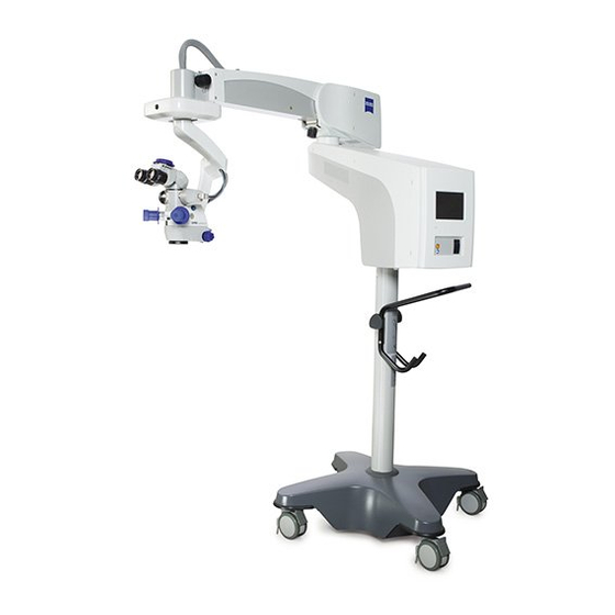
Device overview OPMI Lumera i System overview The OPMI Lumera i comprises the following key components: 1 Microscope for the magnified visualization of the field of view. 2 X-Y coupling for precise movement of the microscope in the horizontal X-Y plane. - Page 35 OPMI Lumera i Device overview Fig. 4: System overview Version 8.0 G-30-1720-en Page 35...
-
Page 36: Components Of The Microscope
Device overview OPMI Lumera i Components of the microscope 1 Tube – 180° tiltable tube (standard) This tube can be turned by 180°, allowing surgeons to sit upright even if the microscope is tilted. – Tube with 45° (standard) The tube cannot be pivoted and the tube is therefore mainly suitable for tasks performed while the microscope is in a vertical position. - Page 37 OPMI Lumera i Device overview Fig. 5: Components of the microscope Version 8.0 G-30-1720-en Page 37...
-
Page 38: Controls On The Microscope
Device overview OPMI Lumera i Controls on the microscope 1 DOF button (DeepView depth of field management system) for selecting between optimum light transmission and maximum depth of field. When deactivated (LED not lit), the microscope is optimized for light transmission. When this function is activated (green LED is lit), the microscope is automatically set to the optimum depth of field in accordance with the selected magnification. - Page 39 OPMI Lumera i Device overview Fig. 6: Controls on the microscope Version 8.0 G-30-1720-en Page 39...
- Page 40 Device overview OPMI Lumera i 5 Arrows indicating the focusing range If the dot is located between the two arrow tips the focusing system of the surgical microscope is in its starting position. 6 Tilting device – For tilting the microscope into a position convenient for you (vertical starting position).
- Page 41 OPMI Lumera i Device overview Fig. 7: Controls on the microscope Version 8.0 G-30-1720-en Page 41...
-
Page 42: Controls For The Tubes
Device overview OPMI Lumera i Controls for the tubes 180° tiltable tube and inclined tube 1 Eyepiece mounting 2 Eye distance adjustment wheel (interpupillary distance) The correct position has been reached when the two eyepiece images merge into one. You can read off the PD setting on the adjustment knob. -
Page 43: Controls For The Widefield Eyepieces
OPMI Lumera i Device overview Controls for the widefield eyepieces NOTE Widefield eyepieces with magnetic coupling When handling eyepieces that have been removed from the tube, please keep in mind the usual rules for handling magnets: • Do not place the eyepiece near instruments which may be magnetizable. -
Page 44: Components On The Suspension System
Device overview OPMI Lumera i Components on the suspension system The suspension system is used to position and control the microscope. It comprises the following components: 1 Suspension arm with lamp housing. When the suspension arm is moved forward, the surgical microscope is located in the park position. In this position, the light turns off and the OPMI is reset to the user-specific start values, e.g., XY or focus reset (see Page 122). -
Page 45: Control Elements On The Suspension Arm
OPMI Lumera i Device overview Control elements on the suspension arm 1 Balancing knob Balance for balancing the surgical microscope. 2 Locking lever for limiting vertical movement for setting the lower limit position see Page 80. 3 Friction adjustment knob for rotation of the surgical microscope for adjusting the friction of the axis of rotation of the surgical microscope. -
Page 46: Controls On The Carrier Arm, Stand Column, Stand Base
Device overview OPMI Lumera i Controls on the carrier arm, stand column, stand base 1 Control and display panel with 5.7" control panel 2 Friction adjustment knob for the suspension arm’s swivel movement 3 Friction adjustment knob for the carrier arm’s swivel movement... -
Page 47: Controls On The Lamp Housing
OPMI Lumera i Device overview Controls on the lamp housing The lamp housing is designed for fiber illumination and is equipped with a halogen light source. The lamp housing contains a backup lamp which automatically swings into the illumination beam path when the first lamp fails. -
Page 48: Connector Panel On The Floor Stand
ZEISS Service. 6 Ethernet connection (optional) for future linking of OPMI Lumera i and CALLISTO eye. You can find the requirements for integrating the device into an existing IT network (as defined by IEC 60601-1) on Page 151. - Page 49 OPMI Lumera i Device overview Fig. 14: Connectors on the floor stand Version 8.0 G-30-1720-en Page 49...
- Page 50 500 VA CAUTION Danger! Electrical voltage! Only connect accessories and medical devices designated by ZEISS for use with this system to the power outlet sockets. • When connecting other devices, make sure that safety is guaranteed regarding admissible touch currents and ground leakage currents according to IEC 60601-1.
- Page 51 OPMI Lumera i Device overview Fig. 15: Connectors on the floor stand 11 12 Version 8.0 G-30-1720-en Page 51...
-
Page 52: Controls On The Control And Display Panel
Device overview OPMI Lumera i Controls on the control and display panel 1 5.7" control panel with touchscreen functionality The 5.7" control panel is the system’s central communication interface. enables the user to configure the settings of the microscope, the suspension system (light source and camera, if provided), and the programmable buttons on the foot control panel. -
Page 53: Components Of The Foot Control Panel
OPMI Lumera i Device overview Components of the foot control panel The foot control panel permits you to control various functions of the suspension system and surgical microscope. The assignment of the functions to the buttons on the foot control panel is shown on the following page. - Page 54 The default settings (focus/zoom) of the rocker switches are pre-configured Rocker switches horizontally or vertically for each country. However, a ZEISS service technician can change the settings at any time. User-specific settings (see Page 110) can be made by you at any time.
-
Page 55: Accessories For Documentation And Co-Observation
OPMI Lumera i Device overview Accessories for documentation and co-observation You can attach various accessories for documentation and co-observation purposes to the system. If a camera control unit (CCU) for 1 CCD or 3 CCD video cameras has been integrated in the factory, you can control and configure the video cameras via the 5.7"... - Page 56 Device overview OPMI Lumera i Connection via beam splitter and C-mount adapter 1 1 CCD video camera 2 C-mount adapter for beam splitter/video camera connection. 3 3 CCD video camera 4 Beam splitter with two optical output ports to which e.g., a co-observation module or a video camera with C-mount adapter can be connected.
-
Page 57: Edis - External Data Injection System (Optional)
Video recording (On/Off) – Assistant functions (Incision/LRI, Rhexis, ZALIGN) You will find additional explanations on EDIS in the ZEISS Instructions for Use “EDIS, External Data Injection System” G-30-1913. Components 1 EDIS module (projection unit with integrated data injection and HD camera) -
Page 58: 1Chip Hd Camera (Option)
Device overview OPMI Lumera i 1Chip HD camera (option) 1 1Chip HD camera (option) flanged to a beam splitter 2 CCU (Camera Control Unit) Control unit for the 1Chip HD camera Version 8.0 Page 58 G-30-1720-en... - Page 59 OPMI Lumera i Preparation for use Preparation for use Relocating the unit ................62 Configuring surgical microscope............64 Changing tubes, eyepieces, or objective lens ..........64 Mounting video and documentation accessories ........66 Connecting the light guide to the surgical microscope.......72 Balancing the system .................73 1Chip HD camera option..............74...
- Page 60 Preparation for use OPMI Lumera i WARNING Risk of serious injury due to unauthorized modification! You must not modify this device without the permission of the manufacturer. The manufacturer is not liable for damages caused by an unauthorized use R502 of the device.
- Page 61 OPMI Lumera i Preparation for use Version 8.0 G-30-1720-en Page 61...
-
Page 62: Relocating The Unit
Preparation for use OPMI Lumera i Relocating the unit CAUTION Risk of crushing - mind your fingers! Fingers may be crushed in the areas marked with the “Risk of crushing” label. • Do not touch these areas while the system is being moved or brought in its working/transport position. - Page 63 The device may be transported over long distances (e.g., relocation, return for repair, etc.) only in its original packaging or in special return packaging. • Please contact your dealer or ZEISS Service for this purpose. Version 8.0 G-30-1720-en Page 63...
-
Page 64: Configuring Surgical Microscope
Never mount or remove accessory equipment on the surgical microscope during surgery. • Only use accessories expressly certified by ZEISS for combination with the surgical microscope described in this manual. • Never exceed the maximum permissible weight capacity of the suspension arm (see Page 148). - Page 65 OPMI Lumera i Preparation for use • Unscrew securing screw (4) by a few turns. • Remove binocular tube (5). • Attach the new binocular tube to the microscope body and firmly tighten securing screw (4). • You can install additional accessories between the binocular tube and the microscope body.
-
Page 66: Mounting Video And Documentation Accessories
Preparation for use OPMI Lumera i Mounting video and documentation accessories You can connect the accessories for co-observation or video documentation to the system. The following connection possibilities exist: Connection via VOL 442/802 video objective lenses (see Page 67) •... - Page 67 OPMI Lumera i Preparation for use Connection via video objective lenses VOL 442/802 Mounting the camera block The following description is based on video objective lens VOL 442. The same process can be used for video objective lens VOL 802.
- Page 68 Preparation for use OPMI Lumera i The following description is based on video objective lens VOL 442. Securing the video objective lens The same process can be used for video objective lens VOL 802. • Unscrew securing screw (4) by a few turns.
- Page 69 OPMI Lumera i Preparation for use The stereo co-observation tube shown in the illustration below is an example Mounting accessories on the video objective lens of accessories that can be mounted on the VOL 442 video objective lens. The procedure described here can also be used for other accessories (e.g., camera adapter).
- Page 70 3.5 mm. A longer thread can damage the camera and definitely results in focus errors of the video lens. If in doubt, please ask your local dealer or ZEISS Service which video lens is suitable for your system. •...
- Page 71 OPMI Lumera i Preparation for use Fig. 24: C-mount adapter Version 8.0 G-30-1720-en Page 71...
-
Page 72: Connecting The Light Guide To The Surgical Microscope
Preparation for use OPMI Lumera i Connecting the light guide to the surgical microscope NOTE Risk of damage to the light guide! • Please note the label under the light guide socket for the correct connection of light guide (1). -
Page 73: Balancing The System
OPMI Lumera i Preparation for use Balancing the system Do not perform balance setting until the surgical microscope and all accessories have been mounted! CAUTION Risk of crushing – mind your fingers! Fingers may be crushed between the carrier and suspension arms. -
Page 74: 1Chip Hd Camera Option
Preparation for use OPMI Lumera i 1Chip HD camera option Installing the 1Chip HD camera Please observe the “1Chip HD camera” Instructions for Use (G-30-1946). These Instructions for Use are included automatically in systems with the “1Chip HD camera” option. They contain all the additional explanations for the “1Chip HD camera”... -
Page 75: Cable Connections For The 1Chip Hd Camera
OPMI Lumera i Preparation for use Cable connections for the 1Chip HD camera CAUTION Risk of electric shock caused by unapproved or defective accessories! Unapproved or defective accessories can cause increased leakage current. The user and patient may suffer an electric shock if the video output ports R506 are touched. -
Page 76: Connecting The System And Accessories
(5) using a suitable tool. CAUTION Danger! Electrical voltage! You may connect only medical devices and accessories designated by ZEISS for this device to the power output socket. When using other devices, make sure that safety is guaranteed regarding admissible ground leakage currents. -
Page 77: Connecting The Foot Control Panel To The Suspension System
OPMI Lumera i Preparation for use Connecting the foot control panel to the suspension system • Make sure that the power switch (1) is OFF. (When the device has been switched on, the green lamp in the switch is lit.) •... -
Page 78: Connecting The Strain Relief
Preparation for use OPMI Lumera i Connecting the strain relief Use the strain relief device to prevent the connected cables inadvertently being pulled out. Make sure that the remaining cable length between the strain relief device and the connector (on the connector panel) is approx. 320 mm. -
Page 79: Connecting Video Devices (Option)
OPMI Lumera i Preparation for use Connecting video devices (option) CAUTION Risk of electric shock caused by unapproved or defective accessories! Unapproved or defective accessories can cause increased leakage current. The user and patient may suffer an electric shock if the signal interfaces or R506 video outputs are touched. -
Page 80: Setting Up The System
Preparation for use OPMI Lumera i Setting up the system Limiting the suspension arm’s downward movement CAUTION Risk of injury caused by lowering of the surgical microscope! If the surgical microscope has not been correctly balanced, it may lead to downward movement and cause injury to the patient. -
Page 81: Positioning The Device In The Or
OPMI Lumera i Preparation for use Positioning the device in the OR Proceed as follows to position the system: • Release all locking devices. • Hold the device by the transport handle (1) and move it carefully into a position convenient for you (such as that shown below). -
Page 82: Tilt Adjustment Motion
Preparation for use OPMI Lumera i Tilt adjustment motion • Tilt the microscope to the required position. The optical axis of the microscope should generally be positioned at right angles to the patient’s eye. Fig. 32: Tilt adjustment motion Version 8.0... - Page 83 OPMI Lumera i Preparation for use Version 8.0 G-30-1720-en Page 83...
-
Page 84: Adjusting The Surgical Microscope
Preparation for use OPMI Lumera i Adjusting the surgical microscope CAUTION Damage to the eyes due to high light radiation! • Never use the sun as a distant target for the adjustment of the surgical microscope described below. • Do not use any other extremely bright light sources as a target. - Page 85 OPMI Lumera i Preparation for use – Emmetropes: Adjusting the eyepieces • Set diopter setting ring (5) to 0 diopters (D). – Eyeglass wearers who perform surgery wearing their eyeglasses: • Set diopter setting ring (5) to 0 dpt. –...
-
Page 86: Preparing The Device For Sterile Use
This also applies to the first use after delivery. These procedures may only be performed by properly trained personnel. For the OPMI Lumera i the following asepsis caps are available (see Page 170 for ordering data): 1 Asepsis cap for interpupillary distance adjustment knob... -
Page 87: Drapes
OPMI Lumera i Preparation for use Drapes You can also use disposable sterile drapes to cover the system. When draping the system, make sure there is enough slack in the drapes to allow for movement of the microscope carrier and surgical microscope. - Page 88 Preparation for use OPMI Lumera i Version 8.0 Page 88 G-30-1720-en...
- Page 89 OPMI Lumera i Operation Operation Powering the device up and down ..........91 Function test before use ..............93 Menu structure ................98 Controls on the 5.7" control panel with touchscreen functionality ...100 User data, management ..............102 Creating new users..................102 Select User ....................103 Change user name...................103...
- Page 90 Operation OPMI Lumera i Configuring 3 CCD video camera (optional) ........116 Assigning video mode................112 Adjusting video mode ................113 White balancing..................119 Performing the black balance procedure ..........120 System settings................121 Configuring XY reset button ..............121 Configuring standby position ..............122 Setting speeds ..................
-
Page 91: Powering The Device Up And Down
The system is switched on if the green lamp in the power switch is lit. After power-up, the system performs a self-test. During this time (approx. 120 seconds) a start screen with the Zeiss logo is displayed on the 5.7" control panel. - Page 92 Operation OPMI Lumera i CAUTION Never leave the device unattended when it is switched on! If a patient or an object is exposed to the light source for a longer period of time, this could cause burns or fire damage.
-
Page 93: Function Test Before Use
OPMI Lumera i Operation Function test before use Checklist Use the following list to check the function of the device before every operation (with no patient). CAUTION Failure of functions possible If defects in the device are identified during surgery, there is a risk of injuries to the patient. - Page 94 Operation OPMI Lumera i • Checking eyepieces/binocular tube/objective lens The surgical microscope and the tube are in a position convenient for you (see Page 81). The interocular distance (pupillary distance) has been correctly set (please refer to Page 84).
- Page 95 OPMI Lumera i Operation • Check the lamp brightness. The lamp brightness can be varied (see Page 107). Brightness adjustment has an effect on the surgical field illumination. • Check the lamps Primary lamp and backup lamp are both intact.
- Page 96 Operation OPMI Lumera i • Check the fundus imaging system (if provided) CAUTION Injury to the patient’s eye due to incorrect operation of the fundus viewing system Incorrect operation of the fundus imaging system may cause injury to the patient’s eye and impair image quality. Perform the following steps to avoid this hazard: •...
- Page 97 OPMI Lumera i Operation Version 8.0 G-30-1720-en Page 97...
-
Page 98: Menu Structure
Operation OPMI Lumera i Menu structure The surgical microscope offers a range of specific setting options which you can select via the 5.7" control panel. The setting options are grouped in menus and submenus. If a menu option is not selectable, the associated button is grayed out. - Page 99 OPMI Lumera i Operation Fig. 35: Menu structure Version 8.0 G-30-1720-en Page 99...
-
Page 100: Controls On The 5.7" Control Panel With Touchscreen Functionality
Operation OPMI Lumera i Controls on the 5.7" control panel with touchscreen functionality Back Press the <Back> button to: – return to the previous menu, – cancel changes, – retain changes until a new user logs in or the system is restarted. - Page 101 OPMI Lumera i Operation Virtual keyboard A virtual keypad is displayed on the 5.7" control panel when text entries are required. You can make all entries on this keypad by touching the keys with your finger. When the menu is activated, the already existing name is entered in the entry box.
-
Page 102: User Data, Management
Operation OPMI Lumera i User data, management The “User” menu enables you to select a default user profile or to create and manage 20 different, freely configurable user profiles. Creating new users • Press the <User> button in the main menu. -
Page 103: Select User
OPMI Lumera i Operation Select User • Press the <User> button in the main menu. The “User” menu is displayed. • Select the current user in the “Choose User” field. If several users exist, a list with a scroll bar is displayed. Click the arrows to scroll up and down. -
Page 104: Setting The Language
Operation OPMI Lumera i Setting the language • Press the <User> button in the main menu. The “User” menu is displayed. • Select the user for whom you want to set the language in the “Choose User” field. The language of the default user cannot be changed. -
Page 105: Light Source
• Adjust the illumination intensity as required for the selected type of illumination and the radiation exposure time. You will find the values recommended by ZEISS in the tables “Maximum radiation exposure times” on Page 20. • Only deviate from these limit values in medically justified cases (IEC 60601-1, point 12.4.1). - Page 106 Operation OPMI Lumera i If a different user logs on, the current status of the light source is retained. When the system is rebooted, the light source is reset to its “Light off” default status. • To save the changes, press the button ...
-
Page 107: Setting The Starting Values Of The Light Source
OPMI Lumera i Operation Setting the starting values of the light source The menu permits you to set the start value for the light intensity. You can change the brightness at any time on the suspension system or foot control panel. -
Page 108: Adjusting Magnification
Operation OPMI Lumera i Adjusting magnification The “Magnification” menu offers you the following functions: – Setting the start value of the zoom system – Display of the total magnification – Setting the zoom/focus link Setting the start value of the zoom system The menu permits you to set a user-specific start value for the zoom system. -
Page 109: Display Of The Total Magnification
OPMI Lumera i Operation Display of the total magnification The calculation of the total system magnification is based on the parameter settings for the objective lens, tube and eyepieces used (see Page 121). • Press the <Magnification> button in the main menu. -
Page 110: Configuring The Foot Control Panel
Rocker switches The default settings (focus/zoom) of the rocker switches are pre-configured horizontally or vertically for each country. However, a ZEISS service technician can change the settings at any time. User-specific settings (see Page 110) can be made by you at any time. -
Page 111: Changing The Button Configuration
OPMI Lumera i Operation The horizontal factory settings are: – Button I: focus – Button G: zoom – Button J: focus – Button H: zoom The vertical factory settings are: – Button I: zoom – Button G: zoom – Button J: focus –... -
Page 112: Configuring 1 Ccd Video Camera (Optional)
Configuring 1 CCD video camera (optional) The “Video” menu is only available to you if your system features a partially integrated 1 CCD or 3 CCD video camera from ZEISS. If a 1 CCD video camera is connected, you can control the following functions: –... -
Page 113: Adjusting Video Mode
OPMI Lumera i Operation Adjusting video mode You can configure the video modes to meet your specific requirements regarding the exposure mode (brightness) and image orientation. In addition, you can perform a white balance procedure which compensates for the effects of different light sources on the color rendition of the camera. - Page 114 Operation OPMI Lumera i – “Integral” (standard) The exposure is measured and averaged across the full video image. This measurement is recommended for surgical fields that are fully and evenly lit. – “Large Spot” (large) The exposure is measured in the area in the image center. This measurement is ideal for working with an eclipsed surgical field edge (resulting from a reduced illuminated-field diameter).
- Page 115 OPMI Lumera i Operation White balancing In the white balance procedure, the system adjusts the video signal in such a way that white areas in the surgical field are also white on the monitor. • Press the <Video><Edit><White Balance> buttons in the main menu.
-
Page 116: Configuring 3 Ccd Video Camera (Optional)
Configuring 3 CCD video camera (optional) The “Video” menu is only available to you if your system features a 1 CCD or 3 CCD video camera from ZEISS. If a 3 CCD video camera is connected, you can control the following functions: –... - Page 117 OPMI Lumera i Operation Adjusting video mode You can configure the video modes to meet your specific requirements regarding color saturation, exposure mode (brightness), and image orientation. In addition, you can perform a white balance or black balance procedure which compensates for the effects of different light sources on the color rendition of the camera.
- Page 118 Operation OPMI Lumera i • Press the <Manual Brightness> button. Automatic exposure Automatic exposure control is active when the “Manual Brightness” button lights up light blue. The display of the brightness setting range changes from exposure time (seconds) to percent (%).
-
Page 119: White Balancing
OPMI Lumera i Operation White balancing In the white balance procedure, the system adjusts the video signal in such a way that white areas in the surgical field are also white on the monitor. • Press the <Video><Edit><White Balance> buttons in the main menu. -
Page 120: Performing The Black Balance Procedure
Operation OPMI Lumera i Performing the black balance procedure In the black balance procedure, the system adjusts the video signal in such a way that black areas in the surgical field are also black on the monitor. • Press the <Video><Edit><Black Balance> buttons in the main menu. -
Page 121: System Settings
OPMI Lumera i Operation System settings The “System Settings” menu enables you to make the following settings: – Configuring XY reset button – Configuring standby position – Configuring system options – Optical settings – Network (optional) – Versions – FCP pairing (optional) –... -
Page 122: Configuring Standby Position
Operation OPMI Lumera i • Select the functions to be started when the XY reset button is pressed. The following functions are available: – XY Reset (The X-Y coupling moves to its center position.) – Focus Reset - always active (The focusing system moves to its initial position.) -
Page 123: Setting Speeds
OPMI Lumera i Operation • To save the changes, press the button. The setting is saved for the current user. • To return to the Main Menu, press the button 2×. The main menu is displayed again. Setting speeds This submenu permits you to set the focus, XY and zoom speeds to meet your specific requirements. -
Page 124: Setting Parameters For Total Magnification
Operation OPMI Lumera i Setting parameters for total magnification To ensure correct display of the total magnification, the parameters of the objective lens, tube, and eyepieces used must be set. The settings are applied for all users. • Select <System Settings><System Options><Optical Settings> in the main menu. - Page 125 OPMI Lumera i Operation Pairing • Select <System Settings><System Options><FCP Pairing> in the main menu. The “Pairing” menu is displayed. • Put the foot control panel in its vertical position in the immediate vicinity of the system (max. distance of 1 m) and keep it in this position until pairing is finished.
-
Page 126: Typical Procedure
• Adjust the illumination intensity and the resulting radiation exposure time by selecting the appropriate illumination setting. You will find the values recommended by ZEISS in the table “Maximum radiation exposure times” on Page 20. • When operating on the eye, use the retina protection filter (blue barrier filter). - Page 127 OPMI Lumera i Operation CAUTION Unintentional movement of the device If a focus movement is triggered by incorrect operation, this can cause the device to come into contact with the patient’s eye, especially if an accessory (e.g., Visulux, BIOM, fundus viewing system) is installed on the surgical microscope.
- Page 128 Operation OPMI Lumera i CAUTION Never leave the device unattended when it is switched on! If a patient or an object is exposed to the light source for a longer period of time, this could cause burns or fire damage. Excessive radiation exposure times may lead to retinal injury in the patient’s eye.
- Page 129 OPMI Lumera i What to do in the event of malfunctions What to do in the event of malfunctions Failure of the halogen light source ..........130 Failure of a main function (XY, fcs, zom, light) ......131 Troubleshooting ................132 For your safety ..................132...
-
Page 130: Failure Of The Halogen Light Source
What to do in the event of malfunctions OPMI Lumera i Failure of the halogen light source NOTE Overheating of the lamp module! If ventilation grids (1) are covered, e.g., by drapes, this may lead to overheating of the lamp modules and deactivation of the lamp. -
Page 131: Failure Of A Main Function (Xy, Fcs, Zom, Light)
OPMI Lumera i What to do in the event of malfunctions Failure of a main function (XY, fcs, zom, light) In the event that one of the major functions fails (XY movement, focus, zoom, light control), leading to the impairment of further functions, you can switch to the manual mode to complete a surgical procedure that has already been started. -
Page 132: Troubleshooting
If there is a failure and you cannot resolve the issue using information in the chapter “What to do in the event of malfunctions”, attach a sign “Out of order” to the system and contact a ZEISS service representative. Faults in the system... - Page 133 OPMI Lumera i What to do in the event of malfunctions Fault Possible reason Corrective measure Cross reference Surgical field illumination on Light guide not properly Insert light guide as far as it Page 72 microscope not working. inserted in microscope.
- Page 134 What to do in the event of malfunctions OPMI Lumera i Fault Possible reason Corrective measure Cross reference Red reflex too dark or non- Red reflex illumination not Activate red reflex Page 38 existent. activated. illumination. Contaminants on objective Clean objective lenses.
-
Page 135: Malfunctions Of The Fcp Foot Control Panel
The following table contains examples of error messages and the corresponding remedies. If you have problems eliminating the malfunction or if errors keep recurring, do not continue using the system and contact ZEISS Service. You will find the contact responsible for your country on the following website: www.meditec.zeiss.com... - Page 136 What to do in the event of malfunctions OPMI Lumera i Error message Possible reason Corrective measure Cross reference Zoom error. The error can be – e.g., jammed hardware If the error impairs your work, Page 131 acknowledged. switch to the manual mode.
- Page 137 OPMI Lumera i Care and maintenance Care and maintenance Device maintenance............... 138 Maintenance intervals................138 Safety check ....................139 Changing the halogen lamp ..............140 Care of the device................142 Cleaning ....................142 Sterilization .....................143 Disinfection .....................143 Environmental protection measures ..........144 Notes on disposal ..................144 Version 8.0...
-
Page 138: Device Maintenance
The maintenance activities that you are able to perform yourself are described below. Any other maintenance activities that is not described here in detail requires device-specific knowledge. Please contact your local ZEISS Service or authorized partner to arrange for the timely performance of these maintenance activities. Interval Maintenance tasks... -
Page 139: Safety Check
OPMI Lumera i Care and maintenance Safety check CAUTION Risk of injury without safety inspection! Hazards and device deficiencies will not be detected in time and can have a negative effect on patients, users, or others. • Have a safety inspection in compliance with IEC 62353 performed on time and to the prescribed extent. -
Page 140: Changing The Halogen Lamp
Care and maintenance OPMI Lumera i Changing the halogen lamp “Instructions for Use” sign Observe the Instructions for Use or further applicable documents. The following steps are required for changing the lamp: • Turn off the device at the power switch. - Page 141 OPMI Lumera i Care and maintenance Always make sure before surgery that both the primary lamp and backup lamp are intact. Fig. 38: Changing the halogen lamp 9 10 Version 8.0 G-30-1720-en Page 141...
-
Page 142: Care Of The Device
For regular cleaning of the surgical microscope’s objective lenses and eyepieces, we recommend using the optics cleaning kit available from ZEISS. For the catalog number, please see the section “System data – Ordering data”. Fogging of optical surfaces To protect the eyepiece optics from fogging, we recommend using an anti- fogging agent. -
Page 143: Sterilization
OPMI Lumera i Care and maintenance Sterilization The asepsis sets available from ZEISS contain rubber caps and hand grips that can be sterilized in autoclaves. For detailed information on sterilization, please see the enclosed instructions “Preparation of resterilizable products” for the respective asepsis set. -
Page 144: Environmental Protection Measures
Care and maintenance OPMI Lumera i Environmental protection measures Notes on disposal User information on the disposal of electrical and electronic devices This symbol means that the product must not be disposed of as normal domestic waste. The correct disposal of electrical or electronic devices helps to protect the... - Page 145 OPMI Lumera i Device data Device data Technical data ................146 Essential performance features OPMI Lumera i ........146 Ethernet connection (option), requirements for integrating the device into an existing IT network ............151 Accessories....................153 Guidelines and manufacturer’s declaration concerning electromagnetic compatibility ............156 EMC –...
-
Page 146: Technical Data
OPMI Lumera i Technical data Essential performance features OPMI Lumera i The OPMI Lumera i does not have any essential performance features as defined in IEC 60601-1. In lieu of testing the device’s essential performance features, certain device functions defined by the manufacturer were tested. - Page 147 OPMI Lumera i Device data Optics Component Feature Magnification 3.4x – 20.6x (with f = 200 mm objective lens and 10x wide-field eyepieces) Motorized zoom system with apochromatic lens, zoom ratio 1:6 Magnification factor γ = 0.4x – 2.4x Focus...
- Page 148 Device data OPMI Lumera i Mechanics Component Feature Microscope tilt With self-locking control gear, manually adjustable mechanism via rotary knob. Tilt angle < ±90° X-Y coupling Travel range: max. 61 mm x 61 mm Automatic centering at the touch of a button Weight of microscope Approx.
- Page 149 OPMI Lumera i Device data Fig. 39: Dimensional drawing of OPMI Lumera i Version 8.0 G-30-1720-en Page 149...
- Page 150 Device data OPMI Lumera i Electrical system Component Feature Power supply Only connect the system to wall outlets which are equipped with a properly connected protective ground conductor. Rated Voltage (115 V): 100–125 V (230 V): 220–240 V Current consumption (115 V): max.
-
Page 151: Ethernet Connection (Option), Requirements For Integrating The Device Into An Existing It Network
OPMI Lumera i Device data Ethernet connection (option), requirements for integrating the device into an existing IT network • When connecting the device to an existing IT network, comply with the following specifications and measures in accordance with IEC 60601-1: –... - Page 152 Device data OPMI Lumera i Integration of the device in an IT network which includes other ME devices may lead to risks for patients, operators, or other persons that were not previously known. – The operator of the device must determine, analyze, evaluate, and control these risks before the device is connected to the IT network.
-
Page 153: Accessories
OPMI Lumera i Device data Accessories 1 CCD PAL video camera (option) Component Feature Image sensor 1/2" interline transfer CCD image sensors with 752 (H) x 582 (V) pixels Horizontal resolution 480 lines (at 752 pixels) Signal-to-noise ratio 50 dB (with Y/C signal) - Page 154 Device data OPMI Lumera i 3 CCD PAL video camera (option) Component Feature Image sensor Three 1/2" interline transfer interlace scan CCD image sensors Horizontal resolution 800 lines Vertical resolution In accordance with PAL standard Signal-to-noise ratio 62 dB Scanning system...
- Page 155 OPMI Lumera i Device data 3 CCD NTSC video camera (option) Component Feature Image sensor Three 1/2" interline transfer interlace scan CCD image sensors Horizontal resolution 800 lines Vertical resolution In accordance with NTSC standard Signal-to-noise ratio 62 dB Scanning system...
-
Page 156: Guidelines And Manufacturer's Declaration Concerning Electromagnetic Compatibility
WARNING Functional deterioration! Do not install or operate the OPMI Lumera i in close proximity to other devices (with the exception of the combination of the devices described in these Instructions for Use), as this can impair the functioning of the OPMI Lumera i. - Page 157 CISPR. • Do not use the OPMI Lumera i when it is located next to or stacked on top of other devices. • If operation next to or stacked on top of other devices is unavoidable, the OPMI Lumera i must be monitored to ensure that it is operating normally in this configuration.
-
Page 158: Emc - Electromagnetic Compatibility Iec 60601-1-2
Electromagnetic interference The OPMI Lumera i is intended for operation in an electromagnetic environment as specified below. The customer or the user of the OPMI Lumera i is responsible for ensuring that the device is operated in such an environment. -
Page 159: Electromagnetic Immunity For All Me Equipment And Systems
Electromagnetic immunity for all ME equipment and systems The OPMI Lumera i is intended for operation in the electromagnetic environment specified below. The customer or the user of the device OPMI Lumera i is responsible for ensuring that it is operated in such an environment. -
Page 160: Electromagnetic Immunity For Me Equipment And Systems That Are Not Life-Sustaining
The OPMI Lumera i is intended for operation in the electromagnetic environment specified below. The customer or the user of the OPMI Lumera i is responsible for ensuring that the device is operated in such an environment. Electromagnetic immunity... -
Page 161: System Enhancements
OPMI Lumera i Device data System enhancements The device OPMI Lumera i can be extended with the accessories offered by ZEISS (see ordering data/accessories) to form an already tested system. This device combination has been approved by ZEISS. As per IEC 60601-1, this system’s power outlet is a multiple electrical outlet intended for use with an ME system. -
Page 162: Ordering Data
Device data OPMI Lumera i Ordering data Only operate the device using the accessories recommended by ZEISS and included in the delivery package. To find the contact person responsible for orders in your country, visit: www.zeiss.com/med For authorized ZEISS partners, the contractual product configurations, accessories and spare parts apply. -
Page 163: Components For The Surgical Microscope
Objektive lens f = 200 mm with support ring (optional) 302672-9904-000 Objektive lens f = 225 mm with support ring (optional) 302673-0000-000 Further accessories Description Order number Instructions for Use G-30-1720: 000000-1528-709 "OPMI Lumera i on floor stand" Version 8.0 G-30-1720-en Page 163... - Page 164 Device data OPMI Lumera i Cleaning agents Description Order no. Optics cleaning kit 000000-1216-071 Microfiber cleaning cloth 000000-1254-655 Stereo co-observation modules and assistant’s microscopes Description Order number Stereo co-observation module, complete with inverter tube and 12.5x eyepieces: – Stereo co-observation module with 2 pivot joints 000000-1063-869 –...
- Page 165 OPMI Lumera i Device data Description Order number – Straight binocular tube, f = 170 mm 303765-0000-000 – 12.5x push-in widefield eyepiece, asph. 305543-9901-000 – Sleeve for tubes with screw thread 305542-0107-000 Stereo co-observation module, complete with straight tube and 10x eyepieces –...
- Page 166 Beam splitter for the 1Chip HD camera: – Splitter 20 (beam splitter 20) 301503-9901-000 With the “1Chip HD Camera” option for OPMI Lumera i, you automatically receive the “1Chip HD Camera” Instructions for Use (G-30-1946). Video accessories Description Order number Monitors - external –...
- Page 167 Splitter 20 (beam splitter 20) 301513-9901-000 With the “1Chip HD Camera” option for OPMI Lumera i, you automatically receive the “1Chip HD Camera” Instructions for Use (G-30-1946). UC foot control panel for zoom and focus – S7 foot control panel for zoom and focus 305946-9200-000 –...
- Page 168 Device data OPMI Lumera i Foot control panel Description Order no. Wireless Foot Control Panel – Foot control panel with 14 functions, wireless 304970-9020-000 (FCP WL) Back-up cable for wireless foot control panel – 3 m cable for foot control panel with 14 functions (FCP &...
- Page 169 OPMI Lumera i Device data EDIS Description Order number EDIS consisting of: 302755-9004-000 – EDIS module with integrated HD camera – EDIS Box – CCU EDIS cable set consisting of: – EDIS Box cable set 10 m for EDIS module 302755-8640-000 –...
- Page 170 51 cm × 150 cm) package with 10 drapes 306079-0000-000 – Drapes (type 84 ZEISS VisionGuard drapes only for the microscope body, dimensions: 46 cm × 33 cm) package with 10 drapes 306084-0000-000 Version 8.0 Page 170...
-
Page 171: Compliance
OPMI Lumera i Device data Compliance Directives and standards with which the device complies: – The device complies with Medical Device Directive 93/42/EEC: Class I It is labeled with: – This device satisfies the US American and Canadian safety regulations for medical electrical devices/systems. -
Page 172: Environmental Conditions
Device data OPMI Lumera i Environmental conditions For operation Feature Admissible range Temperature + 10 °C … + 40 °C Relative humidity 30% … 75% Air pressure 700 hPa … 1060 hPa For transport and storage Feature Admissible range Temperature Without 1Chip HD camera: - 25 °C …... - Page 173 OPMI Lumera i Indexes Indexes List of technical terms Term Explanation Apochromat Optical system with maximum correction of chromatic aberration Drapes Sterile covers for surgical microscopes Inverter Used in surgery of the back part of the eye. It corrects the orientation of the image by using the fundus imaging system or wide angle optics.
- Page 174 Indexes OPMI Lumera i Term Explanation Communauté Européenne (European Community) - The manufacturer declares that the device complies with the directives of the European Union. Canadian Standards Association (a non-governmental organization that test and certifies product safety) Depth of Field management system...
- Page 175 OPMI Lumera i Keyword index Numbers 1Chip HD camera, mounting ..............74 Accessories .....................153 attaching ....................66 overview ....................55 Adjusting magnification ................108 After every use ..................15 Ambient conditions ..................10 Area of application ..................8 Asepsis caps ...................170 Asepsis sets ....................86 Assigning the foot control panel buttons ..........111 Balancing knob ..................45...
- Page 176 OPMI Lumera i Connecting the light guide ................72 Connection ....................48 ethernet ....................48 foot control panel ................48 potential equalization .................48 power input ..................48 power output ..................50 remote ....................48 USB for service purposes ..............48 video lenses ..................67 Controls 5.7" control panel ................100 control and display panel ..............52...
- Page 177 OPMI Lumera i EMC – Electromagnetic compatibility ............158 Emergency backup power supply ...............9 Environmental conditions ...............172 Environmental protection measures ............144 Error messages ..................135 Ethernet connection (optional) ...............151 Exposure mode ................113 External Data Injection System ..............57 Eyepiece changing ....................64 setting ....................85 Eyes adjusting distance ................84...
- Page 178 OPMI Lumera i Illumination ....................36 Illumination characteristic .................16 Illumination knob ..................38 Image orientation ................114 Inclined tube .....................36 Information symbols ...................7 Intended use ....................8 Inverter tube .....................36 Key to symbols ...................7 Legal regulations ..................9 Light source configuring ..................105 start value ..................107 switching on/off ................105...
- Page 179 OPMI Lumera i Normal use ....................8 Opening the lamp module ................47 Operating procedure ................126 Operation ....................89 Optical surfaces, cleaning ...............142 Option, 1Chip HD camera .................74 Ordering data ..................162 EDIS ....................169 Pairing with wireless foot control panel ..........124 Parameters for total magnification ............124 Performing black balance procedure ............120...
- Page 180 OPMI Lumera i Stand ......................34 column ....................44 connecting ..................76 foot ....................44 Start Value adjustable magnification ..............108 light source, configuring ..............107 Starting position of focusing range ............40 Start-up ....................91 Steerable casters ..................46 Stereo co-observation module ..............55 Sterilization .....................143 Strain relief device, connecting ..............78 Support arm .....................44...
- Page 181 OPMI Lumera i USB connector for service purposes ............48 Users changing ..................103 creating ....................102 deleting ....................104 managing data .................102 selecting ...................103 setting language ................104 Video accessories ...................166 Video camera, configuring 1 CCD video camera .................112 3 CCD video camera .................116 Video devices, connecting ................79...
- Page 182 OPMI Lumera i Version 8.0 Page 182 G-30-1720-en...
- Page 183 OPMI Lumera i (Blank page for your notes …) Version 8.0 G-30-1720-en Page 183...
- Page 184 Carl Zeiss Meditec AG Fax: + 49 (0)7364 - 20 4823 Goeschwitzer Strasse 51-52 E-mail: surgical@meditec.zeiss.com 07745 Jena Internet: www.meditec.zeiss.com Germany...
Need help?
Do you have a question about the OPMI Lumera i and is the answer not in the manual?
Questions and answers