Table of Contents
Advertisement
Quick Links
Advertisement
Table of Contents

Related Manuals for PeakTech 4035


Summary of Contents for PeakTech 4035
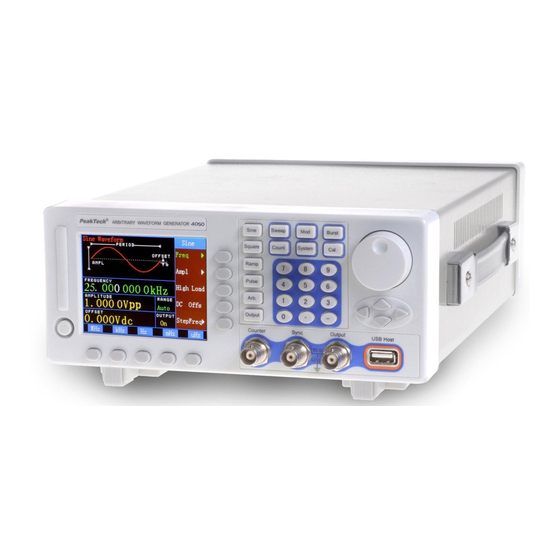
- Page 1 PeakTech 4035 ® operation manual DDS Function Generator -10-...
- Page 2 1. Safety Precautions This product complies with the requirements of the following European Community Directives: 89/336/EC (Electromagnetic Compatibility) and 73/23/EC (Low Voltage) as amended by 93/68/EC (CE-Marking). Overvoltage category III 1000V; pollution degree 2. CAT I: For signal level, telecommunication, electronic with small transient over voltage CAT II: For local level, appliances, main wall outlets, portable equipment...
- Page 3 * Do not conduct current measurements with the leads connected to the V/Ω-terminals of the equipment. * Check test leads and probes for faulty insulation or bare wires before connection to the equipment. * To avoid electric shock, do not operate this product in wet or damp conditions. Conduct measuring works only in dry clothing and rubber shoes, i.
-
Page 4: Chapter 1 Brief Introduction
Chapter 1 Brief introduction ® The front panel and rear panel of PeakTech 4035 DDS function generators is described in this chapter so as to help users to master the usage as quickly as possible. The main contents of the chapter are as follows. -
Page 5: Prepare To Use
1.1 Prepare to use To check the instrument and the accessories: 1.1.1 Check whether the instrument and the accessories are complete and unbroken. If the package is badly damaged, please keep it until the instrument passes the performance testing. 1.1.2 Plug in and turn on the function generator To guarantee the safe operation of the instrument, the following conditions should be achieved. - Page 6 Warning: In order to ensure the security of the operator, triple- core socket outlet with safe earth-wire must be used. 1.2 Description of Front Panel and Rear Panel Front panel 1.2.1 1.2.2 Rear panel...
-
Page 7: Screen Description
1.3 Screen description The following 5.7″TFT color LCD is used in the generator . Waveform display: The waveform of channel A is shown on the top left part ① of the front panel. ②Function Menu: The function menu is shown on the first line in the right display area. -
Page 8: Keyboard Description
1.4 Keyboard description There are 38 keys on the front panel, which are classified in five types. 1.4.1 Function keys The keys of (Tone)(Sweep)(AM/FM)(Burst)(Keying) are used to select 10 functions of the generator. The key of (Count)is used to select the function of frequency counting. The keys of (System)(Cal.) are used to set system information and to calibrate parameters. - Page 9 Adjusting of frequency of channel A: In order to adjust the frequency in detail or roughly, please press the key of (<) or (>)to move the white marker position and then rotate the knob to increase or decrease the number value in the marker position. Other selection data can also be adjusted by the knob so no more restatement here.
- Page 10 Setting of step frequency of channel A: Set the frequency step to be 12.5Hz. Firstly, press the key of (Option 5) and select “Step Freq”, and then press the keys of(1)(2)(•)(5) (Hz) in turn. Secondly, press the key of (Option 1) and select “CHA Freq”.
- Page 11 Setting of frequency step: Set the frequency step to be 200Hz. Press the key of (Option 1) and select “Step F”, and then press the keys of(2)(0)(0) (Hz) in turn. Setting of sweeping mode: Set the sweeping mode to be to-and-fro. Press the key of (Option 3) and select “U-D sweep”.
- Page 12 Setting of modulation waveform: Set the modulation waveform (it actually waveform of channel B) to be triangle waveform. Press the key of (Option 5) and select “Mod Shape”, and then press the keys of (2) (No.) in turn. 1.5.6 Amplitude modulation: Press the key of(AM/FM) and select the function of “Ampl Mod”.
- Page 13 Setting of amplitude of carrier wave: Set the amplitude of carrier wave to be 2Vpp. Press the key of (Option 2) and select “Carrier A”, and then press the keys of(2) (Vpp) in turn. Setting of hop frequency: Set the hop frequency to be 2Vpp. Press the key of (Option 3) and select “Hop Freq”, and then press the keys of(2) (kHz) in turn.
-
Page 14: Chapter 2 Principle Summarize
Amplitude modulation: 100% Burst counting: 3cycl Burst frequency: 100Hz Hop frequency: 5kHz Hop amplitude: 0Vpp Hop phase: 90° output: On Channel B : Waveform: sine frequency: 1kHz Amplitude: 1Vpp Carrier wave of channel A: 1times Output: On Chapter 2 Principle summarize In the present chapter, users will acquaint with the basic concept of the signal forming and the interior operation of the generator so as to know more about the specifications and use the generator in the best way. - Page 15 2.1 Principle frame Keyboard Displayer Knob Clock Digital circuit Modulation input Lowpass Comparator TTL output Amplitude Output Voltage Power control attenuation amplification amplification and AM 20-60dB Offset setting Output Output A protection Power Output B Amplitude Lowpass amplification control 2.2 Working principle of DDS To generate a voltage signal, the traditional analog signal source adopts electronic components as oscillator in different ways.
- Page 16 To generate a sine signal, for example, the function of y=sinx should be digitally quantized first, and then taking x as the address and y as the quantized data to store them into waveform memorizer. DDS uses phase adding technique to control the address of waveform memorizer. Add a phase increment on the present result of phase accumulator in each sampling clock period so as to change the output frequency value by change phase increment.
-
Page 17: Chapter 3 Handling Instruction
Chapter 3 Handling instruction In the present chapter, user can have a detail understanding of whole functions and usage of the generator so as to use the generator to solve the practical problems. General operation rule Frequency of channel A Frequency channel B Frequency sweeping Amplitude sweeping... - Page 18 3.1 General operation rule 3.1.1 Menu selection: There are Chinese or English menus available on the right of the screen, a triangle on the right of the menu means that there are multiple selections for the present menu. Press the same key to circularly select items of the menu.
- Page 19 3.1.3 Data input: If an item is selected, it will change to green which means the present parameter can be modified. Data are entered by 10 number keys writing from left to right. If entering more than one decimal point in a parameter, only the first decimal point is valid.
- Page 20 Press the key of (Option 5) and select “Step Freq”; press the keys of(1)(2)(.)(5)(kHz); press the key of (Option 1) and select “CHA Freq”; press the key of ( ) or ( ) sequentially. Now a series of increasing-by-distant or decreasing- by-distant frequencies are obtained in fast and accurate way.
- Page 21 3.2.3 Setting of amplitude of channel A: Press the key of (option 2) and select “CHA Ampl”. The present amplitude value will be changed to green. Then use the number keys or the knob to enter the amplitude value. The amplitude will be output at the end of “output A”.
- Page 22 3.2.5 Output load: The setting value of amplitude is calibrated when the output end is open. The real voltage of output load is the setting value of amplitude multiplied by the assignment ratio of load resistance and output resistance. The output resistance is about 50Ω.
- Page 23 If the selection of “attenuation of channel A” is fixed to 0dB, the output offset is equal to the set offset value, which is independent of amplitude. If the amplitude is set to 0V, the offset can be arbitrarily set within ±10V . The generator will become into a DC power source and the set DC voltage signal can be output.
- Page 24 Hereafter, press the key of (Option 5) , select “Recall”, enter recalling number and then press the key of (No.) , the specific parameters can be recalled. It will be much more convenient to use if storing the common-used parameter combinations. Select “recall parameters”...
- Page 25 3.3.3 Selection of waveform of channel B: Serial number is used to express the waveform of channel B. Press the key of (Option 3) and select “CHB Wform”. The present serial number will be changed to green. The serial number can be entered either by the number keys or by the knob.
- Page 26 It can be entered by the number keys or by the knob. The frequency of channel B will change simultaneously when the grade value is changed and the two values will be green then. If “CHA Harmo” is selected, the phases of the two channels can get the stable synchronously.
- Page 27 3.4 Frequency sweeping Pressing the key of (Sweep) and selecting the function of “frequency sweeping of channel A”, frequency sweeping signal can be output from the end of “output A”. The sweeping of output frequency adopts step mode. The output frequency will be added or subtracted automatically by a step every other interval time.
- Page 28 3.4.4 Setting of interval time: As the start frequency, end frequency and frequency step are settled, the interval time for each frequency step can be decided by the requirement of sweeping velocity. The shorter the interval, the faster the sweeping velocity.
-
Page 29: Frequency Modulation(Fm)
3.6 Frequency modulation(FM) Pressing the key of (AM/FM) and selecting “Freq Mod”, the signal of frequency modulation will be output from the end of “output A”. 3.6.1 Setting of carrier frequency: Pressing the key of (Option 1) and selecting “Carrie F”, the carrier frequency will be changed to green. The setting of carrier frequency can be carried by the number keys or adjusting of knob. -
Page 30: Amplitude Modulation(Am)
3.6.4 Setting of modulation waveform: Since the signal of channel B is taken as the modulation signal, the modulation waveform is, in fact, the waveform of channel B. Pressing the key of (Option 5) and selecting “Mod Shape”, the serial number of channel B will be changed to green. - Page 31 The two expressions are coincident virtually but the second is more clear and easy to be understood. In order to observe the amplitude clearly, the depth of amplitude modulation can be set much larger in the demonstration, even larger than 100%. But in practice, the depth value of amplitude modulation is under 50% in order that the modulation signal will not be distortion.
- Page 32 3.8.1 Setting of frequency of channel B: Signal of channel B is a burst output signal. The frequency and amplitude of channel B should be settled first. The setting method has been described in 3.3. 3.8.2 Setting of burst counting: Pressing the key of (Option 3) and selecting “Cycles”, the counting value of burst pulse series will be changed to green.
-
Page 33: Fsk Modulation
3.9 FSK modulation In digital communication and the system of remote control and remote measurement, the transmitting of digital signal usually use FSK or PSK, and the frequency or the phase of carrier wave is modulated by coding. The original digital signal is reverted via modulator in the receiver. -
Page 34: Psk Modulation
The difference between carrier amplitude and hop amplitude may be very large. Fixed attenuation of 0dB is used for channel A so as to avoid the frequent switch of relay in the auto mode. 3.10.3 Setting of interval time: Pressing the key of (Option 4) and selecting “Interval”, the interval time value will be changed to green. - Page 35 But since that the real interval time is not strictly equal to the carrier period, the waveform can only hold in short time. The closer the interval time and the carrier period, the longer the waveform. 3.12 Exterior Count Pressing the key of (Count) and selecting “Ext Count”, the interface of exterior measuring will be displayed.
- Page 36 Without “measuring resetting”, each result will be accumulated and displayed synchronously. So it is meaningless if the signal to be measured is continuous. 3.12.4 Setting of Gate time: Pressing the key of (Option 4) and selecting “Gate Time”, it will be changed to green. The gate time can be entered by the number keys or by the knob.
-
Page 37: System Setting
3.12.6 Measuring of exterior frequency: The signal of channel A is only used as the self-testing and demonstration of testing function. In practice, the measured signal is exterior signal. Press the key of (Option 1) , select “Ext Sourc”, and enter the measured exterior signal from the “Int Sourc”... -
Page 38: Parameter Calibration
Pressing the key of (Option 3) and selecting 3.13.3 Selection of interface: “Interface”, different programmable interfaces can be selected. The default selection is 0 and USB interface. 3.13.4 Programmable interface address: Pressing the key of (Option 3) and selecting “Prog Adds”, the programmable interface address will be changed to green. It can be settled by the keys or by the knob. - Page 39 The frequency of channel A will be changed until the accuracy is calibrated up to 10 . Because the synthesizer of channel B and the synthesizer of channel A use the same fixed clock reference, the frequency of channel B has the same accuracy as the frequency of channel A.
- Page 40 Calibrating state quits. The calibrating code is stored in non-losable memorizer so that they will not be lost even if the power is off. Unless calibrating again will the calibrating code be renewed. 3.15 Parameter calibration(2) The amplitude and offset cannot be calibrated via the keyboard. If the error is too big, the following calibrating method can be adopted.
-
Page 41: Chapter 4 Programmable Interface
Chapter 4 Programmable interface The usage of the programmable interface is introduced in this chapter. Using a cable wire, users can connect the generator with the computer via programmable interface to make up an automatic testing system that can be accomplished according to the pre-edited testing program. Interface application Interface selection USB interface... -
Page 42: Interface Application
4.1 Interface application Nowadays, computer is being widely used. Traditional measuring method is being replaced by digital one. Continuous manual measuring work has also been replaced by the auto-measuring controlled by computer, which is also a developing trend in the area of electronic measuring way. -
Page 43: Usb Interface
4.3 USB interface USB interface accords with the regulations of USB V1.1. 4.3.1 Interface down-wire: power wire: +5V, GND signal wire: D+, D- , bi-direction and tri-state. 4.3.2 Interface linking: Plug one end of the USB transmitting cable wire into the USB interface socket on the front panel and the other end into the USB interface socket on the computer. -
Page 44: Gpib Interface
If it isn’t from other machine, refuse to accept it and continue to wait the information from the current machine. If it is from the current machine, accept the data information until next address information, and judge again. 4.4.8 Data information: For the accepted data information, judge and save it. If the accepted charact er is change- line sign Chr(10), it can be considered that the data information has been accepted completely and the generator begins to operate according to the program. -
Page 45: Programming Commands
4.6 Programming commands Programming commands are a series of ASCII code character strings sent from computer to the controlled instrument via the interface. The controlled instrument works according to the commands. The programming commands of each instrument have its own format and definition. User should obey the regulation when programming to control the generator to accomplish the jobs. - Page 46 Table of option commands option command option command option command Frequency of AFREQ Interval INTVL channel A direction key Period of Start Down APERD STARA DOWN channel A amplitude direction key Amplitude of Stop AAMPL STOPA Parameter store STORE channel A amplitude Offset of Step...
-
Page 47: Application Program
Table of data commands data command data command Number 0 1 2 3 4 5 6 7 8 9 Decimal • point Minus Table of unit commands unit command unit command Frequency unit MHz kHz Hz mHz µHz Waveform number Amplitude unit Vrms mVrms Vpp mVpp Harmonic time... - Page 48 4.7.1 Entering into programmable state: The instrument will work in the manual state after startup. As soon as receiving the programmable command from the computer, the instrument will enter into the programmable state and there is a symbol “p” at the bottom left of the screen.
- Page 49 Point 3: According to the different physical variables, the generator gives different unit command. But different unit commands displayed in the same key position can be used in mixing. For example, the command AFREQ 120 Vpp looks unreasonable but it can be executed with correct result.
-
Page 50: Chapter 5 Introduction Of Optional Components
Example 7: Return to the local control state and get back to keyboard operating. The programmable command is : LOCAL Chapter 5 Introduction of Optional Components In the present chapter, other optional components except for standard are introduced. Frequency counter Power amplifier -53-... -
Page 51: Frequency Counter
5.1 Frequency counter: If user selects frequency counter, a frequency counter function board will be supplied in the package, whose input end will be connected to the socket of “input of exterior measuring” on the rear panel. The usage of the present optional component will be described in 3.12 in detail. 5.2 Power amplifier: If user selects power amplifier, a power amplifier board will be supplied in the package. -
Page 52: Chapter 6 Specifications
Chapter 6 Specifications Output characteristics of channel A Output characteristics of channel B Output characteristics of TTL General characteristics Characteristics of optional components -55-... - Page 53 6.1 Output characteristics of channel A 6.1.1 Waveform characteristics: Waveform types: sine, square, pulse, DC Waveform length: 3~16000 points Amplitude resolution: 10 bits Sampling rate: 180 MSa/s Harmonic distortion: ≥50dBc(<1MHz), ≥40dBc(1MHz~20MHz) ≥30dBc(20MHz~30MHz) Total distortion: ≤0.5%(20Hz~200kHz) Pulse, square: rise/fall time: ≤20ns over pulse: ≤...
- Page 54 6.1.6 Sweeping characteristics: linear frequency/amplitude sweeping Sweeping range: the start/end point can be set arbitrarily Sweeping step: any value greater than the resolution Sweeping rate: 10ms~60s/ step Sweeping mode: positive, negative, to-and-fro Manual sweeping: step/ time 6.1.7 Frequency modulation characteristics: Modulation signal: interior or exterior Offset of frequency modulation: 0%~20% 6.1.8 Amplitude modulation characteristics:...
-
Page 55: General Characteristics
6.2.4 Characteristics of harmonic wave: frequency of channel A is the harmonic of channel A Harmonic wave: 0.1~250.0 times Frequency of harmonic wave <1MHz Phase adjusting: 11.25°/step for rough adjusting 2°/step for fine adjusting 6.2.5 Burst characteristics: channel B as the burst output signal Frequency of channel B: 10mHz~1MHz Frequency of burst: 40mHz~500kHz Burst counting: 1~65000 periods... - Page 56 We herewith confirm, that the units are calibrated by the factory according to the specifications as per the technical specifications. We recommend to calibrate the unit again, after 1 year. ® © PeakTech 03/2008 EK/th -59-...
Need help?
Do you have a question about the 4035 and is the answer not in the manual?
Questions and answers