Table of Contents
Advertisement
Advertisement
Table of Contents

Subscribe to Our Youtube Channel
Related Manuals for Bay Tek Games DIZZY CHICKEN


Summary of Contents for Bay Tek Games DIZZY CHICKEN
-
Page 2: Factory Contact Information
FACTORY CONTACT INFORMATION BAY TEK GAMES INC. Pulaski Industrial Park 1077 East. Glenbrook Drive Pulaski, WI 54162 USA JOIN OUR SERVICE FIRST NETWORK! This free service is intended to keep you up to date on the latest game information, early notification of parts specials, pertinent technical bulletins, updates on retro fit parts, software upgrades, and much more. -
Page 3: Table Of Contents
FACTORY CONTACT INFORMATION ......2 WELCOME TO: DIZZY CHICKEN ........4 HOW TO PLAY . -
Page 4: Welcome To: Dizzy Chicken
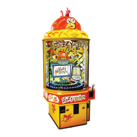
With a bright and colorful cabinet and fun game play that offers players a chance to win every time, Dizzy Chicken is sure to take your game room for a spin! Please take a moment to read through this manual and be sure to contact our factory if you have any questions, or would like some more information. -
Page 5: How To Play
HOW TO PLAY Give the ball a whack and watch it spin around the spiral. Land on any light to win tickets; Land on blue for 10 tickets. If the ball stops at purple, you get 20 tickets. orange light means 30. light is worth 100 tickets, plus a bonus shot! Hit the... -
Page 6: Specifications
GAME SPECIFICATIONS WEIGHT POWER REQUIREMENTS NET WEIGHT 450 LBS. INPUT VOLTAGE 100 to 120 220 to 240 RANGE SHIP WEIGHT 500 LBS. INPUT FREQUENCY 50 HZ 60 HZ DIMENSIONS RANGE WIDTH 45.25” MAX START UP OPERATING CURRENT CURRENT DEPTH 45.25” 2.2 AMPS @ 115 VAC 2.6 AMPS @ 115 VAC HEIGHT... -
Page 7: Height Modification Options
HEIGHT MODIFICATION OPTIONS... - Page 8 MARQUEE MODIFICATION GUIDE...
-
Page 9: Quick Set Up
QUICK SETUP GUIDE Place the game in its desired location. See height adjustment options on pages 7-8 if necessary. Using the bubble level on the playfield and the leveler feet, make sure the cabinet is as level as possible. Plug the power cable into a standard electrical outlet and turn the power switch inside the cabinet to the on position. -
Page 10: Dip Switch Settings
DIP SWITCH SETTINGS The dip switch bank is located on the mainboard, inside the front door of the game. *factory default settings are highlighted below SWITCH DESCRIPTION Analog Meter Units (games) (coins) Stored Credits/Tickets Owed (store) (clear) (on power cycle) not used not used... -
Page 11: Main Menu Functions
MAIN MENU FUNCTIONS Hold down the button inside the MENU front door of the cabinet for 2 seconds to open the main menu on the monitor. Press to scroll through the options, MENU SELECT to choose your settings. -
Page 12: Credits Per Game
CREDITS PER GAME Set the desired number of credits per game. The factory default is highlighted below. MASTER VOLUME Set the desired master volume. Neither game volume nor attract volume will exceed the master. The factory default is highlighted below. (off ) GAME VOLUME Set the desired game volume. -
Page 13: Fixed Ticket Payout
FIXED TICKET PAYOUT Setting this to any value but 0 will cause the game to pay out a set number of tickets for each game played. The factory default is highlighted below. (off ) GAME TIME-OUT When enabled, this function will cause the game to forfeit a player’s turn if they have not hit the ball in the allotted time. -
Page 14: Game Specific Options Menu
GAME-SPECIFIC OPTIONS BONUS ZONE LIGHT COUNT This setting adjusts how many red lights are in the “red light zone”. The factory default is highlighted below. BLUE TICKET VALUE This setting adjusts how many tickets are won when the ball lands on BLUE. The factory default is highlighted below. - Page 15 ORANGE TICKET VALUE This setting adjusts how many tickets are won when the ball lands on ORANGE. The factory default is highlighted below. 10 15 20 25 30 40 50 60 75 100 RED TICKET VALUE This setting adjusts how many tickets are won when the ball lands on RED. The factory default is highlighted below.
-
Page 16: Ticket Payout Settings
Once again, the factory defaults are highlighted in yellow in the table as well. When you decide to change a ticket pattern on your Dizzy Chicken game, please use the replacement display cut outs in the back of this manual to inform your customers of the ticket payout details. - Page 17 ALTERNATE TICKET PAYOUT SETTINGS 5 LIGHT 7 LIGHT 10 LIGHT AVG. TIX PATTERN PER GAME BONUS ZONE BONUS ZONE BONUS ZONE 1/2/4/20/100 2/3/5/8/100 1/2/4/8/100 BONUS VALUE 4/8/12/16/20 4/8/10/16/20 4/8/10/16/20 BONUS VALUE 8/10/15/30/50 6/8/15/30/50 6/8/15/20/50 10-13 BONUS 1000 VALUE 10/16/20/40/100 10/16/20/40/100 8/10/20/40/100 14-20 BONUS...
-
Page 18: Statistics
STATISTICS... -
Page 19: Diagnostics
DIAGNOSTICS SOLENOID (BALL RELEASE) Turning on the solenoid will release the ball into the launch position for testing purposes. SPIRAL COLOR TEST Turning on the spiral color test will cycle the colors of all playfield lights between red, green, blue and yellow. This will assist in locating any dim or burned out LEDs in the spiral. -
Page 20: Camera Menu
CAMERA MENU AUTO ALIGN CAMERA BEFORE CALIBRATING: be sure the ball is in the home position at the bottom of the spiral. Press the Select button twice to re-image the scoring camera. This process will take a minute or two. After completion of the calibration, verify that the ball position reads “0”. -
Page 21: Wiring Diagrams
MINIGEN BOARD PINOUT AACE1302 AACE1302 AACE1300 Left Side Ticket Right Side Ball Release Coil Ticket Dispenser Dispenser and Tilt AACE1302 Low Ticket Switches AACE1300 Speaker AACE1306 Comm to Playfield AACE1305 Egg Lights Comm to Motherboard A5CEAU010 Audio from AACE1303 Motherboard Black = Com White = Signal Red = +12VDC... - Page 22 COIN SWITCH/TICKET DISPENSER WIRING Left Ticket Dispenser Right Ticket Dispenser Ticket Tray Cable Ticket Tray Cable To Ticket Dispenser To Ticket Dispenser AACE3219 AACE3219 Part # A5TD1 Part # A5TD1 12 Volt Power 12 Volt Power Enable Signal Enable Signal Com Ground Com Ground Notch Signal...
- Page 23 BUTTONS, SPEAKERS, LIGHTS ETC. WIRING To next Playfield A5LI1300 Egg Light A5TI1001 13 Ohms across solenoid Tilt Plumb AACE1300 6 Volts DC when activated Ball Release Solenoid AACE1300 AACE1307 To 1st AACB2216 12 Volt Egg Light Spiral Power Translator Board To J24 Connector on Main Board AACE1300...
- Page 24 AC/ POWER SUPPLY WIRING Power to Egg Lights Power to Egg Lights Power to Egg Lights Power to Egg Lights AACB2216 under playfield under playfield under playfield under playfield Spiral AACE1319 AACE1319 AACE1319 AACE1319 Translator Board AACE1311 AACE1311 12 Volts DC under playfield LED strip under monitor AACE1317 Power Supply...
- Page 25 AC WIRING AC Bulb AC Bulb AC Bulb AC Bulb A5LI0001 A5LI0001 A5LI0001 A5LI0001 Important: All 4 lights must be on for camera to correctly locate red ball. AC Power to florescent lights AC Power to florescent lights AACE1314 AACE1314 Top lighting for game AC Bulb AC Bulb...
- Page 26 MOTHERBOARD COMMUNICATION WIRING A5CM3000 Camera A5CBxxxx USB Cable from Camera to Motherboard A5CORD23 10’ USB Male to Female Cable Connection AAMB7 A5CBxxxx VGA Cable from Motherboard to monitor A5CN1031 Adaptor to plug cable into Motherboard. AACE1306 Communication cable A5MO2200 from J2 on Interface Monitor Board to Motherboard AACB2204...
-
Page 27: Troubleshooting Guide
TROUBLESHOOTING GUIDE Troubleshooting Strategy Use common sense and a systematic method of troubleshooting to determine the exact problem, probable cause and remedy. Use the process of elimination to find the faulty component. Always check for the simple and obvious causes Troubleshooting Chart first such as unplugged, loose or broken wires and bad sensors, bent, pinched, stuck or jammed components. - Page 28 TROUBLESHOOTING GUIDE Problem Probable Cause Remedy Power cable unplugged from Ensure power is plugged into bottom of Monitor shows nothing monitor, down to power strip. at all on power on. monitor. Power strip faulty Peel marquee from right Change plug position, replace if needed bottom of monitor.
- Page 29 TROUBLESHOOTING GUIDE Problem Probable Cause Remedy Faulty power supply - Check for 12 Volts and green LED on motherboard. Monitor VGA cable unplugged. Monitor says “NO SIGNAL” for 5 seconds Faulty or loose RAM after power - Monitor Large power connector unplugged working.
- Page 30 TROUBLESHOOTING GUIDE Problem Probable Cause Remedy Monitor shows “No Boot De- Small clip-in hard drive is not being seen by computer. vice” on screen. Re-Boot game to see if problem still Push on spring clip and gently remove from motherboard. Re-install and power on game. exists.
- Page 31 TROUBLESHOOTING GUIDE Problem Probable Cause Remedy Blow dust from sensor and clean with Opto Sensor on ticket dispenser dirty. isopropyl alcohol. Replace with working dispenser to isolate the Faulty ticket dispenser. Tickets on problem. (A5TD1) monitor does Flip tickets and load upside-down to have large Tickets do not match Notch on tickets cut too...
- Page 32 TROUBLESHOOTING GUIDE Problem Probable Cause Remedy All Playfield Lights are spiraling differ- Faulty cable. Discon- Check large phone cable from MiniGen board, through nected, loose or broken Spiral Translator Board up to one egg in the spiral. ent colors. wires. Check for continuity.
- Page 33 TROUBLESHOOTING GUIDE Problem Probable Cause Remedy Game not level and is tipping. Use leg levers on bottom of game to adjust level Tilt Alarm going off of game. too often. Lower or raise Plumb Bob so that the center is Plumb Bob is not adjusted properly.
- Page 34 TROUBLESHOOTING GUIDE Problem Probable Cause Remedy Game Meter does not Ensure Dipswitch # 1 on Minigen board is set Meter may be counting coins work. instead of games. to ON. Game meter can be set to coin meter on dip- Disconnected, loose or broken Check connections and reseat J22 on main wires.
-
Page 35: Power Supply Diagnostics
POWER SUPPLY DIAGNOSTICS 1.) Verify AC power to game. Check power strip in front door. The rocker switch should be illuminated. 3.) Check connection to power supply. 4.) Ensure Power Supply switch is set to 115V (or 230V) (Some model power supplies may not have this) 5.) Ensure Power switch is on. -
Page 36: Bill Acceptor Diagnostics
NOTICE: INSTALLING A BILL ACCEPTOR VOIDS ETL CERTIFICATION AND CE COMPLIANCE The Dizzy Chicken Game does not come standard with a Bill Acceptor. If you would like to add one to your game, please order AACE4626 & A5PL4201 (Mounting Plate) If you would like to install DBA. -
Page 37: How To: Access Ball Release
HOW TO: ACCESS BALL RELEASE Step 1: Step 4: Power game off. Remove the 2 bumpers that are located by the red ball. Remove grey phone cable labeled CE1313 from mini gen main board. Step 5: Step 2: Remove the red ball from the track. Remove black and red cable labeled Remove the 4 square head screws in the front of the CE1311 from power supply cable. -
Page 38: How To: Recalibrate Camera
HOW TO: RECALIBRATE CAMERA The camera will need to be recalibrated if new software is installed in game or if the game has been handled roughly and camera has shifted position. Step 1: Verify all lights are ON inside cabinet. (4 up top, 2 strips along sides, 1 strip under monitor) Enter menu and go to Camera Diagnostics Use menu buttons to enter menu and go to this screen: Step 2: Select “New Base Image”... -
Page 39: Parts Pictures
PARTS PICTURES AACBL4A-DOOR-DC AACE1300 AACE1301 AACE1302 AACE1303 AAPB1309 AACE1311 AACE1306 AACE1307 AACE1308 AACE8868 AAPB2700 AACE8811 AACO1000 A5CEAU010 AACE3219 A5BA1301 A5CE6601 A5CM-COMP AASW200 A5CN1031 A5CORD23 A5CORD5 A5EB9000 A5FI9010 AABA1300 A5PS1008 A5LI1300 A5TD1 A5TI1001 A5LK2000 A5LK5001 AACB2204 AAMB7-HD AANEWGEN1-PJ... - Page 40 PARTS PICTURES (DECALS) A5DE1300 A5DE1301 A5DE1302 A5DE1303 A5DE1304 A5DE1305 A5DE1306 A5DE1307 A5DE1308 A5DE1309 A5DE1310 A5DE1311 A5DE1312 A5DE1313 A5DE1314 A5DE1315 A5DE1316 A5DE1317 A5DE1318 A5DE1319 A5DE1320 A5DE1321 A5DE1322 A5DE1323 A5DE1325 A5DE1326 A5DE1327 A5DE1328 A5DE1329...
- Page 41 PARTS PICTURES A5DE1330 A5DE1331 A5DE1332 A5DE1333 A5DE1334 A5DE1345 AACH1300 AAHA1300 AALE1300 AASO1300 AAVF1300 AACB2216 AABW1300...
-
Page 42: Decal Identification
DECAL IDENTIFICATION A5DE1300_DC_FaceSet A5DE1302_DC_WingRight A5DE1301_DC_WingLeft A5DE1328_DC_BTGlogo A5DE1303_DC_FeathersLeft A5DE1305_DC_DizzyChicken A5DE1304_DC_FeathersRight A5DE1306_DC_PerchLeft A5DE1308_DC_PerchFront A5DE1309_DC_wallLeft A5DE1307_DC_PerchRight A5DE1310_DC_wallMidLeft A5DE1311_DC_wallMiddle A5DE1312_DC_wallMidRight A5DE1313_DC_wallRight A5DE1340-A5DE1346 A5DE1318_DC_TicketBucket Perch Bonus Replace A5DE1333_DC_AimForGreen A5DE1314_DC_Monitor A5DE1329_DC_KickerLeft A5DE1330_DC_KickerRight A5DE1315_DC_SpiralCenter A5DE1317_DC_Arrow A5DE1332_DC_TooDizzy A5DE1331_DC_WhackerInstruct A5DE1316_DC_Spiral A5DE1323_DC_ApronRight A5DE1319_DC_ApronLeft A5DE1322_DC_ApronHandle A5DE1320_DC_ApronCorner A5DE1321_DC_ApronFront A5DE1324_DC_CabinetSide A5DE1327_DC_CabinetSpeaker A5DE1325_DC_CabinetFront A5DE1326_DC_CabinetBottom A5DE1334_DC_CabinetDoor... -
Page 43: Circuit Board Pinouts
MAINBOARD PINOUT ... - Page 44 MAINBOARD PINOUT GUIDE...
- Page 45 MAINBOARD PINOUT GUIDE...
-
Page 46: Maintenance Log
MAINTENANCE LOG If repairs are necessary, it is good practice to keep a log of repairs done and parts ordered. The chart below will assist you in tracking your game’s maintenance. DATE MAINTENANCE PERFORMED PARTS ORDERED INITIALS... -
Page 47: Technical Support
Bay Tek games. Many of our games share the same main-board electronics. This means you can buy one set of spare electronics to support many of your Bay Tek games. Spare boards allow you to get your game up and running the quickest and provide you a valuable troubleshooting option. Call our... -
Page 48: Warranty
WARRANTY Bay Tek Games warrants to the original purchaser that all game components will be free of defects in workmanship and materials for a period of 6 months from the date of purchase. If you fill out the registration card in the cashbox of the game, Bay Tek will add another 3 months to your warranty, free of charge. -
Page 49: Replacement Ticket Value Graphics
TixPat A5: 1/2/4/20/100 NO BONUS (Bonus Zone= 5 lights) Average Tix: (3-4) TixPat A7: 2/3/5/8/100 NO BONUS (Bonus Zone= 7 lights) Average Tix: (3-4) TixPat A10: 1/2/4/8/100 NO BONUS (Bonus Zone= 10 lights) Average Tix: (3-4) - Page 51 TixPat B5: 4/8/12/16/20 BONUS: 500 (Bonus Zone= 5 lights) Average Tix: (6-9) TixPat B7: 4/8/10/16/20 BONUS: 100 (Bonus Zone= 7 lights) Average Tix: (6-9) TixPat B10: 4/8/10/16/20 BONUS: 50 (Bonus Zone= 10 lights) Average Tix: (6-9)
- Page 53 TixPat C5: 8/10/15/30/50 BONUS: 1000 (Bonus Zone= 5 lights) Average Tix: (10-13) TixPat C7: 6/8/15/30/50 BONUS: 500 (Bonus Zone= 7 lights) Average Tix: (10-13) TixPat C10: 6/8/15/20/50 BONUS: 100 (Bonus Zone= 10 lights) Average Tix: (10-13)
- Page 55 TixPat D5: 10/16/20/40/100 BONUS: 2500 (Bonus Zone= 5 lights) Average Tix: (14-20) TixPat D7: 10/16/20/40/100 BONUS: 1000 (Bonus Zone= 7 lights) Average Tix: (14-20) TixPat D10: 8/10/20/40/100 BONUS: 500 (Bonus Zone= 10 lights) Average Tix: (14-20)
- Page 57 TixPat E5: 10/20/30/50/500 BONUS: 2500 (Bonus Zone= 5 lights) Average Tix: (24-28) TixPat E7: 10/20/30/50/500 BONUS: 1000 (Bonus Zone= 7 lights) Average Tix: (24-28) TixPat E10: 10/2030/50/250 BONUS: 500 (Bonus Zone= 10 lights) Average Tix: (24-28)
- Page 59 TixPat F5: 10/20/50/100/500 BONUS: 5000 (Bonus Zone= 5 lights) Average Tix: (30-36) TixPat F7: 10/20/30/100/500 BONUS: 2500 (Bonus Zone= 7 lights) Average Tix: (30-36) TixPat F10: 10/20/40/50/500 BONUS: 1000 (Bonus Zone= 10 lights) Average Tix: (30-36)
- Page 61 TixPat G5: 10/20/40/500/1000 BONUS: 5000 (Bonus Zone= 5 lights) Average Tix: (48-54) TixPat G7: 10/20/50/200/1000 BONUS: 2500 (Bonus Zone= 7 lights) Average Tix: (48-54) TixPat G10: 10/30/50/150/500 BONUS: 1000 (Bonus Zone= 10 lights) Average Tix: (48-54)
- Page 63 TixPat H5: 10/30/100/500/1000 BONUS: 5000 (Bonus Zone= 5 lights) Average Tix: (60-66) TixPat H7: 10/30/100/250/1000 BONUS:2500 (Bonus Zone= 7 lights) Average Tix: (60-66) TixPat H10: 20/30/100/200/500 BONUS: 1000 (Bonus Zone= 10 lights) Average Tix: (60-66)
- Page 65 TixPat I5: 10/20/30/40/100 BONUS: 800 (Bonus Zone= 5 lights) Average Tix: (14-20) TixPat I7: 6/20/30/40/100 BONUS: 800 (Bonus Zone= 7 lights) Average Tix: (14-20) TixPat I10: 4/10/20/50/100 BONUS: 800 (Bonus Zone= 10 lights) Average Tix: (14-20)
Need help?
Do you have a question about the DIZZY CHICKEN and is the answer not in the manual?
Questions and answers