Table of Contents
Advertisement
Advertisement
Table of Contents
Troubleshooting

Related Manuals for Bay Tek Games Quick Drop


Summary of Contents for Bay Tek Games Quick Drop
-
Page 2: Factory Contact Information
FACTORY CONTACT INFORMATION BAY TEK GAMES INC. Pulaski Industrial Park 1077 East. Glenbrook Drive Pulaski, WI 54162 USA JOIN OUR SERVICE FIRST NETWORK! This free service is intended to keep you up to date on the latest game information, early notification of parts specials, pertinent technical bulletins, updates on retro fit parts, software upgrades, and much more. -
Page 3: Table Of Contents
TABLE OF CONTENTS FACTORY CONTACT INFORMATION ......2 WELCOME TO: Quik Drop ........4 HOW TO PLAY . -
Page 4: Welcome To: Quik Drop
Your Friends at Bay Tek Games GAME INSPECTION Inspect the game for any damaged, loose, or missing parts. If damage is found, please contact your freight carrier first. Then, contact Bay Tek Games’ Service Department at 920.822.3951 or e-mail them at service@baytekgames.com for further assistance. -
Page 5: How To Play
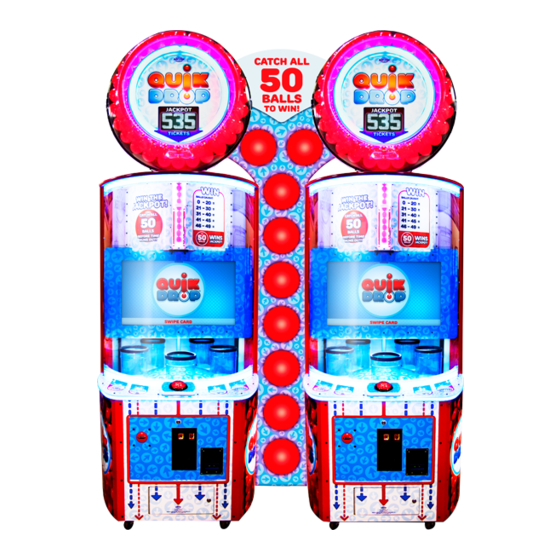
HOW TO PLAY Press the button to drop 50 balls into the moving buckets before time runs out. Rapid fire is encouraged! Win tickets for balls caught. Catch all 50 balls in the allotted time to win the progressive Jackpot! -
Page 6: Game Specifications
GAME SPECIFICATIONS WEIGHT POWER REQUIREMENTS NET WEIGHT 600 LBS. INPUT VOLTAGE 100 to 220 to RANGE 120 VAC 240 VAC SHIP WEIGHT 700 LBS. INPUT FREQUEN- DIMENSIONS 50 HZ 60 HZ CY RANGE WIDTH 38.5” MAX OPERATING DEPTH 44” CURRENT 109”... -
Page 7: Setup Guide
SETUP GUIDE Remove back door of cabinet. Place the marquee assembly on the top of the cabinet, lining up the tube so it drops into the white plastic ring. The marquee is heavy and awkward- please seek assistance! Make sure the cables are routed through the hole in the top, and secure marquee in place with four included 9/16”... - Page 8 SETUP GUIDE Plug in the cables from the marquee to the color-coded cables inside the cabinet as shown. There should be a total of 7 connections made: DISPLAY COMM. RIBBON RED LIGHTS BALL SENSOR SPEAKER AUGER MOTOR WHITE LIGHTS MARQUEE POWER Replace the back door and lock.
-
Page 9: Main Menu
MAIN MENU Press and hold the MENU button located inside the front door to access the Main Menu. Scroll through the options with the MENU button. Make your selections with the MENU SELECT button. MAIN MENU OPTIONS MUTE OPTION ENABLED DISABLED GAME VOLUME ATTRACT VOLUME... -
Page 10: Game Menu
GAME MENU GAME MENU OPTIONS TIME PER GAME 20 SEC. 30 SEC. DEFAULT: 22 SEC. (INC. 1 SEC) MAX TIME Game time is extended minutely 20 SEC. 30 SEC. DEFAULT: 30 SEC. with each non-jackpot win game (INC. 1 SEC) played to decrease difficulty ATTRACT BALL DROP 0 (OFF) -
Page 11: Payout Menu
PAYOUT MENU PAYOUT MENU OPTIONS CREDITS PER GAME FREE PLAY CARD READER FALSE TRUE Changes “Credits 0/4” to “Swipe Card” DIVIDE TICKETS BY 2* FALSE TRUE JACKPOT START 1000 DEFAULT: 500 (INC 50) JACKPOT MAX 1000 DEFAULT: 1000 (INC 50) JACKPOT INCREMENT JACKPOT RESET Press MENU SELECT button 3 times to reset jackpot to start... -
Page 12: Ticket Buckets
TICKET BUCKETS Factory defaults are highlighted below. TICKET BUCKET OPTIONS AVERAGE TICKETS PER GAME BALLS CAUGHT 10-14 14-17 18-23 25-30 28-32 33-36 48-54 66-72 HIGH TICKET VALUES 50 (JACKPOT) Jackpot is Progressive; this setting represents start point *The high end range of balls caught in each ticket bucket is adjustable in the menu, and will automatically populate the low end value for the following bucket to avoid overlap. -
Page 13: Statistics
STATISTICS STATISTICS Total Games Played Number of games played since last Reset Total Payout Number of tickets payed out since last Reset Total Jackpots Won Number of times Jackpot has been won since last Reset Jackpot Payout Number of Jackpot tickets payed out Average Payout Total average tickets payed out per game Reset Statistics... -
Page 14: Diagnostics
DIAGNOSTICS MENU DIAGNOSTICS MENU Motor RPM; will increase as motor CAROUSEL Displays ON when the player button BUTTON INPUT wears to keep constant carousel is pressed down MOTOR speed (approx. 9.9 sec rotation) Forward/Reverse; runs forward in TOP FEED ON when ball tube is detected as normal operation, if a jam occurs, TUBE SENSOR full;... -
Page 15: Error Codes
ERROR CODES Quik Drop is equipped with error-sensing software. When the Game Error screen appears, the game will not function normally. ERROR CODES (shown in bottom left corner of the screen) COMMUNICATION ERROR Lost communication to the micro-controler BUTTON STUCK Ball drop button has been “ON”... -
Page 16: Error Codes
ERROR CODES; SENSOR LOCATIONS TOP AUGER MOTOR ENCODER SENSOR SENSOR LOCATION DIAGRAM BALL TUBE FILL SENSOR CAROUSEL MOTOR BALL COUNT ENCODER SENSOR SENSOR BALL SCORE SENSOR... -
Page 17: How To: Access Ball Hopper
HOW TO: ACCESS BALL HOPPER Release the latches on the right side of the marquee face and swing it open. This provides access to the ball hopper, auger, and sensor. HOW TO: ADJUST MARQUEE HEIGHT Each side of the marquee support is equipped with a height adjustment system, allowing flexibility in maximum height from 109”... -
Page 18: How To: Replace Carousel Motor
HOW TO: REPLACE CAROUSEL MOTOR If just replacing the motor: Turn game off, remove the guard Remove motor bracket by unbolting the 4 bolts holding it on. Remove sprocket with 1/8th inch allen wrench and 4 screws holding motor in place. - Page 19 HOW TO: REPLACE CAROUSEL MOTOR Replace with new motor and sprocket goes on flush with the shaft of the motor with 1/8th inch allen wrench. When you bolt the motor back into the game, before you tighten it down, make sure the chain is not too tight or too loose.
-
Page 20: Circuit Board Pinouts
PIN OUT GUIDE MINIGEN 3‐PIN CONNECTOR BOTTOM BALL SENSOR TOP COIN DOOR 3‐PIN CONNECTOR BALL SENSOR MENU SELECT AACB3906 AND COUNTERS TO TICKET DISP. TO DBA CAROUSEL MOTOR TO CAROSEL MO‐ TOR SENSOR BALL SOLENIOD AC DRIVER BOARD PLAY‐ FIELD LIGHTS BUTTON 12V IN FROM POWER SUPPLY TO SPEAKERS ... -
Page 21: Wiring Diagrams
WIRING DIAGRAMS MOTHERBOARD COMMUNICATION RX is receiver communication from Newgen Board. It should be flashing rapidly and dim. TX is transmitter communication from Motherboard. It should be flashing rapidly and dim. Power comes from Newgen Board. AACE5524 LED should be on if power is on. Communication cable from blue J16 on Newgen board to J1... - Page 22 WIRING DIAGRAMS AC/12 VOLTS FROM POWER SUPPLY Right Instruction Playfield Left Instruction LED lighting Illumination LED lighting AACB3906 Motor Driver Board + ‐ + ‐ + ‐ AAMB9A-HD AACE5840 AACE5840 AACE5808 AACE5852 AACE5812 AACE5329 Power Cable to SATA Hard Drive A5HD1800 SATA Hard Drive AACE5838 To Marquee...
- Page 23 WIRING DIAGRAMS JACKPOT DISPLAY, SPEAKER, CAROUSEL MOTOR & BALL DROP SOLENOID A5LD1058 Jackpot Display AACE5841 A5MO5800 AACE???? Carousel Motor 1.2 Ohms AACB3904 Ground AACE5855 Wire Spli�er Board AACE3454 5 Amp Fuse (A5FUSE11) AACE5823 3.5 Amp Fuse (A5FUFB010) AACE5843 AACE5842 AASO5800 5 Volts from Ball Drop Power Supply Solenoid...
- Page 24 WIRING DIAGRAMS SENSORS & BALL DISPENSE AUGER MOTOR AAMO5801 12 Volts DC power between the Red and Black wires. Ball Dispense Motor Normally a ball is blocking sensor and has 0 VDC AACB3404 between Black and white wires (LED is ON) 2.4 Ohms Ball Tube Sensor ...
- Page 25 WIRING DIAGRAMS COUNTERS, MENU BUTTONS, BALL DROP BUTTON, FEED SENSOR & BLOWER Ticket Counter AACO3320 Game Counter AAPB2700 Menu To J25 Button connector AACE5820 AAPB2700 Menu Select AANEWGEN1-PJ/RBN 12 Volts DC power between the Black and Red wires. When Blocked - 0 VDC between the Black and White wires.
- Page 26 WIRING DIAGRAMS MARQUEE LIGHTING, COIN MECH & TICKET DISPENSERS AACE5848 LED’s in the back of Marquee AACE5818 Ticket Switch AACE5849 AACE5822 LED’s around AACE5830 back of Marquee AACE5850 LED’s around These con- side of Marquee nectors are To J21 colored Blue Connector AACE5838 This ICL connector...
-
Page 27: Debit Card System Installation
WIRING DIAGRAMS DEBIT CARD SYSTEM SETUP Option #1: New card swipe systems may come with a standard 9 pin Molex connector. Simply unplug this connector and plug into your card swipe reader. AACE2801 AACE2801 Option #2: If your card swipe systems does not have a standard 9 pin Molex connector, then you will have to splice wires into the AACE2801 harness. -
Page 28: Updating Software
NOTE: The file will load quickly; you will notice that the USB stick will flash, and the game will return to normal operating condition. If you have any questions or need further assistance please contact Bay Tek Games at 920-822-3951 ext. 1102... -
Page 29: Troubleshooting Guide
TROUBLESHOOTING GUIDE No power to the game Check wall outlet No lights Reset powerstrip breaker switch or building Circuit breaker Change plug loca�on, replace if needed Bill Acceptor powers on. Make sure rocker switch is set ON. (‐) and switch at 100V or 230V But everything else off. See power supply diagnos�cs to isolate bad compo‐ (Power Supply not ON) nent. A bad motor or 12 volt short would cause this. Game not coining up Check coin switches—both should be wired nor‐ mally open. If one switch is “closed” the other will not work either. Check wiring to mini gen board. Check Pay In/Out Menu. Ensure Credits per Game is set. Default = 4 No sound Enter Main Menu and verify: Game Volume & A�ract Volume are not zero Motherboard creates sound, Mini Gen board Check connec�ons and reseat audio cable from amplies it. motherboard to Mini Gen bard Unplug audio jack cable (A5CEAU010) from moth‐ erboard, plug into MP3 player and see if music is amplied and comes out of speaker. If Yes ‐ then motherboard is faulty. If No ‐ then Mini Gen board may be faulty. Replace speaker. AACE8811 ... - Page 30 TROUBLESHOOTING GUIDE Tickets do not dispense or Wrong amount Opto Sensor on �cket dispenser dirty. dispensed. Faulty �cket dispenser. Notch on �ckets cut too shallow. Faulty cable. Disconnected, loose or broken wires. Faulty Mini Gen Board. Se�ngs in Menu are incorrect. Low Tickets message on monitor Tickets are empty in �cket tray The number of �ckets le� to dispense will also Faulty cable. Disconnected, loose or show broken wires. Faulty low �cket switch. Faulty Mini Gen Board No Communica�on between boards. Check green LED’s on Serial Interface board. Game does not coin up “Power” solid ON “TX” & “RX” blinking very fast, If “TX” & “RX” are not blinking very fast Communica�on to Motherboard faulty. Check AACE5523 to motherboard. Check or replace adaptor (A5CN1031) Replace Serial Interface board. (AACB2204) Game Meter does not work Verify meter does not click at end of game Disconnected, loose or broken wires. Check connec�ons and reseat Count/Menu on Mini Gen board Faulty counters. Faulty Mini Gen Board ...
- Page 31 TROUBLESHOOTING GUIDE Menu Bu�ons do not work. Disconnected, loose or broken wires. Faulty bu�on. Faulty communica�on between motherboard and Mini gen. Monitor shows “No Signal” Faulty power supply ‐ Check for 12 Volts and blink‐ ing green LED on SATA Drive Monitor cable unplugged Faulty or loose RAM Power game down, wait 10 seconds, then power...
-
Page 32: Troubleshooting Guide
TROUBLESHOOTING GUIDE Monitor shows “Kernel panic‐unable to mount Faulty or loose RAM root” on screen. Ball jam in auger Ball sensor on tube not func�oning properly Check voltage (should be 3.2 coming from the Sensor) Cabinet Ligh�ng does not work. 12 Volt White LED’s There are 2 different types of cabinet ligh�ng Faulty cable. 12 Volt White LED’s & Disconnected, loose or broken wires. Individual LED strip out Colored LED’s that change color Colored LED’s , Faulty cable. Disconnected, loose or broken wires. Individual LED strip out En�re sec�on of LED’s do not work, Specic Colors do not light on all LED strips ... -
Page 33: Power Supply Diagnostics
POWER SUPPLY DIAGNOSTICS Verify AC power to game. 1.)Check power strip in front door. The rocker switch should be illuminated. 2.) Check connec�on to power supply. 3.) Ensure Power Supply switch is set to 115V (or 230V) (Some model power supplies may not have this) 4.) Ensure Power switch is on. 5.) Ensure fan is turning. ‐ If power supply fan is turning and there is no 12 Volt out, then replace power supply. (AAPS1008‐GB) ‐ If power supply fan is not turning, then con�nue to “Verify Power to Motherboard” Verify Power to Motherboard The motherboard will turn on power supply. If your game has no 12 volts, it may be the motherboard not turning on. In addi�on ‐ there may be a 12 volt short somewhere else in cabinet that is not allowing the power supply to turn on. Minimize load on power supply and isolate short Unplug all outputs from power supply except for motherboard. This will have power supply, motherboard, and monitor le� plugged in. If power supply, motherboard, and monitor now turn on: Plug in one component at a �me to power supply to locate short. If power supply s�ll does not power on, then con�nue to steps 1,2, and 3. ... -
Page 34: Parts List
PARTS LIST PART # DESCRIPTION PART # DESCRIPTION A5ME5817 Metal Ball Counting Bracket A5BA3200 Red Balls (70 Per Game) A5BA5801 Top Marquee Red Balls,54 per game A5ME5818 Metal Sensor Bracket A5CN1031 Connector Adapter A5ME5820 Metal Encoder Sensor Bracket A5CB1499 Cash Box A5ME5821 Metal Top Encoder Bracket AATU5800... -
Page 35: Parts List
Carousel Motor Fuse Cable AACB4401 Carousel Home Sensor AAPB2700 Push Button Assembly AABD5029-A AC Driver Board With Fuses AACE8811 Speaker Assembly AANEWGEN1-PJ/RBN Mini Gen Main Board, Quick Drop AABL3201 Blower Assembly AAMB9A-HD Mother Board A5TD1 Ticket Dispenser AASO5800 Solenoid Assembly... -
Page 36: Parts Identification
PARTS IDENTIFICATION A5LK5002 A5PL8900 AASW200 A5TD1 A5TT4000 AABK1013 AACB4401 AACBL4A‐DOOR AACE5523 AACE5524 AACE5844 AACE5845 AACE5846 AACE5847 AACE5848 AACE5849 AACE5850 AACE8811 AACO3320 AAMB8A‐HD AABD5029‐A AACB2204 ... - Page 37 PARTS IDENTIFICATION A5BA3200 A5BR1001 A5CB1499 A5CEAU010 A5CN1031 A5CO4203 A5DE0042 A5DE5800 A5DE5801 A5DE5802 A5DE5803 A5DE5804 A5DE5805 A5DE5806 A5DE5808 A5DE5809 A5DE5810 A5DE5811 A5DE5812 A5DE5813 A5DE5814 A5DE5815 A5DE5816 A5DE5817 ...
- Page 38 A5DE5809_CABINET SIDE LEFT A5DE5810_CABINET SIDE RIGHT A5DE5806_MONITOR COVER AVAILABLE BUT NOT PICTURED: A5DE5816_CUSTOM SCORE SET A5DE5817_CUSTOM TICKET SET A5DE5813_WHEEL RAMP A5DE5801_CONTROL PANEL A5DE5800_BUTTON PLATFORM A5DE5802_CABINET FRONT A5DE5803_MECH DOOR A5DE5805_SIDE PANEL (2/GAME) A5DE5804_COIN DOOR QUIK DROP © 2015 BAY TEK GAMES, INC.
-
Page 39: Maintenance Log
MAINTENANCE LOG If repairs are necessary, it is good practice to keep a log of repairs done and parts ordered. The chart below will assist you in tracking your game’s maintenance. DATE MAINTENANCE PERFORMED PARTS ORDERED INITIALS... -
Page 40: Technical Support
Bay Tek games. Many of our games share the same main-board electronics. This means you can buy one set of spare electronics to support many of your Bay Tek games. Spare boards allow you to get your game up and running the quickest and provide you a valuable troubleshooting option. Call our... -
Page 41: Warranty
WARRANTY Bay Tek Games warrants to the original purchaser that all game components will be free of defects in workmanship and materials for a period of 6 months from the date of purchase. If you fill out the registration card in the cashbox of the game, Bay Tek will add another 3 months to your warranty, free of charge.
Need help?
Do you have a question about the Quick Drop and is the answer not in the manual?
Questions and answers