Advertisement
Quick Links
Thank you for purchasing a Sealey product. Manufactured to a high standard this product will, if used according to these instructions
and properly maintained, give you years of trouble free performance.
IMPORTANT: PLEASE READ THESE INSTRUCTIONS CAREFULLY. NOTE THE SAFE OPERATIONAL REQUIREMENTS, WARNINGS AND CAUTIONS.
USE THIS PRODUCT CORRECTLY AND ONLY FOR ITS INTENDED PURPOSE. FAILURE TO DO SO MAY CAUSE DAMAGE
AND/OR PERSONAL INJURY AND WILL INVALIDATE THE WARRANTY. RETAIN THESE INSTRUCTIONS FOR FUTURE USE.
1.
SAFETY INSTRUCTIONS
3 Maintain the pump in good condition (use an authorised service agent).
3 Replace or repair damaged parts. Use recommended parts only. Non authorised parts may be dangerous and will invalidate the warranty.
3 Keep the pump clean for best and safest performance.
3 Ensure the power supply (vehicle battery) corresponds with the requirements of the pump. TP98 12Volt, TP9824 24Volt DC power supply.
3 Ensure that there is more liquid in the suction tank than will be pumped.
3 Ensure that the capacity of the receiving tank is sufficient to hold the pumped fuel.
3 Wear safety goggles and gloves, and protective clothing when working around fuel. A full range of personal safety equipment is available
from your local Sealey dealer.
3 Use the pump in an appropriate working area for its function. Keep area clean and tidy and free from unrelated materials, and ensure
there is adequate lighting.
3 Maintain correct balance and footing. Ensure the floor is not slippery and wear non slip shoes.
3 Keep children and unauthorised persons away from the working area.
8 DO NOT ‘dry run’ the pump without fuel. This will damage the pump’s internal components and will invalidate your warranty.
8 DO NOT operate the pump continuously for more than 30 minutes. The duty cycle of the unit is 30 minutes, after which the motor must
be left to cool down.
8 DO NOT run the unit for more than 2-3 minutes with the delivery nozzle closed.
8 DO NOT start or stop the pump by connecting or disconnecting the battery clamps.
8 DO NOT operate the pump with wet hands.
8 DO NOT use the pump where explosive or flammable vapours may be present.
8 DO NOT tamper with the pump connections.
p WARNING! DO NOT use the unit to pump the following fluids:
Petrol, flammable liquids with PM <55°C, water, alimentary liquids with viscosity >20 cSt., corrosive chemicals and solvents.
2
INTRODUCTION
.
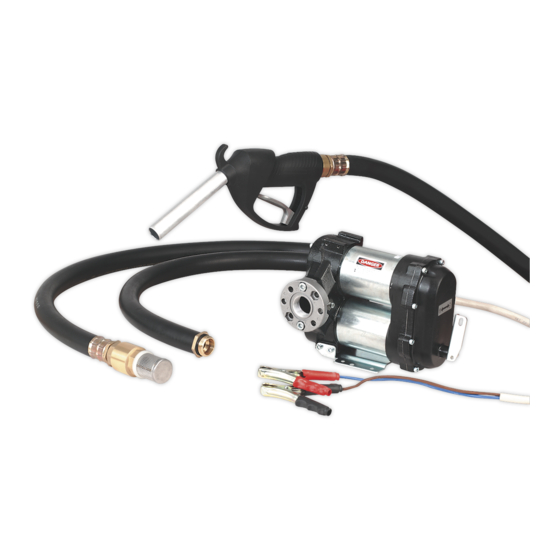
Electric 12 or 24Volt pump kit with battery clips. High flow pump unit with bypass valve, suitable for filling diesel vehicles on site. Cast iron pump
body with anti-corrosion finish. Includes integrated on/off switch, delivery hose with manual delivery nozzle, suction hose and filter.
3.
PREPARATION & ASSEMBLY
p WARNING Conical fittings should not be used to connect to the inlet/outlet ports as they will damage the seats on the pump casing.
3.1. Before using the pump, unpack all materials and inspect the pump unit for damage.
3.2. Connect the unit to appropriate voltage battery and ensure the motor will run up freely, this can be done before connecting hoses.
3.3
Attach the two flanges supplied to the inlet and outlet ports of the pump using the socket cap bolts provided. The flanges have different
recesses for different types of fixings in either face. Insert the socket cap bolts into the circular counterbored recesses you will find in one
face of each flange. Ensure that the ‘O’ rings provided are trapped in the groove in the flange face which seals onto each port.
3.4
A mounting bracket is supplied which can be attached to either side of the inlet/outlet casting. The pump can be mounted in either a
horizontal or a vertical axis. Ensure that the pump is mounted so that the on/off lever is visible and readily accessible.
3.5
The delivery/outlet hose and suction/inlet hose are supplied with a male threaded fitting at either end.
3.6
Attach the filter to one end off the suction hose. Identify the inlet port by means of the flow arrows shown on the cast body of the unit
adjacent to each port and then attach the hose to the inlet port.
3.7
Attach the delivery nozzle to one end of the outlet hose. Before the delivery hose can be attached to the outlet port the pump body must
be partially filled with diesel fuel to aid the priming process. (See next section.)
4.
USING THE APPLIANCE
WARNING! Check to ensure you are connecting your pump to the correct voltage power supply for model.
4.1. Before each use, clean the inlet and outlet ports. Remove any dust or packing material that may have collected during transport or
between uses.
4.2. PRIMING THE PUMP. Lower the suction tube (with filter attached) into the fuel storage tank. Ensure the pump is no more than 2mtr
higher than the end of the suction tube during the priming phase. During normal running, this distance may be increased to a maximum
of 3mtr.
4.3
Before first use partially fill the pump body with diesel fuel to aid the priming process then connect the delivery tube.
4.4 If using an automatic delivery nozzle, it is recommended that you remove this while the pump is priming.
4.5 The priming phase may last from several seconds to a few minutes, dependant on conditions. Should this phase appear to be prolonged,
stop the pump and check the points listed in section 6.2.
Note:The foot valve incorporated in the suction filter ensures that the suction tube does not empty back into the tank and therefore
eliminates the need to repeat the priming of the pump each time it is used. However, should the suction tube be allowed to empty, it
will again be necessary to prime the pump before use. Failure to do so could cause damage to the pump.
INSTRUCTIONS FOR:
DIESEL/FLUID TRANSFER PUMP
TP98 & TP9824
MODELS:
TP98 TP9824 - 4 - 081204
Advertisement

Related Manuals for Sealey TP98


Summary of Contents for Sealey TP98
- Page 1 3 Keep the pump clean for best and safest performance. 3 Ensure the power supply (vehicle battery) corresponds with the requirements of the pump. TP98 12Volt, TP9824 24Volt DC power supply. 3 Ensure that there is more liquid in the suction tank than will be pumped.
- Page 2 Higher back pressures will cause the by-pass valve to open and reduce delivery volume. The back pressure should not exceed the value given during normal operation. Maximum Delivery - These values indicate the lowest back pressure and greatest delivery volume possible at once. TROUBLE SHOOTING TP98 TP9824 - 4 - 081204...
- Page 3 7.5. This pump is protected from voltage surges and short circuits by a fuse. Should it become necessary to replace the fuse, ensure that the correct rating is chosen and that the fuse is fitted correctly. If in doubt, contact your authorised Sealey dealer / service agent.