Motorola MVME6100 Getting Started Manual
Hide thumbs
Also See for MVME6100:
- Installation and use manual (121 pages) ,
- Installation and user manual (90 pages)
Advertisement
Quick Links
MVME6100 Starter Kit Getting Started Guide
Dear Customer:
This document provides information to help you start evaluation and development using the
MVME6100 single-board computer. It documents the hardware components of your Starter Kit,
how to assemble the components, and where to obtain Linux or VxWorks development
information
The following components are included in your kit:
VME 3U, 6 slot chassis with 5-row backplane, AC power, fans, alarm card
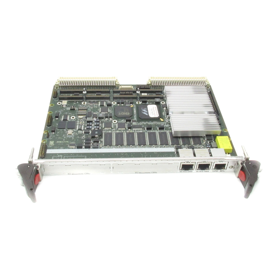
MVME6100 series board with 2eSST performance sustaining 300 MB/s data
transfers
Power cord
Ethernet and serial cables
ESD Precautions
Motorola strongly recommends that you use an antistatic wrist strap and a
Use ESD
conductive foam pad when installing or upgrading a system. Electronic
components, such as disk drives, computer boards, and memory modules, can
be extremely sensitive to electrostatic discharge (ESD). After removing the
component from its protective wrapper or from the system, place the
Wrist Strap
component flat on a grounded, static-free surface (and, in the case of a board,
component side up). Do not slide the component over any surface.
If an ESD station is not available, you can avoid damage resulting from ESD
by wearing an antistatic wrist strap (available at electronic stores) that is
attached to an active electrical ground. Note that a system chassis may not be
grounded if it is unplugged.
Important Information
V6100A/LT1
July 2004
Advertisement

Related Manuals for Motorola MVME6100


Summary of Contents for Motorola MVME6100
- Page 1 Dear Customer: This document provides information to help you start evaluation and development using the MVME6100 single-board computer. It documents the hardware components of your Starter Kit, how to assemble the components, and where to obtain Linux or VxWorks development...
- Page 2 Remove any filler panel that might fill that slot. Install the top and bottom edge of the MVME6100 into the guides of the chassis. Only use injector handles for board insertion to avoid damage/deformation to the front panel and/or PCB. Deformation of the front panel can cause an electrical short or other board malfunction.
- Page 3 Connecting The Serial Cable When the MVME6100 is installed in the chassis, you are ready to connect the serial cable, if required. Use the DB9-to-RJ45 adapter supplied in your kit. The following table shows the pinouts for the DB9 female-to-RJ45 adapter assembly.
- Page 4 For Linux: http://www.motorola.com/linux and click on the Downloads & Support link. For VxWorks Board Support Package (BSP): consult the Wind River web site at: http://www.windriver.com and type MVME6100 into the Search window to easily access the mv6100 BSP.