Table of Contents
Advertisement
Quick Links
TABLE OF CONTENTS
1 Specifications ----------------------------------------------------- 2
2 Pictorial Diagram ------------------------------------------------- 2
3 Schematic Diagram ---------------------------------------------- 2
4 Disassembly and Assembly Instruction ------------------ 3
4.1. Disassembly of Lower Body ---------------------------- 3
4.2. Disassembly of Body Cover ---------------------------- 3
4.3. Disassembly of Main Switch Ass'y -------------------- 4
4.4. Disassembly of Motor ------------------------------------ 5
5 Trouble Shooting Chart ---------------------------------------- 6
6 Exploded View and Replacement Parts List ------------ 7
6.1. Exploded View --------------------------------------------- 7
6.2. Attachment Exploded View ----------------------------- 8
6.3. Packing Instruction ---------------------------------------- 9
Model No.
Destination: Lebanon, Iran (PGF), UAE, Jordan, Egypt,
PAGE
6.4. Replacement Parts List--------------------------------- 10
© 2012 Panasonic Manufacturing Malaysia Berhad
(6100-K). Unauthorized copying and distribution is a
violation of law.
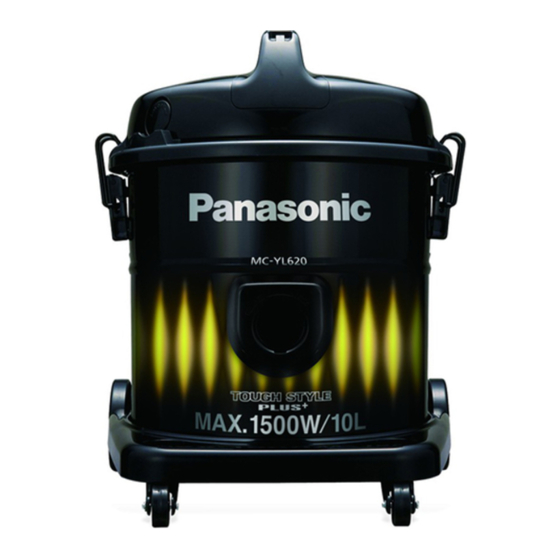
Vacuum Cleaner
MC-YL620Y149-OM
MC-YL620Y149-QA
MC-YL620Y149-LB
MC-YL620Y149-JO
MC-YL620Y149-AE
MC-YL620Y149-EG
MC-YL620Y147-AE
MC-YL620Y147-KW
MC-YL620Y747-SA
Oman, Qatar, Kuwait, Saudi Arabia.
PMMA120922CE
PAGE
Advertisement
Table of Contents

Related Manuals for Panasonic MC-YL620Y149-OM


Summary of Contents for Panasonic MC-YL620Y149-OM
-
Page 1: Table Of Contents
6 Exploded View and Replacement Parts List ------------ 7 6.1. Exploded View --------------------------------------------- 7 6.2. Attachment Exploded View ----------------------------- 8 6.3. Packing Instruction ---------------------------------------- 9 © 2012 Panasonic Manufacturing Malaysia Berhad (6100-K). Unauthorized copying and distribution is a violation of law. -
Page 2: Specifications
1 Specifications Model MC-YL620Y149-OM, MC-YL620Y149-QA, MC-YL620Y14-AE MC-YL620Y149-LB, MC-YL620Y149-JO, MC-YL620Y149-AE, MC-YL620Y149-EG, MC-YL620Y747-SA, MC-YL620Y747-KW Power Source 220V - 240V Frequency (Hz) 50/60Hz, 50Hz Motor Power 1500W 2300W Dimension (L x W x H) 366mm X 340mm X 441mm Nett Weight (kg) 6.0kg... -
Page 3: Disassembly And Assembly Instruction
4 Disassembly and Assem- 4.2. Disassembly of Body Cover Step 1 Remove 4 screws from Upper Body. bly Instruction 4.1. Disassembly of Lower Body Step 1 Release Buckles. Step 2 Take out Body Cover from Upper Body. Step 2 Take out Body Cover from Lower Body. -
Page 4: Disassembly Of Main Switch Ass'y
4.3. Disassembly of Main Switch Step 3 Remove Main Switch Assy from Body Cover. Ass’y Step 1 Remove 2 screws from Body Cover. Step 2 Take out Handle from Body Cover. -
Page 5: Disassembly Of Motor
4.4. Disassembly of Motor Step 1 Take out Noise Absorber. Step 2 Release Wire Connectors from Motor. -
Page 6: Trouble Shooting Chart
5 Trouble Shooting Chart... -
Page 7: Exploded View And Replacement Parts List
6 Exploded View and Replacement Parts List 6.1. Exploded View... -
Page 8: Attachment Exploded View
6.2. Attachment Exploded View... -
Page 9: Packing Instruction
6.3. Packing Instruction... -
Page 10: Replacement Parts List
6.4. Replacement Parts List Safety Ref. No. Part No. Part Name & Description Remarks YMV01B810K0 HANDLE YMC96LDD1V0 BLOWER OULET UNIT YMV98E8110C MAIN SWITCH ASSY YMV24A810K0 BODY COVER UNIT YMC51EBY000 CORD BUSHING YMV30L7X000 OUTLET FILTER XTT4+20BFJ TRUSS TAP SCREW YMV97W8100C FUSE ASSY ( 12A ) YMV46F61000 CAPACITOR (0.22) YMV0NA81000...