
Related Manuals for Keysight M9484C


Summary of Contents for Keysight M9484C
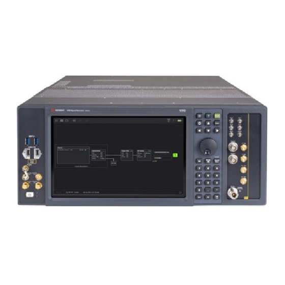
- Page 1 VXG Signal Generator M9484C VXG Vector Signal Generator This manual provides documentation for the M9484C running the Microsoft Windows 10 operating system. GETTING STARTED AND TROUBLESHOOTING GUIDE...
- Page 2 Notices DOCUMENT OR ANY INFORMATION commercial computer software or CONTAINED HEREIN. SHOULD commercial computer software KEYSIGHT AND THE USER HAVE A documentation. No additional © Keysight Technologies, Inc. SEPARATE WRITTEN AGREEMENT government requirements beyond 2021- 2022 WITH WARRANTY TERMS those set forth in the EULA shall...
- Page 3 Information on preventing instrument damage can be found at: http://keysight.com/find/PreventingInstrumentRepair Is your product software up-to-date? Periodically, Keysight releases software updates to fix known defects and incorporate product enhancements. To search for software updates for your product, go to the Keysight Technical Support website at: http://www.keysight.com/find/techsupport...
-
Page 5: Table Of Contents
Verify M9484C Shipment Contents ........ - Page 6 Windows Taskbar Auto-hide Feature ........117 M9484C Startup Guide...
- Page 7 Locations for Keysight Technologies ........
- Page 8 M9484C Startup Guide...
- Page 9 M9484C VXG MIlimeter Wave Vector Signal Generator Startup Guide Quick Start Use this guide to unpack and set up the M9484C VXG Millimeter Wave Signal Generator. The following topics can be found in this section: “Protecting against electrostatic discharge” on page 10 “Unpack and Inspect the Instrument”...
-
Page 10: Quick Start
Additional Information About ESD For more information about ESD and how to prevent ESD damage, contact the Electrostatic Discharge Association (http://www.esda.org). The ESD standards developed by this agency are sanctioned by the American National Standards Institute (ANSI). M9484C Startup Guide... -
Page 11: Unpack And Inspect The Instrument
Remove the instrument from the packaging container and ensure that all accessories are included. Inspect the instrument and accessories for damage. If the contents appear damaged, notify your local Keysight Technologies Inc. representative. The instrument is shipped in a container which prevents damage from static. -
Page 12: Verify M9484C Shipment Contents
83059B Adapter, 3.5 mm (m) to (f) 83059C a. For Option 520 only, each channel of the M9484C VXG includes one 83059B adapter and one 83059C adapter to help interface with the 3.5 mm (m) RF output. Instrument Weight 36.7 kg (approximately) - Page 13 (non-condescending): 95% RH up to º C, decreases linearity to 45% RH at º º º From 40 C to 50 C, the maximum % Relative Humidity follows the line of constant dew point. Altitude (m) 3000 m M9484C Startup Guide...
- Page 14 For example, avoid the situation where the exhaust air from another instrument feeds into the air intake for this instrument. The M9484C VXG has multiple air intakes. They are located at the lower sides, lower front and bottom of the instrument.
-
Page 15: Prepare The Hardware
— Use only the power cord supplied with the chassis. Keysight power cords ensure continuity between the chassis grounding-type power plug and the safety ground terminal at the power outlet. - Page 16 The instrument can operate with mains supply voltage fluctuations up to ± 10% of the nominal voltage. 1. Using the screwdriver, remove the screw as shown below. 2. Attach the ground wire with the ring terminal into the screw thread and tighten back to an original ground point. M9484C Startup Guide...
-
Page 17: Prepare And Power Up The Instrument
1. Make sure that the line cord is plugged into a grounded outlet to establish earth ground. 2. Press the power button to power up the instrument. 3. Allow the VXG to warm up for at least 30 minutes before using. M9484C Startup Guide... -
Page 18: Verify Operation Of The Signal Generator
Quick Start Verify Operation of the Signal Generator Verify Operation of the Signal Generator To verify the operation of the M9484C VXG, run a Self Test and Internal Alignments. Run a Self Test Refer to the “Front and Rear Panel Features” on page 25 for a description of the front and rear panel connectors. -
Page 19: Run Alignments
Run Alignments 1. From the M9484C application, select the Triple-bar icon (top left corner) and then select Settings. 2. Select the Alignment tab > Perform Alignment. The internal alignments calibration will ensure optimal operation of the VXG. - Page 20 Quick Start Verify Operation of the Signal Generator M9484C Startup Guide...
-
Page 21: Generate And View An Output Signal
Quick Start Generate and View an Output Signal Generate and View an Output Signal After verifying the operation of the M9484C VXG, you are ready to make a measurement. The following measurement uses a M9484C VXG to generate the 2 GHz signal and Keysight Signal Analyzer to analyze it. - Page 22 Quick Start Generate and View an Output Signal Repeat the above steps for a M9484C VXG with dual channel configuration, for Channel 2. If your shipment includes a Y1265A spare Solid State Drive, continue with “Putting the Additional SSD Into Service” on page 123 Open the link and click on Technical Support to access the Measurement guide on making basic and 5G NR measurements.
-
Page 23: Shutting Down The Instrument
Power down the instrument using the front panel power button. Press briefly to shut down, press and hold to force a shutdown. Do not power down by removing the power cord. For software controlled shutdown, refer to the SYSTem:PDOWn SCPI commands. M9484C Startup Guide... -
Page 24: Related Documentation
Quick Start Related Documentation Related Documentation The table below provides the list of documentation available for the M9484C VXG. Documentation is updated periodically. For the latest documentation, go to the following URL and select Technical Support: https://www.keysight.com/us/en/product/M9484C/m9484c.html Document Description Format... -
Page 25: Front And Rear Panel Features
M9484C VXG Millimeter Wave Signal Generator Startup Guide 2 Front and Rear Panel Features This section describes the following features: “Front Panel Features” on page 26 — “One Channel, 6 GHz or 8.5 GHz” on page 26 “One Channel, 6.0 GHz or 8.5 GHz, with Analog I/O” on page 29 —... -
Page 26: Front Panel Features
Front and Rear Panel Features Front Panel Features Front Panel Features One Channel Instruments One Channel, 6 GHz or 8.5 GHz For M9484C Option 001and Option 506 or 508 only Item Connector Type Description Name SS - USB 3.0 USB Type-A... - Page 27 50 Ω impedance (nominal) Damage level is outside of -0.5 V to 3.8 V RF Out Type N female RF Output signal, level selected by user interface. 50 Ω impedance (nominal) +30 dBm Max reverse power, 0 VDC maximum M9484C Startup Guide...
- Page 28 M9484C VXG signal generators. Keysight Technologies recommends that you do not connect an external 2.4 GHz or 19.2 GHz signal to the M9484C VXG 2.4 GHz or 19.2 GHz inputs as the instrument specifications will not be covered by the warranty.
- Page 29 Front and Rear Panel Features Front Panel Features One Channel, 6.0 GHz or 8.5 GHz, with Analog I/O For M9484C Option 001, Option 506 or 508, and Option ANI Item Connector Type Description Name SS - USB 3.0 USB Type-A...
- Page 30 Ext 1 or 2 External Inputs 1 and 2 — 16 bit ADC — Selectable input impedance: 50 Ω, 600 Ω, or 1 M Ω — Input Bandwidth: 10 MHz — Input Range: ±1 V (±5 V tolerant) M9484C Startup Guide...
- Page 31 50 Ω impedance (nominal) Damage Level is ±2 V Q+ Out Analog quadrature-phase component of I/Q modulation from channel 1's internal baseband generator. Frequency range is DC to 1000 MHz (nominal) 50 Ω impedance (nominal) Damage Level is ±2 V M9484C Startup Guide...
- Page 32 M9484C VXG signal generators. Keysight Technologies recommends that you do not connect an external 2.4 GHz or 19.2 GHz signal to the M9484C VXG 2.4 GHz or 19.2 GHz inputs as the instrument specifications will not be covered by the warranty.
- Page 33 Front and Rear Panel Features Front Panel Features One Channel, 14 GHz or 20 GHz For M9484C Option 001and Option 514 or 520 Item Connector Type Description Name SS - USB 3.0 USB Type-A Host controller, SuperSpeed, 900 mA (nominal)
- Page 34 Baseband Marker Output #2 Maximum Edge Rate: every 1.667 ns VOL < 0.4 V, VOH is 2.8 V to 3.3 V into high impedance 50 Ω impedance (nominal) Damage level is outside of -0.5 V to 3.8 V M9484C Startup Guide...
- Page 35 M9484C VXG signal generators. Keysight Technologies recommends that you do not connect an external 2.4 GHz or 19.2 GHz signal to the M9484C VXG 2.4 GHz or 19.2 GHz inputs as the instrument specifications will not be covered by the warranty.
- Page 36 Front and Rear Panel Features Front Panel Features One Channel, 14 GHz or 20 GHz, with Analog I/O For M9484C Option 001, Option 514 or 520, and Option ANI Item Connector Type Description Name SS - USB 3.0 USB Type-A...
- Page 37 — 50 Ω output resistance As a receiver: — 5 V input — 5 V tolerant input (damage at 5.5 V) — Selectable input termination (50 Ω or 10 K Ω) — Receiver threshold resolution (5 mV) M9484C Startup Guide...
- Page 38 50 Ω impedance (nominal) Damage Level is ±2 V I- Out Analog in-phase component of I/Q modulation from channel 1's internal baseband generator. Frequency range is DC to 1000 MHz (nominal) 50 Ω impedance (nominal) Damage Level is ±2 V M9484C Startup Guide...
- Page 39 M9484C VXG signal generators. Keysight Technologies recommends that you do not connect an external 2.4 GHz or 19.2 GHz signal to the M9484C VXG 2.4 GHz or 19.2 GHz inputs as the instrument specifications will not be covered by the warranty.
- Page 40 Front and Rear Panel Features Front Panel Features One Channel, 31.8 GHz, 44 GHz, or 54 GHz For M9484C Option 001 and Option 532 or 540 or 554 Item Connector Type Description Name SS - USB 3.0 USB Type-A Host controller, SuperSpeed, 900 mA (nominal)
- Page 41 Dual function connector: ODI receive flow control or trigger input/output 3 Input: 1.8 V LVCMOS 1 MΩ impedance Output: 1.8 V LVCMOS 50 Ω impedance (nominal) Damage level is outside of -0.5 V to 5.5 V LO1 and LO2 APC 3.5 mm 9.6 GHz signal M9484C Startup Guide...
- Page 42 M9484C VXG signal generators. Keysight Technologies recommends that you do not connect an external 2.4 GHz or 19.2 GHz signal to the M9484C VXG 2.4 GHz or 19.2 GHz inputs as the instrument specifications will not be covered by the warranty.
- Page 43 Front and Rear Panel Features Front Panel Features One Channel, 31.8 GHz, 44 GHz, or 54 GHz, with Analog I/O For M9484C Option 001, Option 532 or 540 or 554, and Option ANI Item Connector Type Description Name SS - USB 3.0...
- Page 44 — 50 Ω output resistance As a receiver: — 5 V input — 5 V tolerant input (damage at 5.5 V) — Selectable input termination (50 Ω or 10 K Ω) — Receiver threshold resolution (5 mV) M9484C Startup Guide...
- Page 45 Damage level is outside of -0.5 V to 3.8 V I+ Out Analog In-phase component of I/Q modulation from channel 1's internal baseband generator. Frequency range is DC to 1000 MHz (nominal) 50 Ω impedance (nominal) Damage Level is ±2 V M9484C Startup Guide...
- Page 46 M9484C VXG signal generators. Keysight Technologies recommends that you do not connect an external 2.4 GHz or 19.2 GHz signal to the M9484C VXG 2.4 GHz or 19.2 GHz inputs as the instrument specifications will not be covered by the warranty.
-
Page 47: Two Channel Instruments
Front and Rear Panel Features Front Panel Features Two Channel Instruments Two Channel, 6 GHz or 8.5 GHz For M9484C Option 001 + 002 and 506 or 508 Item Connector Type Description Name SS - USB 3.0 USB Type-A Host controller, SuperSpeed, 900 mA (nominal) - Page 48 50 Ω impedance (nominal) Damage level is outside of -0.5 V to 3.8 V RF Out Type N female RF Output signal, level selected by user interface. 50 Ω impedance (nominal) +30 dBm max reverse power, 0 VDC maximum M9484C Startup Guide...
- Page 49 M9484C VXG signal generators. Keysight Technologies recommends that you do not connect an external 2.4 GHz or 19.2 GHz signal to the M9484C VXG 2.4 GHz or 19.2 GHz inputs as the instrument specifications will not be covered by the warranty.
- Page 50 Front and Rear Panel Features Front Panel Features Two Channel, 6.0 GHz or 8.5 GHz with Analog I/O For M9484C Option 001 + 002, Option 506 or 508, and Option ANI Item Connector Type Description Name SS - USB 3.0...
- Page 51 (5 MHz to 10 MHz) — Output range into 1 M Ω: ±6.5 V (DC to 5 MHz), ±4.5 V (5 MHz to 10 MHz) — Bandwidth: 10 MHz (sine wave); 2 MHz (square and triangle waves) M9484C Startup Guide...
- Page 52 Frequency range is DC to 1000 MHz (nominal) 50 Ω impedance (nominal) Damage Level is ±2 V CH 1 and CH 2 RF Out Type N Female RF Output signal, level selected by user interface. 50 Ω impedance (nominal) +30 dBm, 0 VDC maximum M9484C Startup Guide...
- Page 53 M9484C VXG signal generators. Keysight Technologies recommends that you do not connect an external 2.4 GHz or 19.2 GHz signal to the M9484C VXG 2.4 GHz or 19.2 GHz inputs as the instrument specifications will not be covered by the warranty.
- Page 54 Front and Rear Panel Features Front Panel Features Two Channel, 14 GHz or 20 GHz For M9484C Option 001 + 002 and 514 or 520 Item Connector Type Description Name SS - USB 3.0 USB Type-A Host controller, SuperSpeed, 900 mA (nominal)
- Page 55 Baseband Marker Output #2 Maximum Edge Rate: every 1.667 ns VOL < 0.4 V, VOH is 2.8 V to 3.3 V into high impedance 50 Ω impedance (nominal) Damage level is outside of -0.5 V to 3.8 V M9484C Startup Guide...
- Page 56 M9484C VXG signal generators. Keysight Technologies recommends that you do not connect an external 2.4 GHz or 19.2 GHz signal to the M9484C VXG 2.4 GHz or 19.2 GHz inputs as the instrument specifications will not be covered by the warranty.
- Page 57 Front and Rear Panel Features Front Panel Features Two Channel, 14 GHz or 20 GHz, with Analog I/O For M9484C Option 001 + 002, 514 or 520, and ANI Item Connector Type Description Name SS - USB 3.0 USB Type-A...
- Page 58 — 50 Ω output resistance As a receiver: — 5 V input — 5 V tolerant input (damage at 5.5 V) — Selectable input termination (50 Ω or 10 K Ω) — Receiver threshold resolution (5 mV) M9484C Startup Guide...
- Page 59 50 Ω impedance (nominal) Damage Level is ±2 V Analog in-phase component of I/Q modulation from channel 1's internal baseband generator. Frequency range is DC to 1000 MHz (nominal) 50 Ω impedance (nominal) Damage Level is ±2 V M9484C Startup Guide...
- Page 60 Rx FC/Trig 3 Dual function connector: ODI transmit flow control or trigger input/output 2 Input: 1.8 V LVCMOS 1 MΩ impedance Output: 1.8 V LVCMOS 50 Ω impedance (nominal) Damage level is outside of -0.5 V to 5.5 V M9484C Startup Guide...
- Page 61 M9484C VXG signal generators. Keysight Technologies recommends that you do not connect an external 2.4 GHz or 19.2 GHz signal to the M9484C VXG 2.4 GHz or 19.2 GHz inputs as the instrument specifications will not be covered by the warranty.
- Page 62 Front and Rear Panel Features Front Panel Features Two Channel, 31.8 GHz, 44 GHz, or 54 GHz For M9484C Option 001 + 002, Option 532 or 544 or 554 Item Connector Type Description Name System Sync Up Reserved for future use...
- Page 63 Input: 1.8 V LVCMOS 1 M Ω impedance Output: 1.8 V LVCMOS 50 Ω impedance (nominal) Damage level is outside of -0.5 V to 5.5 V LO 1 and LO 2 APC 3.5 mm 9.6 GHz signal M9484C Startup Guide...
- Page 64 M9484C VXG signal generators. Keysight Technologies recommends that you do not connect an external 2.4 GHz or 19.2 GHz signal to the M9484C VXG 2.4 GHz or 19.2 GHz inputs as the instrument specifications will not be covered by the warranty.
- Page 65 Front and Rear Panel Features Front Panel Features Two Channel, 31.8 GHz, 44 GHz, or 54 GHz with Analog I/O For M9484C Option 001 + 002, Option 532 or 544 or 554, and Option ANI Item Connector Type Description Name...
- Page 66 Output of 19.2 GHz frequency reference. This 19.2 GHz Out connector has a factory installed 50 Ω termination. This port is always on level is 7.3 dBm (nominal), if unused, this port should be terminated with 50 Ω load. On/Off Switch Push Button Power Switch M9484C Startup Guide...
- Page 67 Baseband Marker Output #2 Maximum Edge Rate: every 1.667 ns VOL < 0.4 V, VOH is 2.8 V to 3.3 V into high impedance 50 Ω impedance (nominal) Damage level is outside of -0.5 V to 3.8 V M9484C Startup Guide...
- Page 68 1.85 mm RF Output signal, level selected by user interface. 50 Ω impedance (nominal) +24 dBm maximum reverse power, 0 VDC Optical Digital Interface. Optical interconnect for very high speed streaming applications between instruments, processors, and storage. M9484C Startup Guide...
- Page 69 M9484C VXG signal generators. Keysight Technologies recommends that you do not connect an external 2.4 GHz or 19.2 GHz signal to the M9484C VXG 2.4 GHz or 19.2 GHz inputs as the instrument specifications will not be covered by the warranty.
-
Page 70: Four Channel Instruments
Front and Rear Panel Features Front Panel Features Four Channel Instruments Four Channel, 6 GHz or 8.5 GHz For M9484C Option 001 + 002 + 003 + 004 and Option 506 or 508 Item Connector Type Description Name System Sync Up... - Page 71 Baseband Marker Output #2 Maximum Edge Rate: every 1.667 ns VOL < 0.4 V, VOH is 2.8 V to 3.3 V into high impedance 50 Ω impedance (nominal) Damage level is outside of -0.5 V to 3.8 V M9484C Startup Guide...
- Page 72 M9484C VXG signal generators. Keysight Technologies recommends that you do not connect an external 2.4 GHz or 19.2 GHz signal to the M9484C VXG 2.4 GHz or 19.2 GHz inputs as the instrument specifications will not be covered by the warranty.
- Page 73 Front and Rear Panel Features Front Panel Features Four Channel, 14 GHz or 20 GHz For M9484C Option 001 + 002 + 003 + 004 and Option 514 or 520 Item Connector Type Description Name System Sync Up Reserved for future use...
- Page 74 Baseband Marker Output #1 Maximum Edge Rate: every 1.667 ns VOL < 0.4 V, VOH is 2.8 V to 3.3 V into high impedance 50 Ω impedance (nominal) Damage level is outside of -0.5 V to 3.8 V M9484C Startup Guide...
- Page 75 M9484C VXG signal generators. Keysight Technologies recommends that you do not connect an external 2.4 GHz or 19.2 GHz signal to the M9484C VXG 2.4 GHz or 19.2 GHz inputs as the instrument specifications will not be covered by the warranty.
-
Page 76: Rear-Panel Features
Channel 1 Baseband Waveform Marker Output #1 Maximum Edge Rate: every 1.667 ns VOL < 0.4 V, VOH is 2.8 V to 3.3 V into high impedance 50 Ω impedance (nominal) Damage level is outside of -0.5 V to 3.8 V M9484C Startup Guide... - Page 77 Ports 10 and 11 are connected by a factory installed cable. Synchronization clock input. SClk In 50 Ω impedance. +2 dBm to +12 dBm SClk Out Reserved for future use. Synchronization clock output. 50 Ω impedance. +2 dBm nominal M9484C Startup Guide...
- Page 78 ESD damage level is 30 V a. The SClk In and 100 MHz Out ports are designed for phase coherent operation between one or more M9484C VXG signal generators with Option SNC. The SClk In port should only be used to connect to upstream SClk Out from other VXGs.
-
Page 79: Options 001 + 002 + 003 + 004 (4 Channels)
50 Ω impedance (nominal) ESD damage level is 30 V Ref In Externally supplied 1 MHz to 110 MHz frequency reference, switched by the user interface; off by default. Input level –3 dBm to +20 dBm (nominal), 50 Ω impedance. M9484C Startup Guide... - Page 80 ESD damage level is 30 V a. The SClk In and 100 MHz Out ports are designed for phase coherent operation between one or more M9484C VXG signal generators with Option SNC. The SClk In port should only be used to connect to upstream SClk Out from other VXGs.
-
Page 81: Instrument Operating System
Startup Guide Instrument Operating System This chapter describes the Microsoft Windows configuration and settings used with the Keysight instrument software. It includes information about changing some of the system settings. The following topics can be found in this chapter: “Installed Software ” on page 82 “VXG Licensing Options”... -
Page 82: Installed Software
This chapter contains details about many of these settings. Instrument Software The instrument software is factory installed in the M9484C VXG Millimeter Wave Signal Generator. For optional software and capabilities, you may purchase the license at a later date. -
Page 83: Vxg Licensing Options
Transportable licenses require a connection to the Keysight server only for managing the transfer of the license to and from the instrument. The connection to the Keysight server may be via the instrument itself or an external PC. The Keysight licensing server also provides for storage of unused licenses that have been transported off instruments but are awaiting assignment to new instruments. -
Page 84: Usb Portable Licenses
Configuring Network and USB Licenses The Keysight Floating License Manager must be used to configure the Network or USB Portable licenses before the licenses can be used. An instrument can be configured for Network or USB Portable licenses or both. To set up USB Portable licenses, in the Keysight Floating License Manager select “Start a... - Page 85 To set up both Network and USB Portable license, first configure the USB Portable license, then configure the Network licenses, but append “;@localhost” to the server name (example: “@myserver;@localhost”). Whenever the configuration is changed, the software must be restarted. M9484C Startup Guide...
-
Page 86: User Installation Of Software
Keysight does not warrant the performance of the instruments with non-approved software installed. If you install programs other than those that Keysight has tested, it could cause problems with the instrument's applications. If this happens, you should try uninstalling the program that has caused the problem, or try changing the program's configuration. -
Page 87: User Accounts
User names are not case sensitive but passwords are case sensitive. It is Keysight’s expectation that each user’s Documents folder is mapped to the D: drive. This is to avoid overwriting the user’s data in the event the Instrument Recovery must be performed. -
Page 88: Windows Configuration
If the instrument has Internet access, the instrument default is set to automatically check for critical Windows Updates and notify you. Add the instrument to a network Install and configure a printer Set the time and date M9484C Startup Guide... -
Page 89: Settings That Must Not Be Changed
—Screen resolution (under “Adjust Resolution”) —DPI setting (under “Set custom text size”) CAUTION Do not change any settings under “Region and Language” or the instrument keyboard and display may not operate properly. Do not delete or modify the "KeysightOnly" user account. M9484C Startup Guide... -
Page 90: Autoplay/Autorun
— Add, delete, or modify disk drive partitions. — Delete or modify Keysight registry entries. — Change the contents of any directories containing the name "Keysight". — Stop the IIS server — Tamper with any virtual directories (or their contents) that came configured with the instrument. -
Page 91: Configuring Lan
1. To map a network drive, Select the Start icon , System Tools, Computer. 2. Select the Computer tab, and select Map Network Drive from the dropdown menu. M9484C Startup Guide... - Page 92 Instrument Operating System Configuring LAN 3. Browse to the correct folder, and select Finish. In Windows 10 there is no visual indication that authentication is in progress. M9484C Startup Guide...
-
Page 93: Windows Security
Be aware that downloading and installing Windows Updates can be network and CPU usage intensive (impacting the instrument performance), and some Windows Updates automatically reboot the instrument. It is recommended that Windows Updates be performed when the instrument is not in normal use. M9484C Startup Guide... -
Page 94: Virus Protection
There is no anti-Spyware software installed on the instrument. This should not be a problem if you do not use the instrument for a lot of Internet browsing. Having Spyware in the instrument could have an impact on the instrument performance. M9484C Startup Guide... -
Page 95: Installing And Using An Ftp Server On Windows 10
2. Expand Internet Information Services and select: a. FTP Server and the FTP Extensibility option. b. Expand Web Management Tools and select IIS Management Console, or the default selections. c. Select OK to begin the installation. This will take a couple of minutes. M9484C Startup Guide... -
Page 96: To Configure An Ftp Site
After installation, you need to create an FTP site. 1. In the Program and Features dialog, select Control Panel and search for Administrative Tools, and then open. 2. In the Administrative Tools dialog, double-click on Internet Information Services. M9484C Startup Guide... - Page 97 3. In the right pane, expand and right click on the Sites, and then select Add FTP Site. 4. Name your FTP site and then enter the path to the FTP folder where you want to send and receive files. Select Next to continue. M9484C Startup Guide...
- Page 98 Enter the email address of t Windows 10 account or local account name to allow access to the FTP server. (More than one email address can be added by placing a semicolon in between addresses.) d. Select the Read and Write options. M9484C Startup Guide...
-
Page 99: To Allow An Ftp Server Through Windows Firewall
FTP server. Follow the steps below to allow the FTP server through the firewall. 1. In the Windows Start menu, search on Windows Firewall and open. 2. In the Windows Firewall dialog, select Allow an app or feature through Windows Firewall. M9484C Startup Guide... - Page 100 Now you should be able to use your FTP client to connect to your newly created FTP server, from you local network. If you are using another security software then Windows Firewall, make sure to check your software vendor support website for specific instructions to allow an FTP server. M9484C Startup Guide...
-
Page 101: System Maintenance
However, System Restore is not always 100% successful. Therefore, it is not recommended that you rely on System Restore to protect your instrument. System Restore has not been tested to verify successful restoring. Disk Defragmenting The instrument has a solid state drive. Disk defragmenting is not recommended. M9484C Startup Guide... -
Page 102: Usb Connections
Microsoft Windows USB drivers for human interface, mass storage, printing, scanning, and imaging devices. The USB 3.0 Type C connector is used only for connection to the Keysight V3080A Frequency Extender. (The V3080A is only available on the 32 GHz, 44 GHz, and 54 GHz instruments.) A complete up-to-date list of the Windows USB class driver support is available on the Microsoft website. -
Page 103: Disk Drive Partitioning And Use
— The E: partition is reserved for Keysight’s use. The primary use of the E: drive is for housing the Calibration and Alignment data. Do not change or overwrite the files on this drive. -
Page 104: Disk Drive Recovery Process
Notes 1. Make sure the instrument is turned off. 2. Turn on the instrument. After the Keysight Technologies screen is displayed, — Press the down arrow key to move This screen is displayed for five seconds. the highlight to Instrument... - Page 105 4. A warning message appears. — Press Enter to start the recovery, which may take up to 25 minutes to complete. 5. Press Enter to exit and reboot the instrument once this portion of the recovery has completed. M9484C Startup Guide...
-
Page 106: Updating The Software (Required After A Recovery)
The installation process can take up to 45 minutes. Do not turn the instrument power off or serious damage may occur. If any pop up windows appear, click OK or Ignore to proceed. 4. After the instrument restarts, the newly installed version of the software will run. M9484C Startup Guide... -
Page 107: Using Windows Tools
M9484C VXG Millimeter Wave Signal Generator Startup Guide Using Windows Tools The capabilities described in this section are Microsoft Windows 10 features. The discussion provided here gives some guidelines for using the capabilities with the instrument. You need to refer to the Windows 10 help documentation for more information. -
Page 108: Navigating Windows Without A Mouse
Ctrl + Tab In dialog box: moves to the next/previous Tab location Ctrl + Esc Opens the Windows Start Menu Ctrl + Alt + Opens a window that enables you to select the Windows Task Manager Delete M9484C Startup Guide... -
Page 109: Remote Desktop: Using The Signal Generator Remotely
Figure 4-1 Basic setup for remote desktop operation Enabling Copy and Paste or File Sharing For security purposes the instrument comes from the factory with copy and paste and file sharing disabled in Remote Desktop. To enable edit the registry: M9484C Startup Guide... - Page 110 1. From the Start menu, select Registry Editor. 2. In the left pane of the Registry Editor window, navigate to: HKEY_LOCAL_MACHINE\Software\Policies\Microsoft\Windows NT\Terminal Services 3. Select fDisbaleCdm and set Value data to 1, then select OK. Figure 4-2 Registry Editor setup M9484C Startup Guide...
-
Page 111: Setting Up Remote Desktop Operation On The Instrument
CD-ROM, because that contains the Client software. The following instructions relate to software provided by Microsoft Corporation. Keysight offers no warranty regarding the operation of such software. The procedure described here may be changed by Microsoft at some future time. -
Page 112: How To Locate The Computer Name Of The Instrument
To connect a remote computer to the instrument, you need to know its Computer Name. The Computer Name can be displayed as follows: Table 4-3 Locating the name from the Keysight application Step Notes A page listing various parameters appears.The On the instrument front panel, select >... -
Page 113: Running A Remote Desktop Session
Start menu. If no one is currently logged into the instrument, any valid instrument user can remotely log in. M9484C Startup Guide... - Page 114 2. Under the General tab, ensure You may choose to enter the password and save it for that the Computer name, User future sessions, by selecting the Save my password name and Domain name are set box. correctly. M9484C Startup Guide...
- Page 115 To Optimize the performance of the Remote Desktop session, choose the appropriate connection format from the drop-down list. Ending a Remote Desktop Session There are two ways to disconnect the remote computer from the instrument: ending the session: M9484C Startup Guide...
- Page 116 2.When the remote desktop is full screen, move the cursor to the bottom left of the window: You are asked to confirm that you want to — Select Start > Disconnect. disconnect. — Select Disconnect. M9484C Startup Guide...
-
Page 117: Windows Shortcuts And Miscellaneous Tasks
See also “Navigating Windows Without a Mouse”. Although these shortcuts are available in any Windows 10 system, they are not commonly used when a mouse and keyboard are attached. M9484C Startup Guide... -
Page 118: Windows Shortcuts (Key Combinations)
In a dialog list box or check box: select or clear one Arrow item at a time In My Computer, expand a selected folder Enter In My Computer, open a folder one level up from Bk Sp the current folder M9484C Startup Guide... -
Page 119: Windows Taskbar Auto-Hide Feature
118 make these selections. 3. Select Auto-hide the taskbar in desktop If you are not using a mouse, press Tab mode repeatedly until the auto-hide option is selected, then press Select to toggle the checkbox state. M9484C Startup Guide... - Page 120 Using Windows Tools Windows Shortcuts and Miscellaneous Tasks M9484C Startup Guide...
-
Page 121: Removable Solid State Drive (Ssd)
M9484C VXG Millimeter Wave Signal Generator Startup Guide Removable Solid State Drive (SSD) The following topics can be found in this section: “Overview” on page 122 “Putting the Additional SSD Into Service” on page 123 “SSD Interconnect Life Expectancy” on page 124 “SSD Removal and Installation”... -
Page 122: Overview
Y1277A along with your M9484C VXG, follow the instructions below. The SSD is mounted in a receptacle on the rear panel of the M9484C chassis and can be easily inserted or removed. This is convenient when multiple people are using the same VXG and they do not want to interfere with the other person’s project or for use in a controlled secure environment. -
Page 123: Putting The Additional Ssd Into Service
— The same version of instrument software/firmware that is also installed in the instrument. — The instruments computer name. — Instrument specific configurations. Contact Keysight to install existing M9484C options onto the new SSD drive. Refer to “Calling Keysight Technologies” on page 138. -
Page 124: Ssd Interconnect Life Expectancy
The life expectancy of both the connector on the removable SSD and the mating connector internal to the instrument is 100 cycles. If this is exceeded it is very likely that a failure will occur between these connections. Keysight highly recommends that this cycle limit not be exceeded to prevent an unwanted failure of the instrument. -
Page 125: Ssd Removal And Installation
3. Pull on the handle to unseat the SSD and remove the SSD. 4. Install the new SSD by aligning the SSD PC board edges with the card guides. Insert the SSD completely. 5. Tighten the screw to no more than 9 in-lbs. M9484C Startup Guide... -
Page 126: Firmware Updates
Triple-bar icon > Settings > Firmware Version. If an instrument firmware update is required, the latest revision of the firmware can be found by going to: https://www.keysight.com/us/en/product/M9484C/m9484c.html and selecting the Drivers, Firmware, and Software tab. M9484C Startup Guide... -
Page 127: Instrument Security Information
Removable Solid State Drive (SSD) Instrument Security Information Instrument Security Information Information on the instrument security features and the instrument volatility can be found at: http://www.keysight.com/find/security M9484C Startup Guide... - Page 128 Removable Solid State Drive (SSD) Instrument Security Information M9484C Startup Guide...
-
Page 129: Safety And Maintenance Information
M9484C VXG Millimeter Wave Vector Signal Generator Startup Guide Safety and Maintenance Information The following topics can be found in this section: “Safety Information” on page 130 “Warnings, Cautions, and Notes” on page 131 “Instrument Markings” on page 134 “Instrument Maintenance” on page 137... - Page 130 10°C from the lowest, of the maximum operating temperature of a single instrument. If there are any concerns or special requirements a Keysight Field Engineer should be consulted to assure instrument(s) temperature compliance and performance.
- Page 131 Do not proceed beyond a caution until you fully understand the indicated conditions. Note calls the user’s attention to an important point or special information in the text. M9484C Startup Guide...
-
Page 132: General Safety Considerations
This product must be used in a normal condition (in which all means for protection are intact) only. The M9484C VXG is heavy and requires two people to lift and carry it. Instrument is front heavy.Do not attempt to lift or carry it on your own. -
Page 133: Servicing
No operator serviceable parts inside. Refer servicing to qualified personnel. To prevent electrical shock do not remove covers. Operating Conditions This product is designed for use in Installation Category II and Pollution Degree 2. M9484C Startup Guide... -
Page 134: Instrument Markings
This symbol indicates the surface can be hot. This symbol indicated the product is sensitive to electrostatic discharge. This symbol identifies the Protective Conductor terminal. This symbol indicates the equipment is protected throughout by double or reinforced insulation. M9484C Startup Guide... - Page 135 The UK conformity mark is a UK government owned mark. Products showing this mark comply with all applicable UK regulations. The Keysight email address is required by EU directives applicable to our product. The CSA mark is a registered trademark of the CSA International.
- Page 136 GB 18455-2001 as required by the China RoHS regulations for paper/fiberboard packaging. This mark indicates product has been designed to meet the requirements of "IP x y", where "x" is the solid particle protection and "y" is the liquid ingress protection. M9484C Startup Guide...
-
Page 137: Instrument Maintenance
Instrument Maintenance Instrument Maintenance Cleaning the instrument To remove dirt or dust from the external case of the M9484C VXG, clean the case using a dry or slightly-dampened cloth only. Cleaning Connectors Cleaning connectors with alcohol shall only be done with the instrument power cord removed, and in a well-ventilated area. -
Page 138: Returning An Instrument For Service
Returning an Instrument for Service Returning an Instrument for Service Calling Keysight Technologies Keysight Technologies has offices around the world to provide you with complete support for your instrument. To obtain servicing information or to order replacement parts, contact the nearest Keysight Technologies office listed below. -
Page 139: Service Options
M9484C Rear Panel and Front Panel jumper cables (PN: W1312-20511 and W1312-20516) come with protective caps to protect them from impact damage during shipping. When returning an instrument for service, reinsert the protective caps (if available) or remove the cables and place them in a separate protective bag. - Page 140 4. Seal the shipping container securely with strong nylon adhesive tape. 5. Mark the shipping container “FRAGILE, HANDLE WITH CARE” to assure careful handling. 6. Retain copies of all shipping papers. M9484C Startup Guide...
- Page 141 This information is subject to change without notice. © Keysight Technologies 2022 Edition 1, October 2022 M9484-90001 www.keysight.com...
Need help?
Do you have a question about the M9484C and is the answer not in the manual?
Questions and answers