Table of Contents
Advertisement
Advertisement
Table of Contents

Subscribe to Our Youtube Channel
Related Manuals for Supermicro H13SSL-N


Summary of Contents for Supermicro H13SSL-N
- Page 1 H13SSL-N H13SSL-NT USER’S MANUAL Revision 1.0...
- Page 2 State of California, USA. The State of California, County of Santa Clara shall be the exclusive venue for the resolution of any such disputes. Supermicro's total liability for all claims will not exceed the price paid for the hardware product.
- Page 3 About This Manual This manual is written for system integrators, IT technicians and knowledgeable end users. It provides information for the installation and use of the H13SSL-N/NT motherboard. About This Motherboard Built upon the functionality and capability of the AMD EPYC...
-
Page 4: Contacting Supermicro
H13SSL-N/NT User's Manual Contacting Supermicro Headquarters Address: Super Micro Computer, Inc. 980 Rock Ave. San Jose, CA 95131 U.S.A. Tel: +1 (408) 503-8000 Fax: +1 (408) 503-8008 Email: marketing@supermicro.com (General Information) Sales-USA@supermicro.com (Sales Inquiries) Government_Sales-USA@supermicro.com (Gov. Sales Inquiries) support@supermicro.com (Technical Support) RMA@supermicro.com (RMA Support) -
Page 5: Table Of Contents
Preface Table of Contents Contacting Supermicro ......................4 Chapter 1 Introduction 1.1 Quick Reference .........................10 Quick Reference Table ......................11 Motherboard Features .......................13 Chipset Block Diagram......................15 1.2 Processor and Chipset Overview ..................16 1.3 Special Features ........................16 Recovery from AC Power Loss ..................16 1.4 System Health Monitoring ....................17... - Page 6 H13SSL-N/NT User's Manual 2.7 Connectors .........................38 2.8 Connectors .........................41 2.9 Jumper Settings .........................46 How Jumpers Work ......................46 2.10 LED Indicators ........................48 Chapter 3 Troubleshooting 3.1 Troubleshooting Procedures ....................51 Before Power On ......................51 No Power ..........................51 No Video ...........................52 System Boot Failure ......................52 Memory Errors ........................52...
-
Page 7: Chapter 1 Introduction
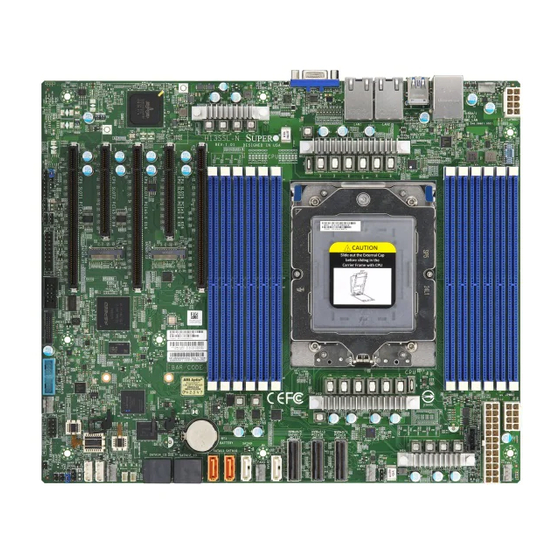
• If you have any questions, please contact our support team at: support@supermicro.com This manual may be periodically updated without notice. Please check the Supermicro website for possible updates to the manual revision level. - Page 8 H13SSL-N/NT User's Manual Figure 1-1. H13SSL-N Motherboard Image Note: All graphics shown in this manual were based upon the latest PCB revision available at the time of publication of the manual. The motherboard you received may or may not look...
- Page 9 Chapter 1: Introduction Figure 1-2. H13SSL-NT Motherboard Image Note: All graphics shown in this manual were based upon the latest PCB revision available at the time of publication of the manual. The motherboard you received may or may not look exactly the same as the graphics shown in this manual.
-
Page 10: Quick Reference
JIPMB1 Battery SATA0-7 SATA12_13 (BT1) SATA8 JSATA1 SATA14_15 Figure 1-3. H13SSL-N/NT Layout Notes: • Chapter 2 for detailed information on jumpers, I/O ports, and JF1 front panel connec- tions. • Jumpers/LED indicators not indicated are used for testing only. •... -
Page 11: Quick Reference Table
Chapter 1: Introduction Quick Reference Table Jumper Description Default Setting UID SW Unit ID switch (push-button toggle switch ON/OFF) Off JBT1 CMOS Clear Open (Normal) JSATA1 Hybrid MCIO select Pins 1-2 (Auto) JPL1 LAN Enable/Disable Pins 1-2 (Enabled) Description Status UID_LED UID LED Solid blue: UID switched to ON, unit identified... - Page 12 H13SSL-N/NT User's Manual Connector Description PWRI2C Power supply SMBus I C header PCIe 1, 3, 5 CPU Slot PCIe 5.0 x16 PCIe 2, 4 CPU Slot PCIe 5.0 x8 Note: Jumpers, connectors, switches, and LED indicators that are not described in the preceding tables are for manufacturing testing purposes only, and are not covered in this manual.
-
Page 13: Motherboard Features
• Two PCIe 5.0 x8 connectors • Two M.2 connectors (PCIe 5.0 x4) Network • H13SSL-N: two RJ45, Broadcom BCM5720L 1GbE LAN ports • H13SSL-NT: two RJ45, Broadcom BCM57416 10GbE LAN ports Graphics • ASPEED AST2600 BMC chip I/O Devices •... - Page 14 H13SSL-N/NT User's Manual Fan Control • One 4-pin fan header (spare) • Fan speed control System Management • IPMIView/SMCIPMITOOL/IPMICFG • SuperDoctor® 5 • SDO/SPM/SSM/SUM-OOB/InBand • Trusted Platform Module (TPM) support LED Indicators • Power / Suspend-state Indicator • UID / Remote UID Dimensions •...
-
Page 15: Chipset Block Diagram
Chapter 1: Introduction Chipset Block Diagram H13SSL-N/NT AMD SP5 Rev. 1.01 IPMI LAN 10Gb LAN 10Gb LAN JUSB1 RJ45 RJ45 RJ45 COM1 RTL8211F USB 3.0 USB 3.0 USB 3.0 DDR4 AST2600 SLOT2 SLOT4 BCM57416 UPD720202 UPD720202 BMC ROM PCIe x8... -
Page 16: Processor And Chipset Overview
• System Management Bus (SMBus) Specification Version 3.1.1 1.3 Special Features This section describes the health monitoring features of the H13SSL-N/NT motherboard. The motherboard has an onboard System Hardware Monitor chip that supports system health monitoring. Recovery from AC Power Loss The Basic I/O System (BIOS) provides a setting that determines how the system will respond when AC power is lost and then restored to the system. -
Page 17: System Health Monitoring
Chapter 1: Introduction 1.4 System Health Monitoring This section describes the health monitoring features of the H13SSL-N/NT motherboard. The motherboard has an onboard Baseboard Management Controller (BMC) chip that supports system health monitoring. Once a voltage becomes unstable, a warning is given or an error message is sent to the screen. -
Page 18: Acpi Features
H13SSL-N/NT User's Manual 1.5 ACPI Features ACPI stands for Advanced Configuration and Power Interface. The ACPI specification defines a flexible and abstract hardware interface that provides a standard way to integrate power management features throughout a computer system including its hardware, operating system and application software. -
Page 19: Chapter 2 Installation
Chapter 2: Installation Chapter 2 Installation 2.1 Static-Sensitive Devices Electrostatic Discharge (ESD) can damage electronic com ponents. To prevent damage to your motherboard, it is important to handle it very carefully. The following measures are generally sufficient to protect your equipment from ESD. Precautions •... -
Page 20: Motherboard Installation
H13SSL-N/NT User's Manual 2.2 Motherboard Installation All motherboards have standard mounting holes to fit different types of chassis. Make sure that the locations of all the mounting holes for both the motherboard and the chassis match. Although a chassis may have both plastic and metal mounting fasteners, metal ones are highly recommended because they ground the motherboard to the chassis. - Page 21 Chapter 2: Installation Figure 2-1. Motherboard Mounting Holes...
-
Page 22: Installing The Motherboard
H13SSL-N/NT User's Manual Installing the Motherboard 1. Install the I/O shield into the back of the chassis. 2. Locate the mounting holes on the motherboard. See the previous page for the location. 3. Locate the matching mounting holes on the chassis. Align the mounting holes on the motherboard against the mounting holes on the chassis. -
Page 23: Processor And Heatsink Installation
CPU socket cap is in place and none of the socket pins are bent; otherwise, contact your retailer immediately. • Refer to the Supermicro website for updates on CPU support. Installing the Processor and Heatsink 1. Unscrew the screw #1 holding down the force frame. - Page 24 H13SSL-N/NT User's Manual 2. The spring-loaded force frame will raise up after the screw securing it (#1) is removed. Gently allow it to lift up to its stopping position. 3. Lift the rail frame up by gripping the lift tabs near the front end of the rail frame. While keeping a secure grip of the rail frame, lift it to a position so you can do the next step of removing the external cap.
- Page 25 Chapter 2: Installation 4. Remove the external cap from the rail frame by pulling it upwards through the rail guides on the rail frame. External Cap PnP Cover Cap 5. The CPU package is shipped from the factory with the carrier frame pre-assembled. Grip the handle of the carrier frame/CPU package assembly from its shipping tray, and while gripping the handle, align the flanges of the carrier frame onto the rails of the rail frame so its pins will be at the bottom when the rail frame is lowered later.
- Page 26 H13SSL-N/NT User's Manual Note: You can only install the CPU inside the socket in one direction with the handle at the top. Make sure that it is properly inserted into the CPU socket before closing the rail frame plate. If it doesn't close properly, do not force it as it may damage your CPU. Instead, open the rail frame plate again, and double-check that the CPU is aligned properly.
- Page 27 Chapter 2: Installation 8. Gently lower the rail frame down onto the socket until the latches on the rail frame engage with the socket housing and it rests in place. DO NOT force it into place! 9. The force frame is spring loaded and has to be held in place before it is secured. Important: Use a torque screwdriver, set it at 12.5~15.0 kgf-cm (10.85~13.01 lbf-in) with a Torx T20 screw head bit, to prevent damage to the CPU.
- Page 28 H13SSL-N/NT User's Manual 10. Replace and tighten the screws in the same order you removed them. When finished, the force frame will be secure over both the rail frame and CPU package. 11. After the force frame is secured and the CPU package is in place, now you must install the heatsink to the frame.
- Page 29 Chapter 2: Installation 12. Using a diagonal pattern, tighten the six screws down on the heatsink in a clockwise fashion. The heatsink will now be secured and you have finished installing the processor and heatsink onto the motherboard. Repeat this procedure for any remaining CPU sockets on the motherboard.
- Page 30 H13SSL-N/NT User's Manual Un-installing the Processor and Heatsink 1. Remove the heatsink attached to the top of the CPU package by reversing the installation procedure. 2. Clean the thermal grease left by the heatsink on the CPU package lid to limit the risk of it contaminating the CPU package land pads or contacts in the socket housing.
-
Page 31: Memory Support And Installation
Memory Support The H13SSL-N/NT supports up to 6TB of ECC DDR5 4800 MT/s speed, RDIMM/LRDIMM/3DS memory in twelve slots. Refer to the table below for additional memory information. Note: Check the Supermicro website for possible updates to memory support. - Page 32 H13SSL-N/NT User's Manual Populating RDIMM/RDIMM 3DS DDR5 Memory Modules with Genoa Processor Capacity DIMM Type DDR5 Frequency MT/s (16 Gb x4 Population devices) 14-layer 93mil high- 14-layer 74mil low-Dk 16-layer 93mil high- 1 channel / DIMM Type DIMM 0 Dk PCB stackup...
-
Page 33: Dimm Module Population Sequence
The motherboard will support odd-numbered modules (1 or 3 modules installed). However, to achieve the best memory performance, fully populate the motherboard with validated memory modules. LEDBMC JUID1 FAN4 JUSB1 JPWR1 LAN1 LAN2 H13SSL-N REV:1.00 DESIGNED IN USA DIMML1 DIMMK1 DIMMJ1 DIMMI1 DIMMH1 DIMMG1 LED7 LED8 M.2-H2... -
Page 34: Dimm Installation
H13SSL-N/NT User's Manual DIMM Installation 1. Insert the desired number of DIMMs into the memory slots, see Section 2.4 details installing memory. 2. Push the release tabs outwards on both ends of the DIMM slot to unlock it. Receptive Point 3. -
Page 35: Rear I/O Ports
2.5 Rear I/O Ports See Figure below for the locations and descriptions of the various I/O ports on the rear of the motherboard. LEDBMC JUID1 FAN4 JUSB1 JPWR1 LAN1 LAN2 H13SSL-N REV:1.00 DESIGNED IN USA LED7 LED8 M.2-H2 M.2-H1 SATA24-27 SATA20-23 IPMI CODE... - Page 36 There are four USB 3.0 ports (USB0/1 and USB2/3) on the I/O back panel. These support the type A connector. 6~7. Gigabit LAN Ports The H13SSL-NT has two Broadcom BCM57416 10GbE LAN ports and the H13SSL-N has two Broadcom BCM5720L 1GbE LAN ports located on the I/O back panel. These ports accept RJ45 type cables.
-
Page 37: Front Control Panel
JF1 contains header pins for various buttons and indicators that are normally located on a control panel at the front of the chassis. These connectors are designed specifically for use LEDBMC JUID1 with Supermicro chassis. See the figure below for the location of JF1. JUSB1 LAN1 LAN2 H13SSL-N REV:1.00... -
Page 38: Connectors
H13SSL-N/NT User's Manual 2.7 Connectors Power Switch The Power Switch connection is located on pins 1 and 2 of JF1. Attach it to a hardware power switch on the computer case to power on/off the system. To force the system to be powered off, press the button for at least four seconds. - Page 39 Note: UID can also be triggered via IPMI on the serverboard. For more information on IPMI, please refer to the IPMI User's Guide posted on our website at http://www.supermicro.com. UID LED Pin Definitions (JF1)
- Page 40 H13SSL-N/NT User's Manual Power LED The Power LED connection is located on pins 15 and 16 of JF1. Attach a cable to pin 15 and pin 16 to show system power status. Refer to the table below for pin definitions.
-
Page 41: Connectors
Chapter 2: Installation 2.8 Connectors Main Power Supply Connector (JPWR3) The primary power supply connector (JPWR3) is an ATX power connector that the power supply plugs directly into. ATX Power 24-pin Connector Pin Definitions Pin# Definition Pin# Definition +3.3V +3.3V -12V +3.3V Ground... - Page 42 H13SSL-N/NT User's Manual NVMe Ports (NVMe 0~1, 2~3) The H13SSL-N/NT has four NVMe ports (two ports per one MCIO connector). These ports provide high-speed, low-latency PCIe 5.0 x4 connections directly from the CPU to NVMe Solid State (SSD) drives. This greatly increases SSD data-throughput performance and significantly reduces PCIe latency by simplifying driver/software requirements resulting from direct PCIe interface from the CPU to the NVMe SSD drives.
- Page 43 Chapter 2: Installation USB Ports (USB0~USB5) There are a total of six USB ports supported on the motherboard. Four are located on the back panel. There are also two ports located on one header, USB4/5 (3.0). Front Panel USB 3.0 Pin Definitions Pin# Definition...
- Page 44 H13SSL-N/NT User's Manual Chassis Intrusion (JL1) A Chassis Intrusion header is located at JL1 on the motherboard. Attach the appropriate cable from the chassis to the header to inform you when the chassis has been opened. Chassis Intrusion Pin Definitions...
- Page 45 Chapter 2: Installation SATA (SATA8~15) The H13SSL-N/NT has eight available SATA 3.0 ports (SATA10 and SATA11). SATA Connectors Pin Definitions Pin# Signal Ground SATA_TXP SATA_TXN Ground SATA_RXN SATA_RXP Ground Power SMB Header (PWRI Power System Management Bus (I C) header monitors power supply, fan and system temperatures.
-
Page 46: Jumper Settings
H13SSL-N/NT User's Manual 2.9 Jumper Settings How Jumpers Work To modify the operation of the motherboard, jumpers can be used to choose between optional settings. Jumpers create shorts between two pins to change the function of the connector. Pin #1 is identified with a thicker border line on the printed circuit board. See the diagram below for an example of jumping pins 1 and 2. - Page 47 Chapter 2: Installation JSATA1 The 3-pin jumper at JSATA1 provides the option to switch the hybrid port (JMCIO3) between SATA/NVMe. Refer to the table below for pin definitions. JSATA1 Pin Definitions Pin# Definition Auto (Depends on system configuration) SATA Open NVMe Watch Dog (JWD1) JWD1 controls the Watch Dog function.
-
Page 48: Led Indicators
H13SSL-N/NT User's Manual 2.10 LED Indicators LAN Port LEDs The motherboard's Ethernet ports have two LED indicators. The Activity LED is green and indicates connection and activity. The Link LED may be green, orange, or off to indicate the speed of the connection. Refer to the tables below for more information. - Page 49 Chapter 2: Installation UID LED Indicator (LED1) The rear LED1 is located next to the UID switch. The front UID LED is located on the front panel. When you press the UID switch, both rear LED1 and front UID LED indicators will turn on.
- Page 50 H13SSL-N/NT User's Manual Onboard Power OK LED (LED6) LED6 is an onboard power OK LED. When this LED6 is lit, it means the system is turned on, and all the system power rails are ready. When the system is turned off, or any one of the system power rails fail, this LED will turn off.
-
Page 51: Chapter 3 Troubleshooting
Chapter 3: Troubleshooting Chapter 3 Troubleshooting 3.1 Troubleshooting Procedures Use the following procedures to troubleshoot your system. If you have followed all of the procedures below and still need assistance, refer to the ‘Technical Support Procedures’ and/ or ‘Returning Merchandise for Service’ section(s) in this chapter. Always disconnect the AC power cord before adding, changing or installing any non hot-swap hardware components. -
Page 52: No Video
H13SSL-N/NT User's Manual No Video 1. Check that the VGA cable is connected properly, and the monitor is on. 2. Check if you follow the guidelines to install the memory module (see DIMM Module Population in chapter 2). 3. Reseat the memory DIMM module. -
Page 53: When The System Becomes Unstable
2. Memory support: Make sure that the memory modules are supported by testing the modules using memtest86 or a similar utility. Note: Refer to the product page on our website at http://www.supermicro.com for memory and CPU support and updates. 3. HDD support: Make sure that all hard disk drives (HDDs) work properly. Replace the bad HDDs with good ones. -
Page 54: Technical Support Procedures
3.3 Frequently Asked Questions Question: What type of memory does my motherboard support? Answer: The H13SSL-N/NT motherboard supports up to 6TB of ECC DDR5 4800 MT/s speed, RDIMM/LRDIMM/3DS/NVDIMM memory in twelve slots. See Section 2.4 for details on installing memory. - Page 55 Updated BIOS files are located on our website at http://www. supermicro.com. Please check our BIOS warning message and the information on how to update your BIOS on our website. Select your motherboard model and download the BIOS file to your computer.
-
Page 56: Returning Merchandise For Service
H13SSL-N/NT User's Manual 3.4 Returning Merchandise for Service A receipt or copy of your invoice marked with the date of purchase is required before any warranty service will be rendered. You can obtain service by calling your vendor for a Returned Merchandise Authorization (RMA) number. -
Page 57: Proper Battery Disposal
Chapter 3: Troubleshooting Proper Battery Disposal Please handle used batteries carefully. Do not damage the battery in any way; a damaged battery may release hazardous materials into the environment. Do not discard a used battery in the garbage or a public landfill. Please comply with the regulations set up by your local hazardous waste management agency to dispose of your used battery properly. -
Page 58: Chapter 4 Uefi Bios
UEFI BIOS 4.1 Introduction This chapter describes the AMIBIOS™ Setup utility for the H13SSL-N/NT motherboard. The BIOS is stored on a chip and can be easily upgraded using a flash program. Note: Due to periodic changes to the BIOS, some settings may have been added or deleted and might not yet be recorded in this manual. -
Page 59: Main Setup
Chapter 4: UEFI BIOS 4.2 Main Setup When you first enter the AMI BIOS setup utility, you will enter the Main setup screen. You can always return to the Main setup screen by selecting the Main tab on the top of the screen. The Main BIOS setup screen is shown below. - Page 60 H13SSL-N/NT User's Manual Supermicro H13SSL-N/NT BIOS Version This feature displays the version of the BIOS ROM used in the system. Build Date This item displays the date when the version of the BIOS ROM used in the system was built.
-
Page 61: Advanced
Chapter 4: UEFI BIOS 4.3 Advanced Use the arrow keys to select a top item and press <Enter> to access the submenu items: Warning: Take caution when changing the Advanced settings. An incorrect value, a very high DRAM frequency, or an incorrect DRAM timing setting may make the system unstable. - Page 62 H13SSL-N/NT User's Manual Bootup NumLock State Use this feature to set the Power on state for the <Numlock> key. The options are On and Off. Wait For "F1" If Error Use this feature to force the system to wait until the 'F1' key is pressed if an error occurs.
- Page 63 Chapter 4: UEFI BIOS CPU Configuration CPU Configuration SMT Control Use this setting to specify Simultaneous Multithreading. Options include Disabled and Auto. Core Performance Boost This setting is used to configure for Core Performance Boost. Options include Disabled and Auto.
- Page 64 H13SSL-N/NT User's Manual L1 Stream HW Prefetcher / L2 Stream HW Prefetcher This setting is used to enable or disable the L1/L2 Stream Hardware Prefetcher. The options are Disabled, Enabled and Auto. CCD Control Use this setting to disable CCDs in the CPU. Options include Auto, 2 CCDs, 4 CCDs, 6CCDs, 8 CCDs and 10 CCDs.
- Page 65 Chapter 4: UEFI BIOS CPU1 PCIe Package Group P3 This setting selects the PCIe port bifurcation configuration for the selescted slot. The options include Auto, x4x4x4x4, x4x4x8, x8x4x4, x8x8 and x16. CPU1 PCIe Package Group G3 This setting selects the PCIe port bifurcation configuration for the selescted slot. The options include Auto, x4x4x4x4, x4x4x8, x8x4x4, x8x8, x16 and SATA (M.2).
- Page 66 H13SSL-N/NT User's Manual APBDIS Use this setting to set APBDIS. Options include 0, 1 and Auto. Power Profile Selection Options include High Performance Mode, Efficiency Mode and Maximum IO Performance Mode. DF Cstats Use this setting to enable/disable DF Cstates. Options include Disabled, Enabled and Auto.
- Page 67 Chapter 4: UEFI BIOS CPU1 Memory Information CPU1 Memory Information These sections are for informational purposes. They will display some details about the detected memory according to each CPU on the motherboard, such as: • Detected Size (per slot, in MB) •...
- Page 68 H13SSL-N/NT User's Manual Super IO Configuration Super IO Configuration The following Super IO information will display: • Super IO Chip AST2600 Serial Port 1 Configuration Serial Port 1 Configuration Serial Port Select Enabled to enable the selected onboard serial port. The options are Disabled and Enabled.
- Page 69 Chapter 4: UEFI BIOS Serial Port Console Redirection COM1 Console Redirection Select Enabled to enable console redirection support for a serial port specified by the user. The options are Disabled and Enabled. Console Redirection Select Enabled to enable console redirection support for a serial port specified by the user. The options are Disabled and Enabled.
- Page 70 H13SSL-N/NT User's Manual Stop Bits A stop bit indicates the end of a serial data packet. Select 1 Stop Bit for standard serial data communication. Select 2 Stop Bits if slower devices are used. The options are 1 and 2.
- Page 71 Chapter 4: UEFI BIOS PCIe/PCI/PnP Configuration This menu provides PCIe/PCI/PnP configuration settings and information. PCI Bus Driver Version PCI Devices Common Settings: Above 4G Decoding This setting Disables or Enables 64-bit capable devices ability to be decoded in above 4G address space (only if the system supports 64-bit PCI decoding).
- Page 72 H13SSL-N/NT User's Manual No Snoop Select Enable to support no-snoop mode for each CB device. The options are Disabled and Enabled. VGA Priority Use this setting to select between onboard or external VGA support. The options are Auto, Onboard and External.
- Page 73 Chapter 4: UEFI BIOS Legacy USB Support Select Enabled to support onboard legacy USB devices. Select Auto to disable legacy support if there are no legacy USB devices present. Select Disable to have all USB devices available for EFI applications only. The options are Enabled, Disabled and Auto. XHCI Hand-Off This is a work-around solution for operating systems that do not support XHCI (Extensible Host Controller Interface) hand-off.
- Page 74 H13SSL-N/NT User's Manual Media Detect Count This setting allows you set in a number field the number of times presence of media will be checked. The default value is 1. MAC: 3CECEFCF5428-IPv4 Network Configuration Configured This setting indicates whether network address configured successfully or not. The options include Disabled and Enabled.
- Page 75 Chapter 4: UEFI BIOS MAC: 3CECEFCF5429-IPv6 Network Configuration Enter Configuration Menu Interface ID This 64 bit alternative interface ID for the device. The string is colon separated. DAD Transmit Count The default value is 1. Policy The options are automatic and manual. Save Changes and Exit This setting saves changes and exit.
- Page 76 Enter IP4 address in dotted-decimal notation. Supermicro KMS TCP Port number Enter Supermicro KMS TCP port number. The default setting is 5696. KMS Time Out KMS Server connecting time-out, unit is second, in the range of 5~30 seconds. The default...
- Page 77 Chapter 4: UEFI BIOS Supermicro KMS Server Retry Count Test connection to key manage server. range is 0~10. 0 means retrying infinitely. Others mean retry-count. The default value is 2. TimeZone Enter the correct timezone. The default value is 0.
- Page 78 H13SSL-N/NT User's Manual MBA Configuration Menu Legacy Boot Protocol Select a non-UEFI Boot protocol. The options are PXE, iSCSI, None. Boot Strap Type This setting controls the boot strap method used to boot to the operating system. The options are Auto Detect, BBS, Int 18h and Int 19h.
- Page 79 Chapter 4: UEFI BIOS iSCSI Parameters via DHCP This setting enables the acquisition of iSCSI target parameters from DHCP. The options include Disabled and Enabled. CHAP Authentication This setting enables the ability of the initiator to use CHAP authertication when connect- ing to the iSCSI target.
- Page 80 H13SSL-N/NT User's Manual iSCSI Second Target Parameters This setting enables connection and configure communication parameters for the second iSCSI target. Secondary Device Thie setting inputs secondary device MAC address. Blink LEDs Blink LEDs for a duration up to 15 seconds. The default value is 0.
- Page 81 Chapter 4: UEFI BIOS MBA Configuration Menu Legacy Boot Protocol Select a non-UEFI Boot protocol. The options are PXE, iSCSI, None. Boot Strap Type This setting controls the boot strap method used to boot to the operating system. The options are Auto Detect, BBS, Int 18h and Int 19h. Hide Setup Prompt Use this setting to configure whether setup prompt is displayed during ROM initialization.
- Page 82 H13SSL-N/NT User's Manual iSCSI Parameters via DHCP This setting enables the acquisition of iSCSI target parameters from DHCP. The options include Disabled and Enabled. CHAP Authentication This setting enables the ability of the initiator to use CHAP authertication when connect- ing to the iSCSI target.
- Page 83 Chapter 4: UEFI BIOS iSCSI Second Target Parameters This setting enables connection and configure communication parameters for the second iSCSI target. Secondary Device Thie setting inputs secondary device MAC address. Blink LEDs Blink LEDs for a duration up to 15 seconds. Link Status Disconnected Permanent MAC Address...
-
Page 84: Bmc
H13SSL-N/NT User's Manual 4.4 BMC This tab allows you to configure the following IPMI settings for the system. Use this feature to configure Intelligent Platform Management Interface (IPMI) settings. BMC Firmware Revision This item indicates the IPMI firmware revision used in your system. - Page 85 Chapter 4: UEFI BIOS Erasing Settings Erase SEL Select Yes, On next reset to erase all system event logs upon next system reboot. Select Yes, On every reset to erase all system event logs upon each system reboot. Select No to keep all system event logs after each system reboot.
-
Page 86: Event Logs
H13SSL-N/NT User's Manual 4.5 Event Logs This tab allows the user to configure the following event logs settings for the system. Change SMBIOS Event Log Settings This feature allows the user to configure SMBIOS Event settings. Enabling/Disabling Options SMBIOS Event Log Select Enabled to enable SMBIOS (System Management BIOS) Event Logging during system boot. - Page 87 Chapter 4: UEFI BIOS When Log is Full Select Erase Immediately to immediately erase all errors in the SMBIOS event log when the event log is full. Select Do Nothing for the system to do nothing when the SMBIOS event log is full.
-
Page 88: Security
H13SSL-N/NT User's Manual 4.6 Security This tab allows you to configure the following security settings for the system. Administrator Password Press <Enter> to create a new, or change an existing Administrator password. Note that if the Administrator Password is erased, the User Password will be cleared as well. - Page 89 Chapter 4: UEFI BIOS Secure Boot This section contains options and menus for securing your boot mode and for key management. Secure Boot This option allows you specify when the Platform Key (PK) is enrolled. When enabled, the System Mode is user deployed, and the CSM function is disabled. Options include Disabled and Enabled.
- Page 90 H13SSL-N/NT User's Manual Enroll Efi Image This feature is to enroll SHA256 hash of the binary into the Authorized Signature Data- base (DB) and to allow the image to run in the secure boot mode. Secure Boot Variable/Size/Key Numbers/Key Source Platform Key (PK)
- Page 91 Chapter 4: UEFI BIOS Authorized TimeStamps (dbt) This feature allows the user to set and save the timestamps for the authorized signa- tures which will indicate the time when these signatures are entered into the system. Select Update to update your "Authorized TimeStamps". Select Append to append your "Authorized TimeStamps".
-
Page 92: Boot Settings
H13SSL-N/NT User's Manual 4.7 Boot Settings Use this tab to configure Boot Settings: Boot Mode Select Use this item to select the type of device that the system is going to boot from. The options are Legacy, UEFI, and DUAL. The default setting is UEFI. - Page 93 Chapter 4: UEFI BIOS Delete Boot Option Use this feature to remove a pre-defined boot device from which the system will boot during startup. The default setting is Select one to Delete. UEFI Network Drive BBS Priorities This feature allowas the user to specify the Boot Device Priority squuence from available UEFI Network Drives.
-
Page 94: Save & Exit
H13SSL-N/NT User's Manual 4.8 Save & Exit Select the Save & Exit tab to enter the Save & Exit BIOS Setup screen. Save Options Discard Changes and Exit Select this option to quit the BIOS Setup without making any permanent changes to the system configuration, and reboot the computer. - Page 95 Chapter 4: UEFI BIOS Default Options Restore Optimized Defaults To set this feature, select Restore Defaults from the Save & Exit menu and press <Enter>. These are factory settings designed for maximum system stability, but not for maximum performance. Save as User Defaults To set this feature, select Save as User Defaults from the Exit menu and press <Enter>.
-
Page 96: Appendix A Software
1. Create a method to access the Microsoft Windows installation ISO file. That can be a USB flash or media drive. 2. Go to the Supermicro web page for your motherboard and click on "Download the Latest Drivers and Utilities", select the proper driver, and copy it to a USB flash drive. - Page 97 Appendix A: Software 4. During Windows Setup, continue to the dialog where you select the drives on which to install Windows. If the disk you want to use is not listed, click on “Load driver” link at the bottom left corner. Figure A-2.
- Page 98 The Supermicro website contains drivers and utilities for your system at https://www. supermicro.com/wdl/. Some of these must be installed, such as the chipset driver. After accessing the website, go into the CDR_Images (in the parent directory of the above link) and locate the ISO file for your motherboard. Download this file to a USB flash or media drive.
- Page 99 Appendix A: Software A.3 SuperDoctor® 5 The Supermicro SuperDoctor 5 is a program that functions in a command-line or web-based interface for Windows and Linux operating systems. The program monitors such system health information as CPU temperature, system voltages, system power consumption, fan speed, and provides alerts via email or Simple Network Management Protocol (SNMP).
-
Page 100: Appendix B Standardized Warning Statements
The following statements are industry standard warnings, provided to warn the user of situations which have the potential for bodily injury. Should you have questions or experience difficulty, contact Supermicro's Technical Support department for assistance. Only certified technicians should attempt to install or configure components. - Page 101 Appendix B: Warning Statements Attention Danger d'explosion si la pile n'est pas remplacée correctement. Ne la remplacer que par une pile de type semblable ou équivalent, recommandée par le fabricant. Jeter les piles usagées conformément aux instructions du fabricant. ¡Advertencia! Existe peligro de explosión si la batería se reemplaza de manera incorrecta.
- Page 102 H13SSL-N/NT User's Manual B.2 Product Disposal Warning! Ultimate disposal of this product should be handled according to all national laws and regulations. 製品の廃棄 この製品を廃棄処分する場合、 国の関係する全ての法律 ・ 条例に従い処理する必要があります。 警告 本产品的废弃处理应根据所有国家的法律和规章进行。 警告 本產品的廢棄處理應根據所有國家的法律和規章進行。 Warnung Die Entsorgung dieses Produkts sollte gemäß allen Bestimmungen und Gesetzen des Landes erfolgen.
Need help?
Do you have a question about the H13SSL-N and is the answer not in the manual?
Questions and answers