Table of Contents
Advertisement
Quick Links
Advertisement
Table of Contents
Troubleshooting

Related Manuals for Supermicro SuperWorkstation SYS-551A-T


Summary of Contents for Supermicro SuperWorkstation SYS-551A-T
- Page 1 SuperWorkstation SYS-551A-T USER’S MANUAL Revision 1.0...
- Page 2 Super Micro Computer, Inc. ("Supermicro") reserves the right to make changes to the product described in this manual at any time and without notice. This product, including software and documentation, is the property of Supermicro and/or its licensors, and is supplied only under a license.
- Page 3 If you have any questions, please contact our support team at: support@supermicro.com This manual may be periodically updated without notice. Please check the Supermicro website for possible updates to the manual revision level. Secure Data Deletion A secure data deletion tool designed to fully erase all data from storage devices can be found on our website: https://www.supermicro.com/about/policies/disclaimer.cfm?url=/wdl/utility/...
-
Page 4: Table Of Contents
Preface Table of Contents Contacting Supermicro ......................7 Chapter 1 Introduction 1.1 Overview ..........................8 1.2 System Features ........................9 Front View ...........................9 Control Panel ........................ 10 Rear View ..........................11 Side View ..........................12 1.3 Motherboard Layout ......................13 Quick Reference Table ......................14 System Block Diagram ......................16 Chapter 2 Workstation Installation 2.1 Overview ..........................17... - Page 5 Preface 3.4 Memory Support and Installation ..................32 Memory Support ........................32 DDR5 Memory Support for the Intel Xeon W Processor ..........32 DDR5 Memory Population Tables ................. 32 3.5 Memory ..........................33 General Guidelines for Optimizing Memory Performance ..........33 DIMM Installation ......................34 DIMM Removal .........................34 3.6 Motherboard Battery ......................35 3.7 Storage Drives ........................36...
- Page 6 6.6 Battery Removal and Installation ..................84 Battery Removal ........................84 Proper Battery Disposal ....................84 Battery Installation ......................84 6.7 Returning Merchandise for Service ..................85 6.8 Feedback ..........................85 6.8 Contacting Supermicro .......................86 Appendix A Standardized Warning Statements for AC Systems Appendix B System Specifications...
-
Page 7: Contacting Supermicro
San Jose, CA 95131 U.S.A. Tel: +1 (408) 503-8000 Fax: +1 (408) 503-8008 Email: marketing@supermicro.com (General Information) Sales-USA@supermicro.com (Sales Inquiries) Government_Sales-USA@supermicro.com (Gov. Sales Inquiries) support@supermicro.com (Technical Support) RMA@supermicro.com (RMA Support) Webmaster@supermicro.com (Webmaster) Website: www.supermicro.com Europe Address: Super Micro Computer B.V. -
Page 8: Chapter 1 Introduction
8.7 x 20 x 22.6 in. or 222 x 508 x 572 mm (without stand) A Quick Reference Guide can be found on the product page of the Supermicro website. The following safety models associated with the SYS-551A-T have been certified as compliant with UL or CSA: GS7A-20 and GS7A-S20X13. -
Page 9: System Features
Chapter 1: Introduction 1.2 System Features In addition to the control panel, the front features two tool-less drive bays that open via a latch and a front bezel that can be opened to access the front fans. The workstation feet support the system in its default tower position. -
Page 10: Control Panel
Chapter 1: Introduction Control Panel The control panel includes one power button and one LED indicator. An LED bar runs along the front of the chassis. Next to the power button and LED indicator are I/O ports including one audio out, one mic in, and five USB ports. Power Button LED Bar On/Off Button Audio Jack... -
Page 11: Rear View
Chapter 1: Introduction Rear View The illustration below shows the features included on the rear of the chassis. Removable Cover Rear I/O Ports Rear Fan Expansion Slots Power Supply Figure 1-3. System: Rear View System Features: Rear Feature Description Removable Cover Dedicated and removable cover for access to top filter for optional liquid cooling installation One 12-cm rear exhaust fan Rear I/O ports. -
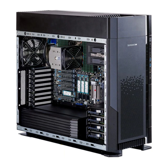
Page 12: Side View
Chapter 1: Introduction Side View chamber Peripheral Bays DIMMs U.2 Connectors PCIe 5.0 x16 Slots PCIe 5.0 x4 M.2 Slots 3.5" Drive Bays Power Supply Figure 1-4. System: Side View System Features: Side Feature Description Chamber Dedicated water cooling chamber for optional water cooling kit Supports Intel Xeon W-3400 Series processor up to 56 cores DIMMs 16x DDR5 ECC RDIMM slots, 4800MT/s (1DPC) / 4400MT/s (2DPC) -
Page 13: Motherboard Layout
Chapter 1: Introduction 1.3 Motherboard Layout Below is a layout of the X13SWA-TF motherboard with jumper, connector and LED locations shown. See the table on the following page for descriptions. For detailed descriptions, pinout information and jumper settings, refer to Chapter 4 or the Motherboard... -
Page 14: Quick Reference Table
Chapter 1: Introduction Quick Reference Table Jumper Description Default Setting JBT1 Clear CMOS (Onboard) Contact Pads to clear CMOS JPAC1 HD Audio Enable/Disable Pins 1-2 (Enabled) JPL1, JPL2 LAN1/LAN2 Enable/Disable Pins 1-2 (Enabled) JPME2 ME Manufacturing Mode Pins 1-2 (Normal) JPUSB1 USB8/9 Standby Power Pins 1-2 (Enabled) - Page 15 Front Access USB3.2 Gen. 2x2 Header (20Gb, Type C) VGA Port (through BMC) Note: For detailed instructions on how to configure VROC RAID settings, please refer to the VROC RAID Configuration User's Guide posted on the web page under the link: http://www. supermicro.com/support/manuals/.
-
Page 16: System Block Diagram
Chapter 1: Introduction System Block Diagram The block diagram below shows the connections and relationships between the subsystems and major components of the overall system. SVID VR14s PCIE_PE5 PCIe x16 SLOT #1 (112L only) PCIE_PE1 PCIe x16 SLOT #3 DIMMA1 DIMMA2 PCIE_PE6 PCIe x16 SLOT #4... -
Page 17: Chapter 2 Workstation Installation
PCBs by their edges and keep them in anti-static bags when not in use. 2.2 Unpacking the System Inspect the box in which the SuperWorkstation SYS-551A-T was shipped, and note if it was damaged in any way. If any equipment appears damaged, file a damage claim with the carrier who delivered it. -
Page 18: Workstation Precautions
Chapter 2: Workstation Installation Workstation Precautions • Review the electrical and general safety precautions in Appendix • Use a regulating uninterruptible power supply (UPS) to protect the workstation from power surges, voltage spikes and to keep your system operating in case of a power failure. •... -
Page 19: Chapter 3 Maintenance And Component Installation
Chapter 3: Maintenance and Component Installation Chapter 3 Maintenance and Component Installation This chapter provides instructions on installing and replacing main system components. To prevent compatibility issues, only use components that match the specifications and/or part numbers given. Installation or replacement of most components require that power first be removed from the system. -
Page 20: Accessing The System
Chapter 3: Maintenance and Component Installation 3.2 Accessing the System The CSE-GS7A-2000B chassis features a removable side cover for accessing the system need to remove power from the system as described in Section 3.1. Caution: Except for short periods of time, do not operate the system without the cover in place. -
Page 21: Front Bezel
Chapter 3: Maintenance and Component Installation Removing the Right Side Chassis Cover Begin by powering down the system. 1. Remove the two screws at the rear of the chassis. 2. Slide the cover back to remove it from the chassis. Figure 3-2. -
Page 22: Processor And Heatsink Installation
Thermal grease is pre-applied on a new heatsink. No additional thermal grease is needed. • Refer to the Supermicro website for updates on processor and memory support. • All graphics in this manual are for illustrations only. Your components may look different. -
Page 23: Overview Of The Processor Carrier Assembly
Chapter 3: Maintenance and Component Installation Overview of the Processor Carrier Assembly The processor carrier assembly includes a processor and a carrier as shown below: 1. Intel Xeon Processor Intel Xeon W-3400 series CPU (112L, XCC) 2. Processor Carrier = Cutout = Pin 1 = CPU Key = Cutout... -
Page 24: Overview Of The Cpu Socket
Chapter 3: Maintenance and Component Installation Overview of the CPU Socket The CPU socket is protected by a plastic protective cover. 1. Plastic Protective Cover 2. CPU Socket... -
Page 25: Overview Of The Processor Heatsink Module
Chapter 3: Maintenance and Component Installation Overview of the Processor Heatsink Module The Processor Heatsink Module (PHM) contains a heatsink, a processor carrier, and the Intel Xeon processor. 1. Heatsink with Thermal Grease 2. Processor Carrier 3. Intel Xeon Processor Processor Heatsink Module (PHM) -
Page 26: Creating The Processor Carrier Assembly
Chapter 3: Maintenance and Component Installation Creating the Processor Carrier Assembly To install a processor into the processor carrier, follow the steps below: 1. Before installation, make sure the lever on the processor carrier is pressed down as shown below. 2. -
Page 27: Assembling The Processor Heatsink Module
Chapter 3: Maintenance and Component Installation Assembling the Processor Heatsink Module After creating the processor carrier Processor Carrier Assembly assembly for the processor, mount it (Upside Down) onto the heatsink to create the processor heatsink module (PHM): Triangle on the CPU 1. -
Page 28: Preparing The Cpu Socket For Installation
Chapter 3: Maintenance and Component Installation Preparing the CPU Socket for Installation This motherboard comes with a plastic protective cover installed on the CPU socket. Remove it from the socket to install the Processor Heatsink Module (PHM). Gently pull up one corner of the plastic protective cover to remove it. -
Page 29: Installing The Processor Heatsink Module
Chapter 3: Maintenance and Component Installation Installing the Processor Heatsink Module After assembling the Processor Heatsink Module (PHM), install it onto the CPU socket: 1. Align pin 1 of the PHM with the printed triangle on the CPU socket. See the left image below. - Page 30 Chapter 3: Maintenance and Component Installation 6. Connect the fan power connector to a 4-pin fan header on the motherboard.
-
Page 31: Removing The Processor Heatsink Module
Chapter 3: Maintenance and Component Installation Removing the Processor Heatsink Module Before removing the processor heatsink module (PHM) from the motherboard, shut down the system and then unplug the AC power cord from all power supplies. Then follow the steps below: 1. -
Page 32: Memory Support And Installation
Chapter 3: Maintenance and Component Installation 3.4 Memory Support and Installation Note: Check the Supermicro website for recommended memory modules. Important: Exercise extreme care when installing or removing DIMM modules to prevent any possible damage. Memory Support For Intel Xeon W-3400 series processors (112L): supports up to 1TB of RDIMM and 4TB of 3DS RDIMM with speeds of up to 4800 MT/s (1DPC) and 4400 MT/s (2DPC) in 16 ECC DDR5 (288-pin) SMD DIMM slots. -
Page 33: Memory
Chapter 3: Maintenance and Component Installation 3.5 Memory General Guidelines for Optimizing Memory Performance • It is recommended to use DDR5 memory of the same type, size, and speed. • In a given channel, the black slot can be enabled only when the gray slot is populated first.. •... -
Page 34: Dimm Installation
Chapter 3: Maintenance and Component Installation DIMM Installation 1. Insert the desired number of DIMMs into the memory slots based on the recommended DIMM population tables in the previous section. Locate DIMM memory slots on the motherboard as shown on the left. X13SWA-TF REV:1.01 DESIGNED IN USA... -
Page 35: Motherboard Battery
Chapter 3: Maintenance and Component Installation 3.6 Motherboard Battery The motherboard uses non-volatile memory to retain system information when system power is removed. This memory is powered by a lithium battery residing on the motherboard. Replacing the Battery Begin by removing power from the system as described in Section 3.1. -
Page 36: Storage Drives
Chapter 3: Maintenance and Component Installation 3.7 Storage Drives Drive Cage The removable drive cage is accessed by removing the left chassis cover. These drives are not hot-swappable. Power must be removed from the system before removing or installing drives. The cage can house up to four drives of either 3.5" or 2.5" (2.5" drives require an optional bracket: MCP-220-73102-0N). -
Page 37: Installing Or Removing Drives
Chapter 3: Maintenance and Component Installation Installing or Removing Drives Installing Drive and Drive Tray 1. Using a tray that is compatible with the cage, install the drive onto the tray. 2. Install the drive and drive tray into the cage. Figure 3-6. -
Page 38: Top Front Peripheral Drive Bays
Chapter 3: Maintenance and Component Installation Top Front Peripheral Drive Bays Two 5.25" peripheral tool-less drive bays are located at the top front of the chassis. These drives are not hot-swap, power must be removed from the system before removing or installing drives. -
Page 39: Front Side Drive Bays
Chapter 3: Maintenance and Component Installation Front Side Drive Bays Two 2.5" drive bays are included along the front right side of the chassis. These drives are not hot-swap, power must be removed from the system before removing or installing drives. Installing/Removing the Front Side Drive Bays Begin by powering down the system. -
Page 40: Installing And Removing Drives From Trays
Chapter 3: Maintenance and Component Installation Installing and Removing Drives from Trays The drives must be inserted into tool-less drive trays before being installed in the system. Installing a Drive into a Drive Tray 1. Pull out the two securing tabs on the tray as illustrated below. 2. -
Page 41: Installation
M.2 device. Note 1: Please use wide temperature (up to 85°C) M.2 devices for M.2-C4 and M.2-C3. Note 2: It is strongly recommended that you install a Supermicro M.2 heatsink (p/n SNK-C0156L) on the M.2 device as described in next section. -
Page 42: Heatsink Installation (Optional)
Chapter 3: Maintenance and Component Installation M.2 Heatsink Installation (Optional) 1. Remove the thermal pad protective films from the cover and the tray of the M.2 heatsink. Heatsink Cover Heatsink Tray 2. Place the M.2 device into the tray, and then put the heatsink cover in place. Be careful to align the holes on the tray with the holes on the cover. -
Page 43: 2280 M.2 Device Installation
3. Insert the M.2 device or the heatsink assembly into the M.2 socket at a 30-degree angle and and press it down. Standard M.2 M.2 with Supermicro heatsink 4. Tighten the standoff screw to secure the M.2 device or the heatsink assembly into place. Do not overtighten so as to avoid damaging the M.2 device. -
Page 44: 22110 M.2 Device Installation
2. Insert the M.2 device or the heatsink assembly into the M.2 socket at a 30-degree angle and press it down. Standard M.2 M.2 with Supermicro heatsink 3. Tighten the standoff screw to secure the M.2 device or the heatsink assembly into place. Do not overtighten so as to avoid damaging the M.2 device. -
Page 45: Installing Gpus
Chapter 3: Maintenance and Component Installation Installing GPUs Installing a GPU with Bracket and Holder 1. Align the screw holes of the GPU with the bracket by standing the gold finger on the surface. 2. Tighten two screws to secure the GPU to the bracket. Figure 3-13. - Page 46 Chapter 3: Maintenance and Component Installation Figure 3-15. Remove the PCIe Bracket Figure 3-16. Installing the GPU to the Motherboard...
- Page 47 Chapter 3: Maintenance and Component Installation Lock Figure 3-17. Locking the GPU 7. Install the GPU plastic cover and the left side cover. Figure 3-18. Installing the GPU Plastic Cover...
-
Page 48: System Cooling
Chapter 3: Maintenance and Component Installation 3.8 System Cooling The chassis includes two front intake fans and one rear exhaust fan. The top of the chassis can accommodate up to three optional 12-cm fans for three more GPU cards installation or an optional liquid cooling unit. - Page 49 Chapter 3: Maintenance and Component Installation 4. With the cover removed, remove all screws that secure the top panel to the chassis. Lift the top panel up and out of the chassis. 5. If necessary, disconnect the wiring of the failed fan, then replace it with a new fan and reconnect the wiring.
- Page 50 Chapter 3: Maintenance and Component Installation Replacing Front Fans 1. Open the front bezel to access the front fan area. 2. Disconnect the fan wiring. 3. If existing fans are mounted with rubber pins, pull the fans toward you. If the fans are mounted by screws, unscrew the fans.
- Page 51 Chapter 3: Maintenance and Component Installation Replacing the Rear Fan 1. Open the left side cover for access to the rear fan. 2. Remove the screws at the top back of the chassis that secure the fan to the chassis. 3.
-
Page 52: Liquid Cooling
Chapter 3: Maintenance and Component Installation Liquid Cooling The GS7 may be outfitted with a liquid cooling system that installs in the top panel. Installing a Liquid Cooling Unit 1. Begin by removing the screw from the top chassis cover. 2. -
Page 53: Installing Expansion Cards
Chapter 3: Maintenance and Component Installation 3.9 Installing Expansion Cards Installing an Expansion Card 1. Power down the system as described in Section 3.1. 2. Remove the left chassis cover. 3. Push in the long release tab on the right side and the small one on the left side of the cover to detach and remove the cover completely. -
Page 54: Power Supply
Chapter 3: Maintenance and Component Installation 3.10 Power Supply The SYS-551A-T chassis supports a power supply on the rear floor of the chassis. It is recommended that the power requirements of installed components in the system total no more than 80% of the power supply rating. The 2000W power supply that comes standard with the SYS-551A-T a modular type power supply that allows you to connect only the wiring you need for your system's configuration. -
Page 55: Chapter 4 Motherboard Connections
Chapter 4: Motherboard Connections Chapter 4 Motherboard Connections This section describes the connections on the motherboard and provides pinout definitions. Note that depending on how the system is configured, not all connections are required. The LEDs on the motherboard are also described here. A motherboard layout indicating component locations may be found in Chapter 1. - Page 56 Chapter 4: Motherboard Connections (Continued from the previous page) Important: To provide adequate power supply to the motherboard, be sure to connect the 24-pin ATX power connector and the required 8-pin power connectors to the power supply. Failure to do so may void the manufacturer warranty on your power supply and motherboard. When installing multiple GPU cards, you can refer to the table below to connect the required 8-pin connectors (JPW2, JPW3, and JPW4) to the power supply.
-
Page 57: Headers And Connectors
Chapter 4: Motherboard Connections 4.2 Headers and Connectors Fan Headers There are ten 4-pin fan headers (FAN1 - FAN6 and FANA - FAND) on the motherboard. All these 4-pin fan headers are backwards compatible with the traditional 3-pin fans. However, fan speed control is available for 4-pin fans only by Thermal Management via the IPMI 2.0 interface. - Page 58 Chapter 4: Motherboard Connections Front Panel Audio Header A 10-pin audio header (AUDIO FP) located on the motherboard allows you to use the onboard sound chip (ALC888S) for audio function. Connect an audio cable to this header to use this feature.
- Page 59 The JTPM1 header is used to connect a Trusted Platform Module (TPM)/Port 80, which is available from Supermicro (optional). A TPM/Port 80 header is a security device that supports encryption and authentication in hard drives. It allows the motherboard to deny access if the TPM associated with the hard drive is not installed in the system.
- Page 60 Chapter 4: Motherboard Connections Standby Power The Standby Power header is located at JSTBY1 on the motherboard. You must have a card with a Standby Power connector and a cable to use this feature. Refer to the table below for pin definitions. Standby Power Pin Definitions Pin#...
- Page 61 Chapter 4: Motherboard Connections Power SMB (I C) Header The Power System Management Bus (I C) connector (JPI2C1) monitors the power supply, fan, and system temperatures. Refer to the table below for pin definitions. Power SMB Header Pin Definitions Pin# Definition Clock Data...
-
Page 62: Control Panel
These connectors are designed specifically for use with Supermicro chassis. Refer to the figure below for the descriptions of the front control panel buttons and LED indicators. - Page 63 Chapter 4: Motherboard Connections Power On & BMC/BIOS Status LED Button The Power On and BMC/BIOS Status LED button is located on pins 1 and 2 of JF1. Momentarily contacting both pins will power on/off the system or display BMC/BIOS status. Refer to the tables below for more information.
- Page 64 Chapter 4: Motherboard Connections NIC1/NIC2 (LAN1/LAN2) The Network Interface Controller (NIC) LED connection for LAN port 1 is located on pins 11 and 12 of JF1, and LAN port 2 is on pins 9 and 10. Attach the NIC LED cables here to display network activity.
-
Page 65: Rear I/O Ports
Chapter 4: Motherboard Connections 4.3 Rear I/O Ports See Figure 4-2 below for the locations and descriptions of the I/O ports on the rear of the motherboard. LAN2 LAN1 HD AUDIO USB10 USB6/7 USB8/9 COM1 USB2/3 JUIDB1 (USB3.2 Gen 2X2) (USB3.2 Gen 2x1) (USB3.2 Gen 2x1) LED4... - Page 66 Chapter 4: Motherboard Connections Back Panel High Definition Audio (HD Audio) This motherboard features a 7.1+2 Channel High Definition Audio (HDA) codec that provides 10 DAC channels. The HD Audio connections simultaneously support multiple-streaming 7.1 sound playback with two channels of independent stereo output through the front panel stereo out for front, rear, center, and subwoofer speakers.
- Page 67 Chapter 4: Motherboard Connections Universal Serial Bus (USB) Connections The motherboard provides the following USB ports on the rear I/O panel: • Four USB3.2 Gen2 ports (USB6, USB7, USB8, USB9) • One USB 3.2 Gen2 x2 port (USB10) • Two USB2.0 ports (USB2/3) The motherboard also provides the following headers for front accessible USB connections with a cable (not provided): •...
- Page 68 BMC on the motherboard. For more details on the UID LEDs and BMC LEDs, refer to the tables on next page. Also, refer to the BMC User's Guide posted on our website at http://www.supermicro.com for more information on BMC. UID/BMC Reset Switch (JUIDB1) Features &...
-
Page 69: Jumpers
Chapter 4: Motherboard Connections 4.4 Jumpers How Jumpers Work To modify the operation of the motherboard, jumpers can be used to choose between optional settings. Jumpers create shorts between two pins to change the function of the connector. Pin 1 is identified with a square solder pad on the printed circuit board. See the diagram below for an example of jumping pins 1 and 2. - Page 70 Chapter 4: Motherboard Connections LAN Port Enable/Disable JPL1 and JPL2 allow you to enable the onboard LAN ports (LAN1 and LAN2). The default setting is pins 1-2 to enable the connections. Refer to the table below for jumper settings. LAN1/LAN2 Enable/Disable Jumper Settings Jumper Setting Definition...
- Page 71 Chapter 4: Motherboard Connections Watchdog Watchdog (JWD1) is a system monitor that can reboot the system when a software application hangs. Close pins 1-2 to reset the system if an application hangs. Close pins 2-3 to generate a non-maskable interrupt (NMI) signal for the application that hangs. Refer to the table below for jumper settings.
-
Page 72: Led Indicators
Status Code LED LED8 is an alphanumeric display with two LED digits to provide the status or POST code when the motherboard is powered on. Please download the following AMI publication for a complete list of POST codes: https://www.supermicro.com/manuals/other/AMI_AptioV_BIOS_POST_ Codes_for_SM_Motherboards.pdf... -
Page 73: Chapter 5 Software
Chapter 5 Software 5.1 Driver Installation The Supermicro website that contains drivers and utilities for your system is at https://www. supermicro.com/wdl/driver. Some of these must be installed, such as the chipset driver. After accessing the website, go into the CDR_Images (in the parent directory of the above link) and locate the ISO file for your motherboard. -
Page 74: Superdoctor® 5
5.2 SuperDoctor ® The Supermicro SuperDoctor 5 is a program that functions in a command-line or web-based interface for Windows and Linux operating systems. The program monitors such system health information as CPU temperature, system voltages, system power consumption, fan speed, and provides alerts via email or Simple Network Management Protocol (SNMP). -
Page 75: Ipmi
When logging in to the BMC for the first time, please use the unique password provided by Supermicro to log in as an administrator. After loggin in, you can change the administrator password to protect your security. When logging in as an administrator, you can also create a user account and set the password of your choice for subsequent logins. -
Page 76: Chapter 6 Troubleshooting And Support
Chapter 7: Troubleshooting and Support Chapter 6 Troubleshooting and Support 6.1 Information Resources Website A great deal of information is available on the Supermicro website, www.supermicro.com. Products Figure 6-1. Supermicro Website • Specifications for workstations and other hardware are available by clicking on Products. -
Page 77: Baseboard Management Controller (Bmc)
Security Center for recent security notices Supermicro Phone and Addresses 6.2 Baseboard Management Controller (BMC) The system supports the Baseboard Management Controller (BMC). BMC is used to provide remote access, monitoring, and management. There are several BIOS settings that are related to BMC. -
Page 78: Troubleshooting Procedures
Chapter 7: Troubleshooting and Support 6.3 Troubleshooting Procedures Use the following procedures to troubleshoot your system. If you have followed all of the procedures below and still need assistance, refer to the ‘Technical Support Procedures’ or ‘Returning Merchandise for Service’ section(s) in this chapter. Always disconnect the AC power cord before adding, changing or installing any non hot-swap hardware components. -
Page 79: System Boot Failure
Chapter 7: Troubleshooting and Support System Boot Failure If the system does not display Power-On-Self-Test (POST) or does not respond after the power is turned on, check the following: 1. Check for any error beep from the motherboard speaker. • If there is no error beep, try to turn on the system without DIMM modules installed. -
Page 80: When The System Becomes Unstable
Chapter 7: Troubleshooting and Support When the System Becomes Unstable A. If the system becomes unstable during or after OS installation, check the following: 1. CPU/BIOS support: Make sure that your CPU is supported and that you have the latest BIOS installed in your system. -
Page 81: Technical Support Procedures
Before contacting Technical Support, please take the following steps. Also, please note that as a motherboard manufacturer, Supermicro also sells motherboards through its channels, so it is best to first check with your distributor or reseller for troubleshooting services. They should know of any possible problems with the specific system configuration that was sold to you. -
Page 82: Frequently Asked Questions
BIOS revision to make sure that it is newer than your BIOS before downloading. Note: The SPI BIOS chip used on this motherboard cannot be removed. Send your motherboard back to our RMA Department at Supermicro for repair. For BIOS Recovery instructions, please refer to the AMI BIOS Recovery Instructions posted at http://www. - Page 83 Chapter 7: Troubleshooting and Support 4. The FLASH.NSH script will compare the Flash Descriptor Table (FDT) code in the new BIOS with the existing one in the motherboard: a. If a different FDT is found • A new file, STARTUP.NSH, will be created, and the system will automatically reboot in 10 seconds without you pressing any key.
-
Page 84: Battery Removal And Installation
Chapter 7: Troubleshooting and Support 6.6 Battery Removal and Installation Battery Removal To remove the onboard battery, follow the steps below: 1. Power off your system and unplug your power cable. 2. Locate the onboard battery as shown below. 3. Use a tool such as a pen or a small screwdriver, push the battery lock outwards to unlock it. -
Page 85: Returning Merchandise For Service
During the warranty period, contact your distributor first for any product problems. 6.8 Feedback Supermicro values your feedback as we strive to improve our customer experience in all facets of our business. Please email us at techwriterteam@supermicro.com to provide feedback on... -
Page 86: Contacting Supermicro
San Jose, CA 95131 U.S.A. Tel: +1 (408) 503-8000 Fax: +1 (408) 503-8008 Email: marketing@supermicro.com (General Information) Sales-USA@supermicro.com (Sales Inquiries) Government_Sales-USA@supermicro.com (Gov. Sales Inquiries) support@supermicro.com (Technical Support) RMA@supermicro.com (RMA Support) Webmaster@supermicro.com (Webmaster) Website: www.supermicro.com Europe Address: Super Micro Computer B.V. -
Page 87: Appendix A Standardized Warning Statements For Ac Systems
Supermicro's Technical Support department for assistance. Only certified technicians should attempt to install or configure components. Read this appendix in its entirety before installing or configuring components in the Supermicro chassis. These warnings may also be found on our website at http://www.supermicro.com/about/... - Page 88 Appendix A: Standardized Warning Statements for AC Systems Warnung WICHTIGE SICHERHEITSHINWEISE Dieses Warnsymbol bedeutet Gefahr. Sie befinden sich in einer Situation, die zu Verletzungen führen kann. Machen Sie sich vor der Arbeit mit Geräten mit den Gefahren elektrischer Schaltungen und den üblichen Verfahren zur Vorbeugung vor Unfällen vertraut. Suchen Sie mit der am Ende jeder Warnung angegebenen Anweisungsnummer nach der jeweiligen Übersetzung in den übersetzten Sicherheitshinweisen, die zusammen mit diesem Gerät ausgeliefert wurden.
- Page 89 Appendix A: Standardized Warning Statements for AC Systems . ٌ ا ك ً ف حالة و ٌ يك أى تتسبب ف اصابة جسذ ة ٌ هذا الزهز ع ٌ خطز !تحذ ز قبل أى تعول عىل أي هعذات،يك عىل علن بالوخاطز ال ا ٌجوة عي الذوائز ٍ...
- Page 90 Appendix A: Standardized Warning Statements for AC Systems Warnung Vor dem Anschließen des Systems an die Stromquelle die Installationsanweisungen lesen. ¡Advertencia! Lea las instrucciones de instalación antes de conectar el sistema a la red de alimentación. Attention Avant de brancher le système sur la source d'alimentation, consulter les directives d'installation. .יש...
- Page 91 Appendix A: Standardized Warning Statements for AC Systems Warnung Dieses Produkt ist darauf angewiesen, dass im Gebäude ein Kurzschluss- bzw. Überstromschutz installiert ist. Stellen Sie sicher, dass der Nennwert der Schutzvorrichtung nicht mehr als: 250 V, 20 A beträgt. ¡Advertencia! Este equipo utiliza el sistema de protección contra cortocircuitos (o sobrecorrientes) del edificio.
- Page 92 Appendix A: Standardized Warning Statements for AC Systems Power Disconnection Warning Warning! The system must be disconnected from all sources of power and the power cord removed from the power supply module(s) before accessing the chassis interior to install or remove system components. 電源切断の警告...
- Page 93 Appendix A: Standardized Warning Statements for AC Systems אזהרה מפני ניתוק חשמלי !אזהרה יש לנתק את המערכת מכל מקורות החשמל ויש להסיר את כבל החשמלי מהספק .לפני גישה לחלק הפנימי של המארז לצורך התקנת או הסרת רכיבים يجب فصم اننظاو من جميع مصادر انطاقت وإ ز انت سهك انكهرباء من وحدة امداد انطاقت...
- Page 94 Appendix A: Standardized Warning Statements for AC Systems Attention Il est vivement recommandé de confier l'installation, le remplacement et la maintenance de ces équipements à des personnels qualifiés et expérimentés. !אזהרה .צוות מוסמך בלבד רשאי להתקין, להחליף את הציוד או לתת שירות עבור הציוד واملدربيه...
- Page 95 Appendix A: Standardized Warning Statements for AC Systems Warnung Diese Einheit ist zur Installation in Bereichen mit beschränktem Zutritt vorgesehen. Der Zutritt zu derartigen Bereichen ist nur mit einem Spezialwerkzeug, Schloss und Schlüssel oder einer sonstigen Sicherheitsvorkehrung möglich. ¡Advertencia! Esta unidad ha sido diseñada para instalación en áreas de acceso restringido. Sólo puede obtenerse acceso a una de estas áreas mediante la utilización de una herramienta especial, cerradura con llave u otro medio de seguridad.
- Page 96 Appendix A: Standardized Warning Statements for AC Systems Battery Handling Warning! There is the danger of explosion if the battery is replaced incorrectly. Replace the battery only with the same or equivalent type recommended by the manufacturer. Dispose of used batteries according to the manufacturer's instructions 電池の取り扱い...
- Page 97 Appendix A: Standardized Warning Statements for AC Systems هناك خطر من انفجار يف حالة اسحبذال البطارية بطريقة غري صحيحة فعليل اسحبذال البطارية فقط بنفس النىع أو ما يعادلها مام أوصث به الرشمة املصنعة جخلص من البطاريات املسحعملة وفقا لحعليامت الرشمة الصانعة 경고! 배터리가...
- Page 98 Appendix A: Standardized Warning Statements for AC Systems ¡Advertencia! Puede que esta unidad tenga más de una conexión para fuentes de alimentación. Para cortar por completo el suministro de energía, deben desconectarse todas las conexiones. Attention Cette unité peut avoir plus d'une connexion d'alimentation. Pour supprimer toute tension et tout courant électrique de l'unité, toutes les connexions d'alimentation doivent être débranchées.
- Page 99 Appendix A: Standardized Warning Statements for AC Systems Backplane Voltage Warning! Hazardous voltage or energy is present on the backplane when the system is operating. Use caution when servicing. バックプレーンの電圧 システムの稼働中は危険な電圧または電力が、 バックプレーン上にかかっています。 修理する際には注意く ださい。 警告 当系统正在进行时,背板上有很危险的电压或能量,进行维修时务必小心。 警告 當系統正在進行時,背板上有危險的電壓或能量,進行維修時務必小心。 Warnung Wenn das System in Betrieb ist, treten auf der Rückwandplatine gefährliche Spannungen oder Energien auf.
- Page 100 Appendix A: Standardized Warning Statements for AC Systems هناك خطز مه التيار الكهزبايئ أوالطاقة املىجىدة عىل اللىحة عندما يكىن النظام يعمل كه حذ ر ا عند خدمة هذا الجهاس 경고! 시스템이 동작 중일 때 후면판 (Backplane)에는 위험한 전압이나 에너지가 발생 합니다. 서비스...
- Page 101 Appendix A: Standardized Warning Statements for AC Systems תיאום חוקי החשמל הארצי !אזהרה .התקנת הציוד חייבת להיות תואמת לחוקי החשמל המקומיים והארציים تركيب املعدات الكهربائية يجب أن ميتثل للقىاويه املحلية والىطىية املتعلقة بالكهرباء 경고! 현 지역 및 국가의 전기 규정에 따라 장비를 설치해야 합니다. Waarschuwing Bij installatie van de apparatuur moet worden voldaan aan de lokale en nationale elektriciteitsvoorschriften.
- Page 102 Appendix A: Standardized Warning Statements for AC Systems Attention La mise au rebut ou le recyclage de ce produit sont généralement soumis à des lois et/ou directives de respect de l'environnement. Renseignez-vous auprès de l'organisme compétent. סילוק המוצר !אזהרה .סילוק סופי של מוצר זה חייב להיות בהתאם להנחיות וחוקי המדינה التخلص...
- Page 103 Appendix A: Standardized Warning Statements for AC Systems Warnung Gefährlich Bewegende Teile. Von den bewegenden Lüfterblätter fern halten. Die Lüfter drehen sich u. U. noch, wenn die Lüfterbaugruppe aus dem Chassis genommen wird. Halten Sie Finger, Schraubendreher und andere Gegenstände von den Öffnungen des Lüftergehäuses entfernt.
- Page 104 Verbindungskabeln, Stromkabeln und/oder Adapater, die Ihre örtlichen Sicherheitsstandards einhalten. Der Gebrauch von anderen Kabeln und Adapter können Fehlfunktionen oder Feuer verursachen. Die Richtlinien untersagen das Nutzen von UL oder CAS zertifizierten Kabeln (mit UL/CSA gekennzeichnet), an Geräten oder Produkten die nicht mit Supermicro gekennzeichnet sind.
- Page 105 .قيرح وأ لطع يف ببستي دق ىرخأ تالوحمو تالباك يأ مادختسا .ميلسلا سباقلاو لصوملا مجح لبق نم ةدمتعملا تالباكلا مادختسا تادعملاو ةيئابرهكلا ةزهجألل ةمالسلا نوناق رظحيUL وأCSA ( ةمالع لمحت يتلاوUL/CSA) لبق نم ةددحملاو ةينعملا تاجتنملا ريغ ىرخأ تادعم يأ عمSupermicro.
- Page 106 사항을 준수하여 제공되거나 지정된 연결 혹은 구매 케이블, 전원 케이블 및 AC 어댑터를 사용하십시오. 다른 케이블이나 어댑터를 사용하면 오작동이나 화재가 발생할 수 있습니다. 전기 용품 안전법은 UL 또는 CSA 인증 케이블 (코드에 UL / CSA가 표시된 케이블)을 Supermicro 가 지정한 제품 이외의 전기 장치에 사용하는 것을 금지합니다. Stroomkabel en AC-Adapter...
-
Page 107: Appendix B System Specifications
Appendix B: System Specifications Appendix B System Specifications Processors Supports a single Intel Xeon W-3400 Series processor (Socket E1, LGA4677), with up to 56 cores and a TDP of up to 350W. Note: 4th Gen Intel® Xeon® Scalable processors are not supported in this system. Chipset Intel PCH W790 BIOS... - Page 108 Appendix B: System Specifications Input/Output Front: Two USB2.0 ports Two USB3.2 Gen1 (5G) Type A ports One USB3.2 Gen2 (10G) Type C port One Power Button One Audio In One Mic In One LED on/off Button Rear: One 10Gb LAN port One 1Gb LAN port One USB3.2 Gen2 x2 (20Gbps) Type C port Four USB3.2 Gen2 x1 ports...
- Page 109 Appendix B: System Specifications Regulatory Compliance FCC, ICES, CE, VCCI, CSA/ UL, CB, UKCA, RCM Applied Directives, Standards EMC/EMI: 2014/30/EU (EMC Directive) CLASS B Electromagnetic Compatibility Regulations 2016 FCC Part 15 Subpart B ICES-003 VCCI-CISPR 32 AS/NZS CISPR 32 BS/EN 55032 BS/EN 55035 CISPR 32 CISPR 35...
Need help?
Do you have a question about the SuperWorkstation SYS-551A-T and is the answer not in the manual?
Questions and answers