Table of Contents
Advertisement
Advertisement
Table of Contents

Related Manuals for Dahua DHI-VTO2311R-WP


Summary of Contents for Dahua DHI-VTO2311R-WP
- Page 1 Villa Door Station Quick Start Guide V1.0.2...
-
Page 2: Foreword
Quick Start Guide Foreword General This manual introduces the installation, functions and operations of the Villa Door Station (hereinafter referred to as "the VTO"). Read carefully before using the device, and keep the manual safe for future reference. Safety Instructions The following signal words might appear in the manual. - Page 3 Quick Start Guide ● The manual will be updated according to the latest laws and regulations of related jurisdictions. For detailed information, see the paper user’s manual, use our CD-ROM, scan the QR code or visit our official website. The manual is for reference only. Slight differences might be found between the electronic version and the paper version.
- Page 4 Quick Start Guide Important Safeguards and Warnings This section introduces content covering the proper handling of the device, hazard prevention, and prevention of property damage. Read carefully before using the device, and comply with the guidelines when using it. Operation Requirements ●...
-
Page 5: Table Of Contents
Table of Contents Foreword ................................I Important Safeguards and Warnings ......................III 1 Structure ................................ 1 Villa Door Station (multiple buttons) ..........................1 1.1.1 Front Panel ..................................1 1.1.2 Rear Panel ..................................2 Villa Door Station (single button) ............................3 1.2.1 Front Panel .................................. -
Page 6: Structure
Quick Start Guide Structure Villa Door Station (Multiple Buttons) 1.1.1 Front Panel Front panel Table 1-1 Components Name Function Audio input. Provide a constant light to focus more easily on a Illuminator subject in dark surroundings. Camera Capture images or record videos for the VTO. Call buttons Call the VTH. -
Page 7: Rear Panel
Quick Start Guide 1.1.2 Rear Panel The function ports might differ depending on the model you use. Rear panel Table 1-2 Components Name Function Used to insert SD card so that data information such as SD card slot images and videos can be stored. Alarm port, door detector port, 485 port, power port Functional ports and etc. -
Page 8: Villa Door Station (Single Button)
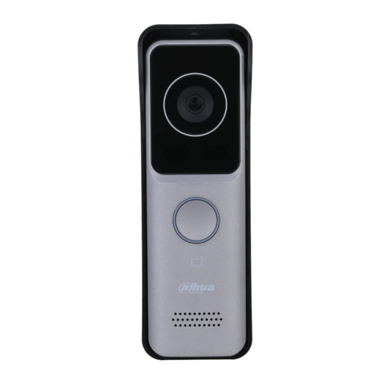
Quick Start Guide Functional port Port description Villa Door Station (Single Button) 1.2.1 Front Panel There are different models with different front panel. Differences in size and appearance are found depending on your model. - Page 9 Quick Start Guide Front panel Table 1-3 Description of front panels Name Function Audio input. Camera Capture images or record videos for the VTO. Call button Call the VTH. Swipe the registered cards to unlock doors. Card swiping area The card swiping function is only supported by some models.
-
Page 10: Rear Panel
Quick Start Guide 1.2.2 Rear Panel The function ports might differ depending on the model. Here are two models used as examples. Rear panel (1) Table 1-4 Description of rear panel Name Function Network port Used to connect to the network. Used to insert SD card so that data information such as SD card slot images and videos can be stored. - Page 11 Quick Start Guide Rear panel (2) Table 1-5 Description of real panel Name Function Used to insert SD card so that data information such as SD card slot images and videos can be stored. Power port Used to connect to the power supply. Press and hold the button for several seconds to do Reset button factory reset.
-
Page 12: Button Model
Quick Start Guide Button Model 1.3.1 Front Panel Front panel Table 1-6 Description of front panel Name Function The button model can be connected to the VTH. Press Press button the button on the model and the VTH receives an alarm signal. -
Page 13: Rear Panel
Quick Start Guide 1.3.2 Rear Panel Rear panel Table 1-7 Description of rear panel Name Function Function port Used for alarm input. - Page 14 Quick Start Guide Table 1-8 Cable connection Connect the KEY port of the button model to any one of the alarm input ports of the indoor monitor (VTH) with a cable thread. After that, tap Setting > Alarm > Wired Zone on the VTH and set the Type of the alarm input port you chose to connect to the KEY port as Doorbell.
-
Page 15: Installation
Quick Start Guide Installation Preparations This chapter introduces precautions in installation. For detailed steps, see the corresponding installation guide. ● Do not expose the VTO to condensation, high temperature, direct sunlight, stain, dust, and chemically corrosive substances. ● Installation should be done by professional teams. Do not dismantle or repair the VTO by yourself in case of device failure. -
Page 16: Villa Door Station (Single Button)
Quick Start Guide Installation If you do not want to install the rain cover, you could use the sticker included in the package to cover the screw hole. 2.2.2 Villa Door Station (Single Button) Here are examples of two model’s installation, depending on differences in model dimensions. Model Example 1 Step 1 Open the port cover of the VTO, drill screw holes on the wall according to the dimension of the mounting hole on the rear panel of the VTO. - Page 17 Quick Start Guide Dimension (mm [inch]) Installation (cover port) Installation (bracket)
- Page 18 Quick Start Guide Model Example 2 Step 1 Open the port cover of the VTO, drill screw holes on the wall according to the dimension of the mounting hole on the rear panel of the VTO. Step 2 Complete the cable wiring. Step 3 Fix the port cover or the bracket to the rear panel of the VTO with four screws.
-
Page 19: Button Model
Quick Start Guide Installation (bracket) 2.2.3 Button Model Step 1 Open the port cover of the button model, drill screw holes on the wall according to the dimension of the mounting hole on the rear panel of the button model. Step 2 Complete the cable wiring. - Page 20 Quick Start Guide Installation (port cover) Installation (bracket)
-
Page 21: Configuration
Quick Start Guide Configuration This chapter provides a step-by-step configuration of the VTO, as well as how to register digital indoor monitors (hereinafter referred to as the "VTH") to the VTO to realize its intercom function. Follow the instructions below to get started. ●... - Page 22 Quick Start Guide Device initialization Select the Email checkbox and enter an email address. Step 4 This helps you to reset your password when your password is lost. Set an email address Step 5 Click Next.
-
Page 23: Dmss App
Quick Start Guide Initialization successful Step 6 Click OK. Enter the username (admin by default) and the new password to log in to the web page. Login page 3.1.2 DMSS APP If your VTO model only supports Wi-Fi connection to the network, you can only initialize the VTO on the DMSS app. - Page 24 Quick Start Guide The hotspot function is to enable you connect the VTO to the network through AP configuration on the app. Step 3 Add the VTO to the DMSS app. On the Home screen, tap , and then select SN/Scan. Add a VTO.
- Page 25 Quick Start Guide Step 4 Complete initialization based on instructions on the app. Enter the password you planned for the VTO, and confirm it, and then tap Next. Select Cloud Access and Auto-check, and then tap OK. The initialization process is completed. Initialization Step 5 Connect the VTO to the network through Wi-Fi.
- Page 26 Quick Start Guide Configure device name Step 7 View monitoring video from the camera on the VTO. Monitoring...
-
Page 27: Configuring Network Parameters
Quick Start Guide Configuring Network Parameters You need to configure the TCP/IP information to connect the VTO to the network. The descriptions below are for models with a Wireless LAN card. A Wireless LAN device is optional. Wireless LAN Step 1 Log in to the web page of the VTO. Step 2 Select Network >... -
Page 28: Configuring Sip Servers
Quick Start Guide Configuring SIP Servers When connected to the same SIP server, VTOs and VTHs can call each other. You can use a VTO or a platform as the SIP server. We recommend you use a VTO as the SIP server in the villa scenario. Step 1 Log in to the web page of the VTO. -
Page 29: Configuring Vto Numbers
Quick Start Guide Table 3-2 Parameter description Parameter Description IP Address The IP address that you planned for the VTO. Port 5060 by default when a VTO works as SIP server. SIP Domain Leave it as default. Username/Password Used to log in to the web page of the VTO. SIP Server Username/ Used to log in to the SIP server. -
Page 30: Adding Vtos
Quick Start Guide Device properties Step 3 Configure the parameters. Table 3-3 Parameter description Parameter Description Device Type Villa Station. Device Name The name you planned for your VTO. You could keep it null. Villa Call No. Used to call VTHs. It should contain no more than 9 numbers. Center Call No. - Page 31 Quick Start Guide VTO No. Management Step 4 Configure the parameters. Add VTOs Table 3-4 Parameters Parameter Description Rec No. The room number of the VTO. Register Password Keep it by default. Build No. Keep them null when the VTO serves as the SIP server. The two parameters are only applicable when the platform works as the SIP server.
-
Page 32: Adding Vth Room Number
Quick Start Guide Adding VTH Room Number When VTO serves as the SIP server, you can add VTH into the main VTO to achieve intercom functions. Step 1 Log in to the web page of the VTO. Step 2 Select Household Setting > VTH Management. VTH Management Select Add to register new VTH onto the main VTO. -
Page 33: Binding Vth Room Numbers (For Certain Models Only)
Quick Start Guide Parameters Description The room number can contain 6 digits of numbers of letters or their combination at most, and it cannot be the same as any VTO number. Room No. When there are multiple VTHs, the room number for the main VTH ... - Page 34 Quick Start Guide White module Room list Step 5 Click Save to save the selected room number. Step 6 Click Confirm to save all the settings. Confirm...
-
Page 35: Issuing Cards
Quick Start Guide Issuing Cards Issue an access card to unlock the door of a room. To use this function, the VTO must have a card reader. Step 1 Log in to the web page of the VTO. Step 2 Select Household Setting > Personnel Management. Personnel management Step 3 Click Add. - Page 36 Quick Start Guide Operation succeed Step 5 Select to go to the card issuing window. For some VTO models, the QR code is embedded in the Personnel Management page. Yet for some models, you need to go to Network > Basic > Cloud Service to check the QR code. Card issuing window Step 6 Click Issue Card to issue cards.
- Page 37 Quick Start Guide Countdown in process Step 8 Click Confirm Send Card after swiping to complete the issuing process. Information of the newly issued card Other Operations Click to set it to loss, and then the icon changes to . The lost card cannot be used to open ...
-
Page 38: Commissioning
Quick Start Guide Commissioning After the basic configuration is complete, check whether the intercom communication works. VTO Calling VTH Once the VTO and VTH are connected, the duel communication function is enabled. Step 1 Dial a room number (for example, 9901) on the VTO. Step 2 to answer the call on the VTH. - Page 39 Quick Start Guide Figure 4-2 Door Figure 4-3 Monitoring...
-
Page 40: Cybersecurity Recommendations
Quick Start Guide Cybersecurity Recommendations Mandatory actions to be taken for basic equipment network security: 1. Use Strong Passwords Please refer to the following suggestions to set passwords: ● The length should not be less than 8 characters. ● Include at least two types of characters; character types include upper and lower case letters, numbers and symbols. - Page 41 Quick Start Guide We recommend you to bind the IP and MAC address of the gateway to the equipment, thus reducing the risk of ARP spoofing. 8. Assign Accounts and Privileges Reasonably According to business and management requirements, reasonably add users and assign a minimum set of permissions to them.
- Page 42 Quick Start Guide...
Need help?
Do you have a question about the DHI-VTO2311R-WP and is the answer not in the manual?
Questions and answers