
Related Manuals for Master Water Conditioning MP-NS-30T


Summary of Contents for Master Water Conditioning MP-NS-30T
- Page 1 MASTER Water Conditioning Corp. www.masterwater.com Installation and Operation Manual MP-NS-30T/40T with the 268/762 Logix Control Valve April 2006...
- Page 2 Table of Contents Page Topic Description Model # and Packaging Packaging Information Component Packaging Packaging Description Description MP-MBA Logix Control Valve Valve Description Combination Unit System Positioning Combination Unit Tank Loading Filling with Media Logix 268/762 Control Valve Attaching Valve to Tank Figure 1 &...
- Page 3 Installation and Operating Instructions for 268/762 Logix Top Mount Combination Unit Model #: ____ MP-NS-30T Acid Neutralizer and Softener ____ MP-NS-40T Acid Neutralizer and Softener Shipping Carton Description / unit: # of Contents Description cartons Mineral tank Distributor pipe installed Brine tank 464 shutoff valve assembly.
- Page 4 Combination Unit Positioning: 1. Place combination unit in desired position, far enough from walls and other obstructions to allow for servicing the unit. 2. Place the combination unit within reasonable access to a grounded 115V/60 HZ circuit and a legal drain line connection. Combination Unit Tank Loading: 1.
- Page 5 Logix Control Valve: 1. When facing the front of the Logix timer, the inlet connection is located on the left and the outlet connection is on the Figure 1) right. The control valve's inlet and outlet connections are either 1” copper or pvc equipped with gasket and nut. Figure 1 Install the 268 bypass valve (See Figure 2) with inlet and outlet handles facing upward.
- Page 6 Service and Drain Piping: 1. Pipe combination unit into the service lines .The inlet and outlet connections of the control valve are 1” copper or pvc and are located on the back of the valve body. As you face the timer the inlet is on the left and and the outlet is on the right.
- Page 7 224 Shoemaker Rd. Pottstown, PA 19464 Typical Piping Layout Treated water Air Gap Drain Untreated to outside Master Water Conditioner Well Tank Brine tank Overflow fitting to floor drain gravity Untreated water from well NOTE: All Master Water Conditioners must be installed after the well tank or water meter if its public water supply.
- Page 8 Electrical Requirements: Always follow all local electrical codes when installing our water treatment equipment. 1. Provide an 115v/60Hz properly grounded dedicated electrical outlet. (It’s very important that the polarity be correct) Avoid using outlets that are switch controlled. 2. Maximum amperage required is 5 amps. 3.
- Page 9 Logix Control Valve Electrical Connection: Note: Do not touch the wiring harness between the Logix timer and the motor, it’s positioning is critical and therefore already installed at the factory. 1. Remove plastic control valve cover by spreading sides while lifting.
- Page 10 Filling Combination Unit with Water: Figure 4 1. Push the FOR REGENERATION button (Figure 4) on the controller down for 5 seconds. This will initiate a manual regeneration. You will notice a flashing hour glass during regeneration. The controller will indicate that the motor is turning the camshaft to cycle C1 (BACKWASH).
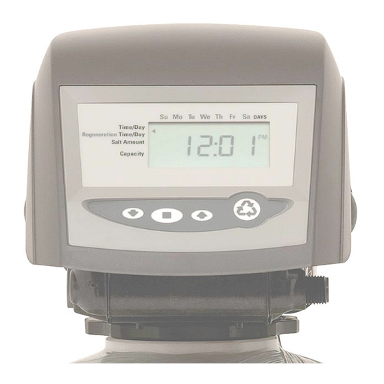
- Page 11 Logix Control Valve Timer Settings: (See Figure 5) Note: The control valve is set at the factory. You only need to set the hardness, time of day and regeneration time if required, which is preset at 2 am. Figure 5 Time of Day Setting 1) Press the SET button.
- Page 12 2) To change the number, use the UP or DOWN arrows. Press the SET button. If water was tested by Master Water Conditioning, follow recommendations on water analysis, for hardness setting. NOTE: If water was not tested by Master Water, multiply the hardness in (gpg) reading you have by two ( 2 ).
- Page 13 Troubleshooting Symptom: Water conditioner fails to regenerate. No soft water. Possible Cause Solution Power supply to 762 control has Determine reason for power been interrupted. interruption and correct. Reset time of day. Water pressure lost. Restore water pressure. For 762 series turbine failure. Clean or replace turbine.
- Page 14 Symptom: Insufficient brine draw Possible Cause Solution Partially clogged injector or injector Inspect and clean injector and/or screen. injector screen assembly. Restricted flow rate in brine line. Check flow rate capabilities of the safety float/aircheck assembly. Insufficient water pressure. Increase water pressure above 25 psig (172kPa) minimum.
- Page 15 Symptom: Leak to Drain Possible Cause Solution No flow control installed in drain Install drain line flow control. line. Insufficient water pressure. Increase water pressure above 25 psig (172kPa) minimum. Damaged valve disk or obstruction InMPect and if damaged, replace all in valve disk.
- Page 20 All claims must be submitted in writing to Master Water Conditioning Corporation at 224 Shoemaker Road, Pottstown, Pennsylvania 19464 within thirty (30) days from the discovery of the defect.
Need help?
Do you have a question about the MP-NS-30T and is the answer not in the manual?
Questions and answers