
Related Manuals for Master Water Conditioning MBA Series


Summary of Contents for Master Water Conditioning MBA Series
- Page 1 MASTER Water Conditioning Corp. www.masterwater.com Installation and Operation Manual MBA Crawl Space Filters with the 255/742 Logix Control Valve July 2015...
- Page 2 Installation and Operating Instructions for 253/742 Logix Top Mount Crawl Space Filters Model #: _______ MBA-AC-10CS Carbon Filter _______ MBA-AN-10CS Acid Neutralizer _______ MBA-FE-10CS Iron Filter _______ MBA-S-10CS Turbidity Filter _______ MBA-AC-1040 Carbon Filter _______ MBA-AN-1040 Acid Neutralizer _______ MBA-FE-1040 Iron Filter _______ MBA-AN-1229 Acid Neutralizer...
- Page 3 ALL UNITS NOW COME WITH THE NEW VORTECH * NO GRAVEL IS NEEDED NOTE: Product Change for MBA-AN-1229 ACID NEUTRALIZER The brine plug (1030334) was added, and the brine sight glass connection is plugged with a red cap (TV-6A Red Cap). See Figure below.
- Page 4 Filter Positioning: 1. Place Filter in desired position, far enough from walls and other obstructions to allow for servicing the unit. 2. Place the Filter within reasonable access to a grounded 115V/60 HZ circuit and a legal drain line connection. Filter Tank Loading: 1.
- Page 5 or PVC tail piece with a nut. Repeat the procedure for the outlet connection. DO NOT OVERTIGHTEN THE NUT. Figure 2 2. The control valve's drain connection is 1/2" npt and is located on the back of the bypass valve. 3.
- Page 6 Figure 3 • The control valve drain connection is 1/2" npt. • Never decrease the drain piping size to below 1/2” • Maximum drain line length is 20 feet. • Maximum drain line height is 6 feet above the control valve. •...
- Page 7 224 Shoemaker Rd. Pottstown, PA 19464 Typical Piping Layout Treated water Air Gap Drain Untreated to outside Master Water Conditioner Well Tank Untreated water from well NOTE: All Master Water Conditioners must be installed after the well tank or water meter if its public water supply.
- Page 8 3. Make sure the electrical service provides power 24 hours per day. We recommend installing a surge protector to protect unit from power surges, which are not covered by warranty. Logix Control Valve Electrical Connection: Note: Do not touch the wiring harness between the Logix timer and the motor, it’s positioning is critical and therefore already installed at the factory.
- Page 9 to cycle C1 (BACKWASH). The controller will indicate the total regeneration time remaining. Filling tank in this position allows air to escape from drain. Open the bypass inlet valve ¼ turn and allow water to flow into the mineral tank at a slow rate. Warning: IF WATER ENTERS THE TANK TOO FAST, ALL THE MEDIA WILL BE FLUSHED TO DRAIN DURING START UP.
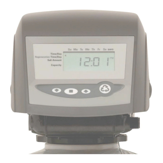
- Page 10 Time of Day Setting 1) Press the SET button. The screen will show the Time of Day in blinking numbers. 2) To change the Time of Day, use the UP or DOWN arrows. 3) Press the SET button. Day of Week Setting 1) Press the SET button.
-
Page 11: Troubleshooting
connection meets all plumbing codes and that the drain line size can handle the backwash flow rate of the filter. 2. Make sure the Inlet and Outlet on bypass valve are open. 3. Make sure the control valve timer is plugged into an electrical outlet with power 24 hours per day. - Page 12 Symptom: Water conditioner fails to regenerate. Dirty water. Possible Cause Solution Power supply to 742 control has Determine reason for power been interrupted. interruption and correct. Reset time of day. Water pressure lost. Restore water pressure. Corrupted programming of 742 Reprogram timer assembly.
- Page 17 Table of Contents Page Topic Description Model # and Packaging Packaging Information Component Packaging Description Packaging Description Filter System System Positioning Filter Tank Loading Filling with Media Logix 253/742 Control Valve Attaching Valve to Tank Logix 253/742 Control Valve, cont’d Attaching Valve to Tank, cont’d Service &...
Need help?
Do you have a question about the MBA Series and is the answer not in the manual?
Questions and answers