
Related Manuals for Mimosa G3232


Summary of Contents for Mimosa G3232
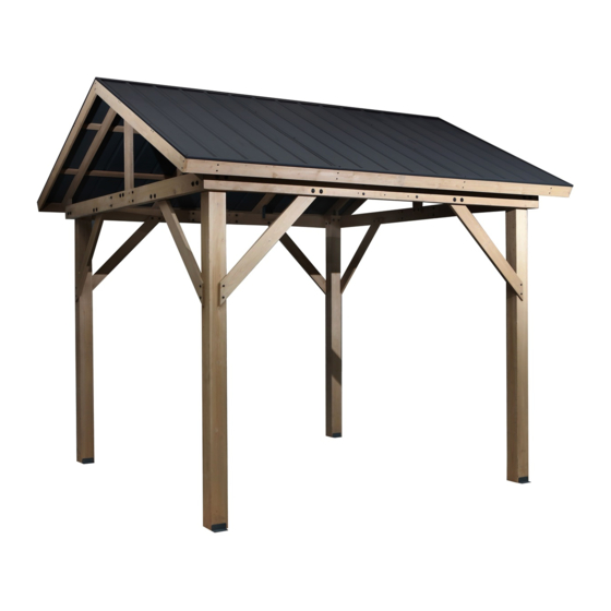
- Page 1 ASSEMBLY INSTRUCTIONS OUTDOOR WOODEN GAZEBO 100% FSC Certified Cedar Galvanised Steel Roof 3.2L x 3.2W x 3.0H metres Laminated Cedar Timber Frame - Natural Oil Finish 3.2M HEIGHT: 3.0M...
- Page 2 Warning The ground for erecting and anchoring gazebo is required to be a level, solid and safe surface. Beware existing utilities surface. Keep away from any electrical installations and transportation devices. Keep away flame or heat source (ex. fire pit, grills, etc.) from wood parts otherwise wood could burn and be damaged.
- Page 3 TIMBER CARE & MAINTENANCE REQUIREMENTS PLEASE READ AS YOUR WARRANTY MAYBE VOID IF YOU DON’T FOLLOW CARE INSTRUCTIONS ASSEMBLY Easy to follow instructions are provided for the assembly of your gazebo. As an added precaution we strongly recommend you tighten any loose components after an initial period of use (around 3-6 months).
- Page 4 Assembly Tools Required (Not Supplied): 8’ Ladder x 1 / 6’ Ladder x2 / Tape Measure / L-Square Rule / Carpenters Water Level Rule / Drill / Hammer /Screwdriver or Power Screwdriver / Safety Glasses / Hard Hat / Safety Gloves Below symbols are placed at the top of each page as a guide for what may be required.
- Page 5 Hardware Kit: Bolt M10X180MM Bolt M8X60MM Bolt M8X80MM Wood Bolt M5X25MM Wood Bolt M5X38MM Wood Bolt M5X50MM Self tapping screw M5X30MM Self tapping screw M8X40MM Washer Washer Washer Spanner Cross wrench...
- Page 6 Roof frame & roof panels overview. Roof rafter Roof panel Roof rafter Roof panel Side rafter Roof panel cap Roof panel cap Roof rafter Roof rafter Roof cap Roof support rafter Roof cap Roof panel profile Connecting rafter Connecting rafter Roof panel profile Supporting rafter U shape bracket...
- Page 7 Rafters overview Post Crossbar for side (Right) Crossbar for side (Left) Crossbar for side (Left) Crossbar for side (Right) Roof rafter Corner supporter (Right) Corner supporter (Left) Base flange Stake...
- Page 8 Assembly of base frame (P7~P13) x 16 Step 1: Attach the base flange to the 4 posts.
- Page 9 x 24 Step 2: Join together the two cross bar sets - B1 & B2.
- Page 10 x 16 Step 3: Join together the two cross bar sets - C1 & C2.
- Page 11 B1/B2 Step 4: Join the cross bar sets (B1 & B2) to leg posts A.
- Page 12 C1/C2 347.9cm Post to Post 282cm Step 5: Now add the cross bar sets (C1 & C2) to leg posts A.
- Page 13 x 16 x 16 x 32 x 16 Step 6: Now add the corner supports (E1 & E2) to the posts (A) and cross beams (B & C).
- Page 14 Step 7: Attach the vertical brace (D) to cross beams C1 & C2.
- Page 15 Roof frame panel overview. Part 2 Part 1 Part 2 Part 1 Part 3 Part 2 Part 1 Part 2 Part 3...
- Page 16 Assembly of roof frame panel (P15~P18) x 48 X 2PCS 250mm 250mm X 4PCS 250mm 250mm Step 1: Connect the side rafters (G) together using connecting rafter (K). Then repeat and join roof support rafter (J) together using connecting rafter (K).
- Page 17 x 16 x 2PCS 250mm 250mm F1/F2 K F1/F2 Step 2: Connect the roof rafters (F1 & F2) together using connecting rafter (K).
- Page 18 x 48 x 2PCS F1/F2 Step 3: Connect roof rafters (H & I) to the assembled roof frame (as pictured).
- Page 19 x 48 x 2PCS Step 4: Connect roof support rafter (J) to the assembled roof frame (as pictured). Ensure your roof frame is square before proceeding.
- Page 20 Assembly of the left roof panels (P21~P23)
- Page 21 Fig.1 10mm Fig.3 Panel alignment edges panels overlap at the seams 20mm 10mm Fig.4 Fig.2 Step 1: Place Roof Panel (P1) in the left edge of the assembled roof rafter, kindly be advised that the hole center in the left side of Roof Panel (P1) should align the center of Roof rafter (H) (Fig.1).
- Page 22 Tips: Fix Self tapping screw in the middle and top of roof panels first, then fix the bottom hole with Roof panel profile (S1 / S2) finally. x 12 x 12 Fig. 2 Fig. 1 Fig. 3 Step 2: Connect Roof panel cap (Q1) and Roof panel (P1) together using Self tapping screw (GG) and Washer (II), connect Roof panel cap (Q2) and Roof panel (P2) together using Self tapping screw (GG) and Washer (II) (Fig.1).
- Page 23 Tips: Fix Self tapping screw in the middle and top of roof panels first, then fix the bottom hole with Roof panel profile (S1 / S2) finally. Fig. 4 Fig. 4 Fig. 4 Step 3: Connect Roof panel profile (S1/S2) and Roof panel (P1/P2) together using Self tapping screw (GG) and Washer (II) (Fig.4).
- Page 24 Step 4: Confirm Roof panel (P1 / P2) and Roof panel cap (Q1 / Q2) and Roof panel profile (S1 / S2) after all are connected together, fix Roof panel (P1/P2) onto Roof support rafter (J) using Self tapping screw (GG) and Washer (II).
- Page 25 Assembly of right roof panels (P25~P29)
- Page 26 Fig. 4 20mm 10mm Fig. 3 Fig. 1 panels overlap 10mm at the seams Panel alignment edges Fig. 2 Step 1: Place Roof panel(P1)in the left edge of the assembled roof rafter, kindly be advised that the hole center in the left side of Roof Panel (P1) should align the center of Roof rafter (H)(Fig.1). Place Roof panel (P2) in the middle of the roof rafter, left edge of Roof panel (P2) should press against the right edge of Roof Panel (P1).
- Page 27 Tips: Fix Self tapping screw in the middle and top of roof panels first, then fix the bottom hole with Roof panel profile (S1/S2) finally. Step 2: Connect Roof panel cap (Q1) and Roof panel (P1) together using Self tapping screw (GG) and Washer (II), connect Roof panel cap (Q2) and Roof panel (P2) together using Self tapping screw (GG) and Washer (II).
- Page 28 Tips: Fix Self tapping screw in the middle and top of roof panels first, then fix the bottom hole with Roof panel profile (S1/S2) finally. Fig. 2 II S1 Fig. 1 Step 3: First insert the Roof panel profile (S1 & S2) into each other (Fig.1), connect Roof panel profile (S1 / S2) and Roof panel (P1 / P2) together using Self tapping screw...
- Page 29 Tips: Fix Self tapping screw in the middle and top of roof panels first, then fix the bottom hole with Roof panel profile (S1/S2) finally. Step 4: Connect Roof cap (R1 / R2) and Roof panel (P1 / P2) together using Self tapping screw (GG) and Washer (II), then connect Roof cap (R1 / R2) and Roof panel cap(Q1 / Q2) together using Self tapping screw (GG) and Washer (II).
- Page 30 Step 5: Confirm Roof panel (P1 /P2) and Roof panel cap (Q1 / Q2) and Roof panel profile (S1 / S2) together Roof cap(R1 / R2) , then fix Roof panel (P1 / P2) onto Roof support rafter (J) using Self tapping screw (GG) and Washer (II).
- Page 31 Securing the underside of the roof panels to the roof frames (P30~P31) x 16 Fig.2 Fig.1 Fig.2 Step 1: Flip the assembled roof rafter with roof panles over. Connect the Connecting rafter (L) with L shape bracket (N) using Wood Bolt (DD) at the bottom of both sides of Roof rafter (I).
- Page 32 x 16 Step 2: Flip the assembled roof rafter with roof panles over. Connect the Connecting rafter (L) with L shape bracket (N) using Wood Bolt (DD) at the bottom of both sides of Roof rafter (I). * Tips: Distance between Connecting rafter (L) and the Fig.1 bottom is 135MM as shown in ( Fig.1).
- Page 33 Installing the roof panels to the frame (P32~P38) Step 1: Using 4 people and ladders, carefully lift the completed roof panel on to the frame.
- Page 34 Step 2: Connect the roof panel to the frame using brackets (N) and screw (DD).
- Page 35 Step 3: Using 4 people and ladders, carefully lift the completed roof panel on to the frame.
- Page 36 F1 F2 Step 4: Secure the roof panels to the frame using screws (FF) and (DD) as pictured.
- Page 37 x 16 F1/F2 Step 5: Use the V shaped bracket (V) to secure the underside of the roof frame supports (I).
- Page 38 x 16 F1/F2 Step 5: Use the V shaped bracket (V) to secure the underside of the roof frame supports (I).
- Page 39 x 24 Supporting rafter alignment edges Step 6: Add the supporting rafters (M) to the roof frame using brackets (U) and screws (DD).
- Page 40 Step 7: Secure the roof sheets and ridge to the roof frame, using screws (GG) and washer (II).
- Page 41 347.9cm Post to Post 282cm Step 8: Securing pegs can be used to secure your gazebo to the ground if positioned on grass or soil. If mounting on concrete, masonary anchors will need to be used (not provided).
-
Page 42: Warranty Conditions
WARRANTY CONDITIONS Any claim under this warranty must be made within 3 years of the date of purchase of the product. To make a claim under the warranty, take the product (with proof of purchase) to any Bunnings store (see www.bunnings.com.au or www.bunnings.co.nz for store locations). Bunnings Group Ltd bears reasonable, direct, expenses of claiming under the warranty.
Need help?
Do you have a question about the G3232 and is the answer not in the manual?
Questions and answers