Table of Contents

Related Manuals for Sullivan-Palatek 75UDG


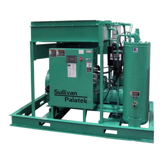
Summary of Contents for Sullivan-Palatek 75UDG
- Page 1 OPERATING AND PARTS MANUAL INDUSTRIAL ELECTRIC AIR COMPRESSORS 75UDG AND 100UDG MODELS WITH T1 MICRO PROCESSOR CONTROL PALATEK, INC. dba SULLIVAN-PALATEK MICHIGAN CITY, IN 46360 ALL RIGHTS RESERVED COPYRIGHT 2011 10-26-2011 Part Number: OPM75100T1...
-
Page 3: Table Of Contents
_____________________________________SULLIVAN-PALATEK TABLE OF CONTENTS SECTION 1 - SAFETY ..................4 1.1 GENERAL ......................4 1.2 PRESSURE RELEASE ..................4 1.3 FIRES/EXPLOSIONS ..................5 1.4 MOVING PARTS ....................5 1.5 PHYSICAL DANGERS ..................6 1.6 TOXICITY ......................6 1.7 ELECTRIC SHOCK ....................6 1.8 ... - Page 4 SULLIVAN-PALATEK_____________________________________ SECTION 6 - MAINTENANCE ................22 6.1 MAINTENANCE SCHEDULE ................22 6.2 OIL FILTER ......................23 6.3 AIR FILTER ......................23 6.4 AIR/OIL SEPARATOR ..................23 6.5 PRESSURE ADJUSTMENT ................24 6.6 SERVICE/MAINTENANCE PROCEDURES ............24 6.7 TROUBLESHOOTING ..................25 SCREW COMPRESSOR AIR-END EXCHANGE PROGRAM ......
-
Page 5: Section 1 - Safety
SECTION 1 - SAFETY GENERAL SULLIVAN-PALATEK designs all its compressors so they can be operated safely despite the fact that operating a motor driven air compressor is inherently hazardous. Responsibility for continued safe operation rests with those who install, use and maintain the equipment. -
Page 6: Fires/Explosions
SULLIVAN-PALATEK_____________________________________ Do not use air pressure greater than 30 PSI (207 kPa) for blow-off or cleaning purposes, and then only with effective chip guarding and personal protective equipment as required by OSHA. Compressed air filters or lubricators with plastic bowls may be affected by lubricant and should not be used. -
Page 7: Physical Dangers
_____________________________________SULLIVAN-PALATEK PHYSICAL DANGERS Wear OSHA approved personal protective gear including gloves, safety shoes, safety glasses, head covering, and ear protection when working on or around the compressor. Avoid bodily contact with hot oil, hot surfaces, sharp edges and corners. Keep all parts of the body away from all potential points of air discharge, including pressure relief valve ports. -
Page 8: Lifting
SULLIVAN-PALATEK_____________________________________ LIFTING Lift or move the compressor only with equipment of sufficient load capacity that has been inspected and is in good condition. Keep personnel out from under and away from the area when lifting or moving the compressor. Lift no higher than necessary. Carry as low as possible when moving. Keep lifting operator in attendance whenever compressor is suspended. -
Page 9: Hazard Warning Signs
_____________________________________SULLIVAN-PALATEK 1.11 HAZARD WARNING SIGNS SULLIVAN-PALATEK compressors are all equipped with brightly colored, weather- resistant, pictorial/verbal self-adhesive decals. These are designed to warn the operator against potential hazards in order to minimize risk of property damage, bodily injury or death. All operators must be aware of the Warning Signs and follow the instructions thereon. -
Page 10: Section 2 - Specifications
NOTE: SEE INSTALLATION DRAWINGS ON PAGES 55-58 OF THIS MANUAL DATA AND DIMENSIONS SULLIVAN-PALATEK reserves the right to change the design or construction of the above compressors, or to offer them with options which will cause subject equipment to differ from the above specifications, without reference to any descriptions in this manual. -
Page 11: Application Guide
For instrument-grade air, contact the factory for recommendations related to specialized compressed air preparation accessories. Whenever a SULLIVAN-PALATEK rotary screw compressor is installed in parallel with a reciprocating type of compressor, it is imperative that the SULLIVAN-PALATEK be the “lead”... -
Page 12: Intake/Control System
SULLIVAN-PALATEK_____________________________________ INTAKE/CONTROL SYSTEM The intake/control system consists of: an air filter, connecting rubber elbow, a combination compressor inlet valve/reverse-flow check valve, control signal regulator valve, blowdown valve, and control pressure transducer. (See Intake Control Schematic.) The air filter is a multi-stage dry-type with a high efficiency cleanable/replaceable cellulose element. -
Page 13: Compressor Lubrication/Cooling System
_____________________________________SULLIVAN-PALATEK Note that the micro processor is programmed to limit the number of starts per hour (depending on motor size) for motor protection. If the compressor is starting too often, thus causing the compressor to be off when air is required; please contact the factory for adjustments to be made to the controls to avoid this problem (i.e. -
Page 14: Compressor Discharge System
SULLIVAN-PALATEK_____________________________________ Pressure in the oil separation tank utilizes air pressure over oil which causes the lubricoolant to flow from this region of relatively high pressure through the system to an area of lower pressure at the compressor unit. Fluid flows from the oil separation tank to the cooler;... - Page 15 _____________________________________SULLIVAN-PALATEK lock out the electrical disconnect switch, and relieve all sump pressure before doing so. The oil separation tank is ASME rated for 200 psig (1380 kPa) maximum working pressure. A combination minimum-pressure/check valve in the separator cover assures a minimum pressure of 60 psig (415 kPa) for proper lubricoolant circulation and separation.
-
Page 16: Starter And Electrical Parts
SULLIVAN-PALATEK_____________________________________ STARTER AND ELECTRICAL PARTS The three-phase electric motor starter supplied with the SULLIVAN-PALATEK Plant Air Compressor has a NEMA-1 rated enclosure. This is also the location of: the control power transformer, the control pressure transducer, the sump pressure sensor, fan motor disconnect fuses, and fan overload. -
Page 17: Section 4 - Installation
It is possible to utilize this heat for space heating, combustion air pre-heating, product drying, etc., --providing that no additional restriction is imposed upon the compressor cooling fan. Consult the factory for assistance if heat recovery is desired. Model 75UDG 100UDG AIRFLOW (CFM) 7,500 9,500... -
Page 18: Wiring Diagram, Full Voltage Starter (Standard)
SULLIVAN-PALATEK_____________________________________ 4.5a WIRING DIAGRAM, FULL VOLTAGE STARTER (STANDARD) DISC101 FUSIBLE DISCONNECT SWITCH BY CUSTOMER POWER COMPRESSOR SUPPLY MOTOR 3 Phase 60 Hz FU105 MOTOR CB109 Fuse size determined by horsepower [H2] [H3] T110 TRANSFORMER CB111 208,230,460/120 VAC [X1] [X2] [H1] [H2] T1 Microprocessor T112... -
Page 19: Wiring Diagram Y - Delta Start (Optional)
_____________________________________SULLIVAN-PALATEK 4.5b WIRING DIAGRAM Y - DELTA START (OPTIONAL) DISC101 FUSIBLE DISCONNECT SW ITCH BY CUSTOMER POWER SUPPLY [T6] [T1] 3Ø 60 Hz COMPRESSOR [T4] [T3] MOTOR [T5] [T2] FOR PROPER MOTOR WIRING, SEE MOTOR WIRING INFORMATION FU107 COOLING FAN MOTOR Fuse size and circuit components determined by HP CB109... -
Page 20: Direction Of Rotation
SULLIVAN-PALATEK_____________________________________ DIRECTION OF ROTATION Once the control circuit has been checked, all piping installed, and compressor is filled with lubricoolant, push the ‘run’ key (green) followed by the ‘stop’ button (red) and observe the direction of rotation. If rotation direction is incorrect, there may be a fault signal appear (ER0050). -
Page 21: Section 5 - Operation
_____________________________________SULLIVAN-PALATEK SECTION 5 - OPERATION INTRODUCTION Read this entire Operator’s Manual to familiarize yourself with the SULLIVAN-PALATEK Plant Air Compressor, giving special attention to the Section 1 - SAFETY. INITIAL START Open main disconnect to be sure there is no power to the compressor. -
Page 22: Normal Operation
SULLIVAN-PALATEK_____________________________________ d. When the appropriate access code is shown, press ‘enter’. e. After the access code has been selected, use the ‘up’ (+) or ‘down’ (-) key to select the corresponding parameter menu (i.e. PO1, PO2, or PO4) Once the parameter has been selected, use the ‘up’ (+) or ‘down’ (-) key to select the setting to be changed g. -
Page 23: Section 6 - Maintenance
_____________________________________SULLIVAN-PALATEK SECTION 6 - MAINTENANCE MAINTENANCE SCHEDULE Daily -1. Check lubricoolant level prior to start-up 2. Drain condensate from auxiliary tank. 3. Check micro processor for any fault or alarm codes (see 5.2 instructions.) 4. Keeping a daily log of all operating parameters is recommended. First 50 hours - Change compressor lubricoolant filter element. -
Page 24: Oil Filter
SULLIVAN-PALATEK_____________________________________ OIL FILTER (Replace if differential pressure exceeds 15psid fault, H6 signal is shown, or every 1000 hrs.) 1. Open and lock-out main disconnect. 2. Relieve all internal system pressure. 3. Using a strap wrench, remove spin-on oil filter elements. 4. -
Page 25: Pressure Adjustment
_____________________________________SULLIVAN-PALATEK PRESSURE ADJUSTMENT Note: prior to making any control pressure adjustments, turn the adjusting screw on the modulating (or regulating) valve in several turns to get it out of the action. Once the control has been set, then the regulating (or modulating) valve is re-adjusted so that it starts operating (as determined by air coming out the vent hole in cap) at 5 PSIG lower pressure than the control set pressure. -
Page 26: Troubleshooting
SULLIVAN-PALATEK_____________________________________ Use the ‘up’ (+) or ‘down’ (-) key to pick other settings to be changed. J. Once the desired settings have been changed, press the ‘C’ twice (or hold the ‘reset’ for 2 seconds) to return to the main menu TROUBLESHOOTING SYMPTOM PROBABLE CAUSES AND REMEDIES... - Page 27 _____________________________________SULLIVAN-PALATEK d. Clogged oil filter. Change the oil filter element. e. Thermostat not working properly. Replace. Check for proper cooling fan operation. Fan should always be running between 165° to 190°F. SYMPTOM PROBABLE CAUSES AND REMEDIES C. MACHINE WILL NOT BUILD UP FULL 1.
- Page 28 SULLIVAN-PALATEK_____________________________________ 5. Operating pressure below 60 psig. Repair minimum pressure valve. SYMPTOM PROBABLE CAUSES AND REMEDIES F. RELIEF VALVE OPENS REPEATEDLY 1. Faulty Pressure Relief Valve. Replace. 2. Incorrect control settings. Re-adjust/as per SYMPTOM PROBABLE CAUSES AND REMEDIES G. LINE PRESSURE VENTING THROUGH 1.
- Page 29 _____________________________________SULLIVAN-PALATEK PARTS LISTING...
-
Page 30: Screw Compressor Air-End Exchange Program
An exchange air-end has a warranty that is 12 months from startup date or 18 months from date of shipment in accordance with the terms set forth in the SULLIVAN-PALATEK Warranty policy on pages 52 & 53. -
Page 31: Section 7 - Parts List
SECTION 7 - PARTS LIST PARTS ORDERING Parts should be ordered from the nearest full-service Distributor or Factory Authorized Compressor Center. If parts cannot be obtained locally, contact the factory directly. SULLIVAN-PALATEK 1201 W. HWY. 20 MICHIGAN CITY, IN 46360 TELEPHONE: 219-874-2497 FAX: 219-872-5043 E-mail: info@palatek.com... - Page 32 SULLIVAN-PALATEK_____________________________________ MOTOR, COMPRESSOR AND MOUNTING PARTS...
-
Page 33: Motor Compressor And Mounting Parts
_____________________________________SULLIVAN-PALATEK MOTOR COMPRESSOR AND MOUNTING PARTS 75HP MOTOR 100HP MOTOR #08741-075 #08741-100 TEFC #08747-075 TEFC #08747-100... - Page 34 SULLIVAN-PALATEK_____________________________________ LUBRICATION AND COOLING SYSTEM - AIR COOLED...
-
Page 35: Lubrication And Cooling System - Air Cooled
_____________________________________SULLIVAN-PALATEK LUBRICATION AND COOLING SYSTEM - AIR COOLED ** GASKET SUPPLIED WITH OIL FILTER AND CAN’T BE ORDERED SEPERATELY. Water Cooled Machines: 75 hp 100 hp Oil Cooler #00549-005 Oil Cooler #00549-008 After Cooler #00549-004 After Cooler #00549-005 Water Reg. Valve #18338-020 Water Reg. - Page 36 SULLIVAN-PALATEK_____________________________________ INTAKE AND CAPACITY CONTROL SYSTEM...
-
Page 37: Intake And Capacity Control System - 75G & 100G
_____________________________________SULLIVAN-PALATEK INTAKE AND CAPACITY CONTROL SYSTEM - 75G & 100G... - Page 38 SULLIVAN-PALATEK_____________________________________ DISCHARGE SYSTEM 75 &100G...
-
Page 39: Discharge System - 75 & 100G
_____________________________________SULLIVAN-PALATEK DISCHARGE SYSTEM - 75 & 100G... - Page 40 SULLIVAN-PALATEK_____________________________________ MICROPROCESSOR CONTROL & ELECTRICAL PARTS - OPEN...
-
Page 41: Microprocessor Control & Electrical Parts - Open
_____________________________________SULLIVAN-PALATEK MICROPROCESSOR CONTROL & ELECTRICAL PARTS - OPEN... - Page 42 SULLIVAN-PALATEK_____________________________________ MICROPROCESSOR CONTROL - ENCLOSED...
-
Page 43: Microprocessor Control - Enclosed
_____________________________________SULLIVAN-PALATEK MICROPROCESSOR CONTROL - ENCLOSED... - Page 44 SULLIVAN-PALATEK_____________________________________ ENCLOSURE - AIR COOLED UD...
-
Page 45: Enclosure - Air Cooled Ud
_____________________________________SULLIVAN-PALATEK 7.10 ENCLOSURE - AIR COOLED UD... - Page 46 SULLIVAN-PALATEK_____________________________________ ENCLOSURE - WATER COOLED UD...
-
Page 47: Enclosure - Water Cooled Ud
_____________________________________SULLIVAN-PALATEK 7.11 ENCLOSURE - WATER COOLED UD WATER COOLED VENT FAN P.N. 18080-016 1 QUANTITY NOT SHOWN IN DRAWING. -
Page 48: 7.13A Decal And Identification
SULLIVAN-PALATEK_____________________________________ 7.13a DECAL AND IDENTIFICATION ITEM DESCRIPTION MODEL 75UDG MODEL 100UDG PLATE, NAME/S.N. 03832-043 03832-043 DECAL, VOLTAGE 460 08377-001 08377-001 DECAL, WARNING 08377-043 08377-043 DECAL, WARNING 08377-045 08377-045 DECAL, WARNING 08377-046 08377-046 DECAL, 3-POSITION SWITCH 08378-048 08378-048 DECAL, INSTRUCTIONS 08379-011... -
Page 49: 7.13B Decal And Identification
_____________________________________SULLIVAN-PALATEK 7.13b DECAL AND IDENTIFICATION T1 INSTRUCTIONS USER INTERFACE P01 USER SETTINGS Do not change P01 USER SETTINGS without Keypad consulting the factory as this may void the warranty. BUTTON NAME FUNCTION P02 FAULT LOG START Enter STARTED condition. Reading the Fault History Enter the access code 0009. -
Page 50: Section 8 - Warranty
Sullivan-Palatek; whichever is the first to occur. Compressor unit (excluding shaft seal) and Coupling Assembly (excluding elements): 24 months from the date of start-up by an authorized distributor or 30 months from date of shipment by Sullivan-Palatek; whichever is the first to occur. - Page 51 Platinum Warranty and that warranty is herein incorporated by reference. Component Coverage: Platinum Warranty: Parts and labor to repair or replace as deemed necessary solely by Sullivan-Palatek, Inc. the Compressor Air End, Compressor Motor, VFD Drive, Fan Motor (if installed) Air and Oil Coolers, Sump Tank, and Drive Coupling Assembly (excluding elements).
-
Page 52: Section 9 - General Arrangement Drawings
SULLIVAN-PALATEK_____________________________________ SECTION 9 - GENERAL ARRANGEMENT DRAWINGS P&I DIAGRAM – AIR COOLED... -
Page 53: General Arrangement - 75-100Hp Udac, Open
_____________________________________SULLIVAN-PALATEK GENERAL ARRANGEMENT - 75-100HP UDAC, OPEN... -
Page 54: General Arrangement - 75-100Hp Udac, Enclosed
SULLIVAN-PALATEK_____________________________________ GENERAL ARRANGEMENT - 75-100HP UDAC, ENCLOSED... -
Page 55: General Arrangement - 75-100Hp Wc, Open
_____________________________________SULLIVAN-PALATEK GENERAL ARRANGEMENT - 75-100HP WC, OPEN... -
Page 56: General Arrangement - 75-100Hp Wc, Enclosed
SULLIVAN-PALATEK_____________________________________ GENERAL ARRANGEMENT - 75-100HP WC, ENCLOSED... -
Page 57: Sullivan - Palatek Compressor Maintenance Log
_____________________________________SULLIVAN-PALATEK SULLIVAN - PALATEK COMPRESSOR MAINTENANCE LOG S/N: SERVICE DIST: FILL OUT FOR EACH SERVICE OR REPAIR. MORE THAN ONE LINE MAY BE USED PER EACH SERVICE OR REPAIR. THIS FORM MAY BE PHOTOCOPIED AS NEEDED. SERVICE CHANGE CHANGED PART DATE HOURS NUMBER...
Need help?
Do you have a question about the 75UDG and is the answer not in the manual?
Questions and answers