Table of Contents
Advertisement
Advertisement
Table of Contents

Related Manuals for MSI 945PL Neo Series


Summary of Contents for MSI 945PL Neo Series
- Page 1 945PL Neo Series MS-7236 v2.X Mainboard G52-72361X5...
-
Page 2: Copyright Notice
If a problem arises with your system and no solution can be obtained from the user’s manual, please contact your place of purchase or local distributor. Alternatively, please try the following help resources for further guidance. Visit the MSI website for FAQ, technical guide, BIOS updates, driver updates, and other information: faq/esc_faq_list.php Contact our technical staff at: http://support.msi.com.tw... -
Page 3: Safety Instructions
Safety Instructions Always read the safety instructions carefully. Keep this User’s Manual for future reference. Keep this equipment away from humidity. Lay this equipment on a reliable flat surface before setting it up. The openings on the enclosure are for air convection hence protects the equip- ment from overheating. -
Page 4: Fcc-B Radio Frequency Interference Statement
FCC-B Radio Frequency Interference Statement T hi s equipment has b een tested and found to comply with the limits for a Class B digital device, pursuant to Part 15 of the FCC Rules. These limits are designed to provide reasonable protection against harmful interference in a residential installation. -
Page 5: Weee (Waste Electrical And Electronic Equipment) Statement
WEEE (Waste Electrical and Electronic Equipment) Statement... -
Page 8: Table Of Contents
Copyright Notice ... ii Trademarks ... ii Revision History ... ii Technical Support ... ii Safety Instructions ... iii FCC-B Radio Frequency Interference Statement ... iv WEEE Statement ... v Chapter 1. Getting Started ... 1-1 Mainboard Specifications ... 1-2 Mainboard Layout ... - Page 9 Front Panel Connectors: JFP1 / JFP2 ... 2-17 Front USB Connectors: JUSB1 / JUSB2 ... 2-18 Front Panel Audio Connector: JAUD1 ... 2-18 IrDA Infrared Module Header: JIR1 ... 2-19 Serial Port Connector: JCOM1 ... 2-19 Chassis Intrusion Switch Connector: JCI1 ... 2-19 SPDIF-Out Connector: JSPD1 ...
-
Page 10: Chapter 1. Getting Started
Chapter 1 Getting Started Thank you for choosing the 945PL Neo (MS-7236 v2.X) ATX mainboard. The 945PL Neo mainboard is based on Intel 945PL and Intel ® optimal system efficiency. Designed to fit the ad- vanced Intel Pentium 4 LGA775 processor, the ®... -
Page 11: Mainboard Specifications
- Supports 2004 Perform ance EMB CPU VR Design - Supports 3/4 pin CPU Fan Pin-Header with Fan Speed Control - Supports Intel Hyper-Threading Technology (For the latest information about CPU, please visit http://www.msi. com.tw/program/products/mainboard/mbd/pro_mbd_cpu_support.php) Supported FSB - 533 / 800 MHz... -
Page 12: Getting Started
Getting Started Connectors Back panel - 1 PS/2 m ouse port - 1 PS/2 keyboard port - 1 serial port - 1 parallel port supports SPP/EPP/ECP m ode - 4 USB 2.0 Ports - 1 RJ-45 LAN jack - 6 flexible audio jacks (Line-In / Line-Out / MIC-In / Rear Speaker-Out / Center-Subwoofer Speaker-Out/ Surround-Out) On-Board Pinheaders - 2 USB 2.0 pinheaders... -
Page 13: Mainboard Layout
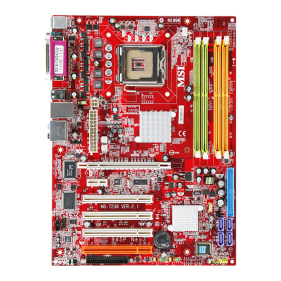
T:R S- Out SYSFAN1 M:CS- Out B:SS- Out PCI_E1 RTL8110SC PCI_E2 JIR1 JCI1 PCI1 Winbond W83627DHG PCI2 PCI3 JCOM1 ALC850 PCI4 JAUD1 (MS-7236 v2.X) ATX Mainboard CPUFAN1 Intel 945PL Intel ICH7 BATT JUSB2 JUSB1 FDD1 945PL Neo Series JFP1 JFP2... -
Page 14: Packing Checklist
Getting Started Packing Checklist SATA Cable x 1 MSI mainboard MSI Driver/Utility CD (Optional) Standard Cable for Power Cable User’s Guide IDE Devices (Optional) Back IO Shield * These pictures are for your reference only. Your packing contents may vary de-... -
Page 15: Core Center
M S-7236 M ainboard Core Center Click on the Core Center icon in the main menu and the Core Center program will be enabled. CoreCenter is just like your PC doctor that can detect, view and adjust the PC hardware and system status during real time operation. In the left side it shows the current system status including the Vcore, 3.3V, +5V and 12V. -
Page 16: Left-Wing: Current System Status
Getting Started Left-wing: Current system status In the left sub-menu, you can configure the settings of FSB, Vcore, Memory Voltage and AGP Voltage by clicking the radio button next to each item and make it available (the radio button will be lighted as yellow when selected), use the “+” and “-”... -
Page 17: Chapter 2. Hardware Setup
Chapter 2 Hardware Setup This chapter provides you with the information about hard- ware setup procedures. W hile doing the installation, be careful in holding the components and follow the installa- tion procedures. For some components, if you install in the wrong orientation, the components will not work properly. -
Page 18: Quick Components Guide
JIR1, p.2-19 JCI1, p.2-19 JCOM1, p.2-19 CD_IN1, p.2-17 JAUD1, JSPD1, p.2-18 p.2-20 (MS-7236 v2.X) ATX Mainboard p.2-9 CPUFAN1 p.2-3 p.2-14 FDD1, PCI Slots, JUSB1-2, p.2-14 p.2-22 p.2-18 945PL Neo Series DIMM1-2, p.2-7 IDE1, p.2-15 SATA1-4, p.2-16 JBAT1, p.2-21 JFP1-2, p.2-17... -
Page 19: Central Processing Unit: Cpu
CPU socket called LGA775. When you are installing the CPU, make sure to install the cooler to prevent overheating. If you do not have the CPU cooler, contact your dealer to purchase and install them before turning on the computer. (For the latest information about CPU, please visit http://www.msi.com.tw/program/ products/mainboard/mbd/pro_mbd_cpu_support.php) Important... -
Page 20: Cpu & Cooler Installation
M S-7236 M ainboard CPU & Cooler Installation W hen you are installing the CPU, make sure the CPU has a cooler attached on the top to prevent overheating. If you do not have the cooler, contact your dealer to purchase and install them before turning on the computer. Meanwhile, do not forget to apply some silicon heat transfer compound on CPU before installing the heat sink/cooler fan for better heat dispersion. - Page 21 5. Lift the load lever up and open the load plate. 7. Visually ins pect if the CPU is seated well into the socket. If not, take out the CPU with pure vertical motion and reinstall. Important 1. Confirm if your CPU cooler is firmly installed before turning on your system.
- Page 22 M S-7236 M ainboard 9. Press down the load lever lightly onto the load plate, and then se- cure the lever with the hook under retention tab. 11. Press the four hooks down to fas- ten the cooler. Then rotate the lock- ing switch (refer to the correct di- rection marked on it) to lock the hooks.
-
Page 23: Memory
DDR II standard is not backward compatible, you should always install DDR II memory module in the DDR II slot (DIMM1~DIMM2). Otherwise, you are not able to boot up your system and your mainboard might be damaged. (For the updated supporting memory modules, please visit http://www.msi.com.tw/program/products/mainboard/ mbd/pro_mbd_trp_list.php) Memory Module Population Rules Install at least one DIMM module on the slots. -
Page 24: Installing Ddr Ii Modules
M S-7236 M ainboard Installing DDR II Modules 1.The DDR II DIMM has only one notch on the center of module. The module will only fit in the right orientation. 2.Insert the DIMM memory module vertically into the DIMM slot. Then push it in until the golden finger on the memory module is deeply inserted in the socket. -
Page 25: Power Supply
Power Supply The mainboard supports ATX power supply for the power system. Before inserting the power supply connector, always make sure that all components are installed properly to ensure that no damage will be caused. ATX 24-Pin Power Connector: ATX1 This connector allows you to connect an ATX 24-pin power supply. -
Page 26: Back Panel
M S-7236 M ainboard Back Panel The back panel provides the following connectors: M ou se Parallel Keyboard COM Port Mouse/Keyboard Connector The mainboard provides a standard PS/2 attaching a PS/2 mouse/keyboard. You can plug a PS/2 ® into this connector. The connector location and pin assignments are as follows: PS/2 Mouse / Keyboard (6-pin Female) Serial Port Connector: COM Port... -
Page 27: Usb Connectors
USB Connectors The mainboard provides an OHCI (Open Host Controller Interface) Universal Serial Bus root for attaching USB devices such as keyboard, mouse or other USB-compat- ible devices. You can plug the USB device directly into the connector. USB Ports LAN (RJ-45) Jack (1000Mbps is optional) The mainboard provides 1 standard RJ-45 jack for connection to single Local Area Network (LAN). -
Page 28: Audio Port Connectors
M S-7236 M ainboard Audio Port Connectors The left 3 audio jacks are for 2-channel mode for stereo speaker output: Line Out is a connector for Speakers or Headphones. Line In is used for external CD player, Tape player, or other audio devices. Mic is a connector for microphones. However, there is an advanced audio application provided by Realtek ALC850 to offer support for 7.1-channel audio operation and can turn rear audio connectors from 2-channel to 4-/5.1-/7.1- channel audio. -
Page 29: Parallel Port Connector: Lpt1
Parallel Port Connector: LPT1 The mainboard provides a 25-pin female centronic connector as LPT. A parallel port is a standard printer port that supports Enhanced Parallel Port (EPP) and Extended Capabilities Parallel Port (ECP) mode. Pin Definition SIGNAL DESCRIPTION STROBE Strobe DATA0 Data0... -
Page 30: Connectors
M S-7236 M ainboard Connectors The mainboard provides connectors to connect to FDD, IDE HDD, case, LAN, and USB Ports. Floppy Disk Drive Connector: FDD1 The mainboard provides a standard floppy disk drive connector that supports 360K, 720K, 1.2M, 1.44M and 2.88M floppy disk types. Fan Power Connectors: CPUFAN1/SYSFAN1/PWRFAN1 The CPUFAN1 (processor fan), SYSFAN1 and PW RFAN1 support system cooling fan with +12V. -
Page 31: Hard Disk Connector: Ide1
Hard Disk Connector: IDE1 The mainboard has 32-bit Ultra DMA 66/100 IDE controllers integrated in the chips Intel ICH7, which supports PIO & Bus Master operation modes and it can connect up to two Ultra ATA drives. IDE1 can connect a Master and a Slave drive. You must configure second hard drive to Slave mode by setting the jumper accordingly. -
Page 32: Serial Ataii Connectors Controlled By Intel Ich7: Sata1~Sata4
M S-7236 M ainboard Serial ATAII Connectors controlled by Intel ICH7: SATA1~SATA4 The SouthBridge of this mainboard is Intel ICH7 which supports four serial ATAII connectors SATA1~SATA4.SATA1~SATA4 are dual high-speed Serial ATAII interface ports. Each supports Serial ATAII data rates of 300MB/s. Both connectors are fully compliant with SATA 1.0 and 2.0 specifications. -
Page 33: Cd-In Connector: Cd_In1
CD-In Connector: CD_IN1 The connector is for CD-ROM audio connector. Front Panel Connectors: JFP1 / JFP2 The mainboard provides two front panel connectors for electrical connection to the front panel switches and LEDs. JFP1 is compliant with Intel tivity Design Guide. Reset Switch Power... -
Page 34: Front Usb Connectors: Jusb1 / Jusb2
M S-7236 M ainboard Front USB Connectors: JUSB1 / JUSB2 The mainboard provides two standard USB 2.0 pin headers JUSB1 & JUSB2. USB 2. 0 technology increases data transfer rate up to a maximum throughput of 480Mbps, which is 40 times faster than USB 1.1, and is ideal for connecting high-speed USB interface peripherals such as USB HDD, digital cameras, MP3 players, printers, modems and the like. -
Page 35: Irda Infrared Module Header: Jir1
IrDA Infrared Module Header: JIR1 The connector allows you to connect to IrDA Infrared module. You must configure the setting through the BIOS setup to use the IR function. JIR1 is compliant with Intel Front Panel I/O Connectivity Design Guide. JIR1 Serial Port Connector: JCOM1 The mainboard offers one 9-pin male DIN connector COM 1 (on the rear panel), and... -
Page 36: Spdif-Out Connector: Jspd1
M S-7236 M ainboard SPDIF-Out Connector: JSPD1 (Optional, for HDMI graphics card only) This connector is used to connect SPDIF (Sony & Philips Digital Interconnect Format) interface for digital audio transmission to the HDMI graphics card. SPDF0 JSPD1 2-20... -
Page 37: Jumpers
Jumper The motherboard provides the following jumpers for you to set the computer’s function. This section will explain how to change your motherboard’s function through the use of jumpers. Clear CMOS Jumper: JBAT1 There is a CMOS RAM on board that has a power supply from external battery to keep the system configuration data. -
Page 38: Slots
M S-7236 M ainboard Slots The mainboard provides a PCI Express x16 slot, a PCI Express x1 slot and four 32-bit PCI bus slots. PCI Express Slots The PCI Express slots, as a high-bandwidth, low pin count, serial, interconnect technology, support Intel highest performance desktop platforms utilizing the Intel Pentium 4 processor with HT Technology. -
Page 39: Chapter 3. Bios Setup
Chapter 3 BIOS Setup This chapter provides the information on the BIOS Setup program and allows you to configure the system for optimum use. You may need to run the Setup program when: An error message appears on the screen during the system booting up, and requests you to run SETUP. -
Page 40: Entering Setup
M S-7236 M ainboard Entering Setup Power on the computer and the system will start POST (Power On Self Test) process. W hen the message below appears on the screen, press <DEL> key to enter Setup. Press DEL to enter SETUP If the message disappears before you respond and you still wish to enter Setup, restart the system by turning it OFF and On or pressing the RESET button. -
Page 41: Control Keys
Control Keys < > Move to the previous item < > Move to the next item < > Move to the item in the left hand < > Move to the item in the right hand <Enter> Select the item <Esc>... -
Page 42: The Main Menu
M S-7236 M ainboard The Main Menu Once you enter AMI BIOS CMOS Setup Utility, the Main Menu will appear on the screen. Use arrow keys to move among the items and press <Enter> to enter the sub-menu. Standard CM OS Features Use this menu for basic system configurations, such as time, date etc. - Page 43 PNP/PCI Resource Management This entry appears if your system supports PnP/PCI. H/W M onitor This entry shows the status of your CPU, fan, warning for overall system status. Cell M enu Use this menu to specify your settings for CPU/AGP frequency/voltage control and overclocking.
-
Page 44: Standard Cmos Features
M S-7236 M ainboard Standard CMOS Features The items in Standard CMOS Features Menu includes some basic setup items. Use the arrow keys to highlight the item and then use the <+> or <-> keys to select the value you want in each item. System Date (MM:DD:YY) This allows you to set the system to the date that you want (usually the current date). - Page 45 BIOS Setup System Information Press <Enter> to for the sub-menu of each item: CPU Type The item show the CPU related information of your system (read only). BIOS Version This item shows the BIOS version of your system (read only). System M emory Size This setting controls the exact memory size to the VGA card.
- Page 46 M S-7236 M ainboard LBA/Large M ode This item allows you to enable or disable the LBA (Logical Block Address, the logical block size in hard disk) mode. Setting options: [Auto], [Disabled]. Block (M ulti-Sector Transfer) Select Auto for a hard disk performance. PIO M ode This item allows you to enable or disable the PIO (Programmed Input/Output) mode.
- Page 47 Floppy A This item allows you to set the type of the floppy drives installed. Available options: [Disabled], [360 KB, 5 ], [1.2 MB, 5 Halt On The setting determines whether the system will stop if an error is detected at boot. Available options are: [No Errors] [All, But Keyboard] The system doesn’t stop for a keyboard error.
-
Page 48: Advanced Bios Features
M S-7236 M ainboard Advanced BIOS Features Quick Boot Setting the item to [Enabled] allows the system to boot within 5 seconds since it will skip some check items. Available options: [Enabled], [Disabled]. CPU Configuration Press <Enter> to enter the sub-menu. The shown items depend on the CPU you installed. -
Page 49: Hardware Prefetcher
BIOS Setup Max CPUID Value Limit W hen CPUID instruction is executed, newer CPU may return a value greater than 3 which causes certain problem with specific operating systems. Ena- bling "Max CPUID Value Limit" will limit the returned value to 3 and less to get rid of the problem. - Page 50 M S-7236 M ainboard Important Enabling the functionality of Hyper-Threading Technology for your com- puter system requires ALL of the following platform Components: * CPU: An Intel Pentium ® * Chipset: An Intel Chipset that supports HT Technology; ® * BIOS: A BIOS that supports HT Technology and has it enabled; * OS: An operating system that supports HT Technology.
- Page 51 BIOS Setup PCI Express Confuration - Active State Power-M anagement This field allows you to enable/disable PCI Express L0s and L1 link power stats. Settings: [Enabled], [Disabled]. Boot Device Priority The original IBM PCs loaded the DOS operating system from drive A (floppy disk), so IBM PC-compatible systems are designed to search for an operating system first on drive A, and then on drive C (hard disk).
-
Page 52: Advanced Chipset Features
M S-7236 M ainboard Advanced Chipset Features Important Change these settings only if you are familiar with the chipset. Configure DRAM Timing by SPD Selects whether DRAM timing is controlled by the SPD (Serial Presence Detect) EEPROM on the DRAM module. Setting to [Enabled] enables DRAM timings and the following related items to be determined by BIOS based on the configurations on the SPD. - Page 53 BIOS Setup M emory Hole In order to improve performance, certain space in memory can be reserved for ISA peripherals. This memory must be mapped into the memory space below 16MB. W hen this area is reserved, it cannot be cached. Settings: [Disabled], [15MB-16MB]. Initate Graphic Adapter This item allows you to select which graphics controller to use as the primary boot device.
-
Page 54: Integrated Peripherals
M S-7236 M ainboard Integrated Peripherals USB Functions This setting is used to enable/disable the onboard USB host controller. Setting options: [Disabled], [Enabled]. USB 2.0 Controller Set to [Enabled] if you need to use any USB 2.0 device in the operating system that does not support or have any USB 2.0 driver installed, such as DOS and SCO Unix. - Page 55 Onboard LAN Controller This setting allows you to enable/disable the onboard LAN controller. Setting options: [Enabled], [Disabled]. Onboard LAN Option ROM The item enables or disables the initialization of the onboard LAN Boot ROMs during bootup. Selecting [Disabled] will speed up the boot process. Setting options: [Enabled], [Disabled].
- Page 56 M S-7236 M ainboard ATA/IDE Configuration These 2 items allow you to select the ATA/IDE and SATA configuration. Select [Disabled] in ATA/IDE Configuration if you want to disable both ATA/IDE configuration. Select [Compatible] or [Enhanced] to use the IDE, S-ATA and P- ATA devices.
- Page 57 Parallel Port Address There is a built-in parallel port on the on-board Super I/O chipset that provides Standard, ECP, and EPP features. It has the following options: [Disabled] [3BC/IRQ7] Line Printer port 0 [278/IRQ5] Line Printer port 2 [378/IRQ7] Line Printer port 1 Parallel Port M ode [SPP] Standard Parallel Port...
-
Page 58: Power Management Setup
M S-7236 M ainboard Power Management Setup Important S3-related functions described in this section are available only when your BIOS supports S3 sleep mode. ACPI Function This item is to activate the ACPI (Advanced Configuration and Power Management Interface) Function. If your operating system is ACPI-aware, such as Windows 98SE/ 2000/ME/XP, select [Enabled]. - Page 59 ACPI Standby State This item specifies the power saving modes for ACPI function. If your operating system supports ACPI, such as W indows 98SE, W indows ME and W indows 2000, you can choose to enter the Standby mode in S1 (POS) or S3 (STR) fashion through the setting of this field.
- Page 60 M S-7236 M ainboard USB Device WakeUp From S3 This setting allows USB device wake up the system from S3 state. Settings are: [Enable], [Disabled]. Resume By PS/2 Keyboard The setting determines whether the system will be awakened from what power saving modes when input signal of the PS/2 keyboard is detected.
-
Page 61: Pci/Pnp Resource Management
BIOS Setup PCI/PNP Resource Management This section describes configuring the PCI bus system and PnP (Plug & Play) feature. PCI, or Peripheral Component Interconnect, is a system which allows I/O devices to operate at speeds nearing the speed the CPU itself uses when communicating with its special components. - Page 62 M S-7236 M ainboard PCI Latency Timer This item controls how long each PCI device can hold the bus before another takes over. W hen set to higher values, every PCI device can conduct transactions for a longer time and thus improve the effective PCI bandwidth. For better PCI performance, you should set the item to higher values.
- Page 63 BIOS Setup DM A Resources Setup Press <Enter> and you will enter the sub-menu of the items.DMA Resources 0/1/3/5/ 6/7 for setting determine if BIOS should remove a DMA from the available DMAs passed to devices that are configurable by the system BIOS. The available DMA pool is determined by reading the NVRAM.
-
Page 64: H/W Monitor
M S-7236 M ainboard H/W Monitor This section shows the status of your CPU, fan, overall system status, etc. Monitor function is available only if there is hardware monitoring mechanism onboard. CPU Fan Failure Warning W hen enabled, the system will automatically monitor the CPU fan during boot-up. If it detects that the CPU fan is not rotating, the system will show an error message on the screen and halt the boot-up process. - Page 65 Smart Fan Tolerance You can select a fan tolerance value here for the specific range for the “Smart Fan Target Temp. ( C)” item. If the current temperature of the fan reaches to the maximum threshold (the temperatures set in the “Smart Fan Target Temp. ( ance values you set here), the fan will speed up for cooling down.
-
Page 66: Cell Menu
M S-7236 M ainboard Cell Menu The items here includes some important settings of CPU and PCI functions. Important Change these settings only if you are familiar with the chipset. Current CPU Clock These two items show the current clocks of CPU. Read-only. Current DDR M emory Frequency These two items show the current clocks of DDR memory frequency. - Page 67 Adjust DDR M emory Frequency User can place an artificial memory clock limit on the system. Adjusted CPU Clock This item shown the CPU clock after you adjusted. You need to restart the system to load the new CPU clock you choose. Adjusted DDR Memory Frequency This item shown the memory frequency after you adjusted.
- Page 68 M S-7236 M ainboard Spread Spectrum W hen the motherboard’s clock generator pulses, the extreme values (spikes) of the pulses creates EMI (Electromagnetic Interference). The Spread Spectrum function reduces the EMI generated by modulating the pulses so that the spikes of the pulses are reduced to flatter curves.
-
Page 69: Load Fail-Safe/Optimized Defaults
BIOS Setup Load Fail-Safe/Optimized Defaults The two options on the main menu allow users to restore all of the BIOS settings to the default Fail-Safe or Optimized values. The Optimized Defaults are the default values set by the mainboard manufacturer specifically for optimal performance of the mainboard. -
Page 70: Bios Setting Password
M S-7236 M ainboard BIOS Setting Password W hen you select this function, a message as below will appear on the screen: Type the password, up to 6 characters in length, and press <Enter>. The password typed now will replace any previously set password from CMOS memory. You will be prompted to confirm the password. -
Page 71: Appendix A. Realtek Alc850
Appendix A Realtek ALC850 Audio The Realtek ALC850 supports 8-channel audio output, including 2 Front, 2 Rear, 1 Center and 1 Subwoofer channel. It enables connection to 2, 4, 6 or 8 speakers for better surround sound effect. This section tells you how to install and use 2-, 4-, 6- or 8-channel audio function on the board. -
Page 72: Installing The Audio Driver
M S-7236 M ainboard Installing the Audio Driver You need to install the driver for Realtek ALC850 codec to function properly before you can get access to 2-, 4-, 6- or 8- channel audio operations. Follow the procedures described below to install the drivers for different operating systems. Installation for Windows ME/2000/XP For W indows 2000, you must install W indows... - Page 73 3. Click Next to install the AC’97 Audio software. 4. Click Finish to restart the system. Realtek ALC850 Audio Click here S el ec t t hi s option Click here...
-
Page 74: Software Configuration
M S-7236 M ainboard Software Configuration After installing the audio driver, you are able to use the 2-, 4-, 6- or 8- channel audio feature now. Click the audio icon from the system tray at the lower-right corner of the screen to activate the AC97 Audio Configuration. It is also available to enable the audio driver by clicking the Sound Effect M anager from the Control Panel. -
Page 75: Sound Effect
Realtek ALC850 Audio Sound Effect Here you can select a sound effect you like from the Environment list. You may also edit the properties for an environment as you wish by clicking the “Edit” button, then just scroll the bar in the bottom for each property to adjust. - Page 76 M S-7236 M ainboard You may choose the provided sound effects, and the equalizer will adjust automatically. If you like, you may also load an equalizer setting or make an new equalizer setting to save as an new one by using the “Load EQ Setting” and “Save Preset” button, click “Reset EQ Setting”...
-
Page 77: Speaker Configuration
Speaker Configuration In this tab, you can easily configure your multi-channel audio function and speakers. 1. First you have to select the audio configuration below which is identical to the audio jack on your mainboard. In this model it uses Realtek ALC850 codec which supports 8-channel, therefore you should choose 8CH audio out. - Page 78 M S-7236 M ainboard Select the speaker by clicking it to test its functionality. The one you select will light up and make testing sound. If any speaker fails to make sound, then check whether the cable is inserted firmly to the connector or replace the bad speak- ers with good ones.
-
Page 79: 3D Audio Demo
Realtek ALC850 Audio 3D Audio Demo In this tab you may adjust your 3D positional audio before playing 3D audio applica- tions like gaming. You may also select different environment to choose the most suitable environment you like. -
Page 80: General
M S-7236 M ainboard General In this tab it provides some information about this AC97 Audio Configuration utility, including Audio Driver Version, DirectX Version, Audio Controller & AC97 Codec. You may also select the language of this utility by choosing from the Language list. Also there is a selection Show icon in system tray. -
Page 81: Spdif
SPDIF In this tab it provides options about SPDIF-Out for you to configure. † No Output: W ith this option, there is no S/PDIF output signal while playing analog and digital audio. † Output digital only: W ith this option, only digital audio will be allowed to play via SPDIF out while playing analog and digital audio. -
Page 82: Hardware Setup
M S-7236 M ainboard Hardware Setup Connecting the Speakers W hen you have set the Multi-Channel Audio Function mode properly in the software utility, connect your speakers to the correct phone jacks in accordance with the setting in software utility. n 2-Channel M ode for Stereo-Speaker Output Refer to the following diagram and caption for the function of each phone jack on the back panel when 2-Channel Mode is selected. - Page 83 n 4-Channel M ode for 4-Speaker Output 4-Channel Analog Audio Output Line In Line Out (Front channels) Line Out (Rear surround channels) Line Out (Center and Subwoofer channel, but no functioning in this mode) Line Out (Side surround channels, but no functioning in this mode) Realtek ALC850 Audio Back Panel Description:...
- Page 84 M S-7236 M ainboard n 6-Channel M ode for 6-Speaker Output 6-Channel Analog Audio Output Line In Line Out (Front channels) Line Out (Rear surround channels) Line Out (Center and Subwoofer channel) Line Out (Side surround channels, but no functioning in this mode) A-14 Back Panel Description:...
- Page 85 n 8-Channel M ode for 8-Speaker Output 8-Channel Analog Audio Output Line In Line Out (Front channels) Line Out (Rear surround channels) Line Out (Center and Subwoofer channel) Line Out (Side channels) Realtek ALC850 Audio Description: Connect two speakers to back panel’s Line Out connector, two speakers to the rear-channel Line out connector, two speak-...
Need help?
Do you have a question about the 945PL Neo Series and is the answer not in the manual?
Questions and answers