
Related Manuals for MSI 945GM2-FR


Summary of Contents for MSI 945GM2-FR
- Page 1 945GM2/ 945PLM2 Series MS-7210 (v1.X) M-ATX Mainboard 945PLM2 Series 945GM2 Series G52-M7210X1...
- Page 2 Manual Rev: 1.0 Release Date: Oct. 2005 FCC-B Radio Frequency Interference Statement This equipment has been tested and found to comply with the limits for a class B digital device, pursuant to part 15 of the FCC rules. These limits are designed to provide reasonable protection against harmful interference in a residential installation.
-
Page 3: Copyright Notice
Copyright Notice T he material in this document is the intellec tual property of M ICRO-STAR INTERNATIONAL. W e take every care in the preparation of this document, but no guarantee is given as to the correctness of its contents. Our products are under continual improvement and we reserve the right to make changes without notice. -
Page 4: Technical Support
Alternatively, please try the following help resources for further guidance. † Visit the MSI homepage & FAQ site for technical guide, BIOS updates, driver updates, and other information: http://www.msi.com.tw & http://www.msi. -
Page 5: Weee Statement
WEEE Statement... -
Page 8: Table Of Contents
FCC-B Radio Frequency Interference Statement ... ii Copyright Notice ... iii Technical Support ... iv Safety Instructions ... iv WEEE Statement ... v Chapter 1. Getting Started ... 1-1 Mainboard Specifications ... 1-2 Mainboard Layout ... 1-4 Packing Contents ... 1-6 Chapter 2. - Page 9 Front Panel Connectors: JFP1 / JFP2 ... 2-17 Front USB Connectors: JUSB1 / JUSB2 ... 2-18 Front Panel Audio Connector: JAUD1 ... 2-18 IEEE 1394 Connector: J1394_1 (Optional) ... 2-19 Chassis Intrusion Switch Connector: JCI1 ... 2-20 W ake On LAN Connector: JW OL1 ... 2-20 Serial Port Header: COM2 (Optional) ...
- Page 10 Non-Unicode programs supported ... 4-12 V-Center ... 4-14 Power on Agent ... 4-15 Power On ... 4-15 Power Off / Restart ... 4-16 Start W ith ... 4-16 Auto Login ... 4-17 Chapter 5. Introduction to Intel ICH7R SATA RAID ... 5-1 BIOS Configuration ...
-
Page 11: Chapter 1. Getting Started
Chap t er 1 . Ge tting Started Getting Started Thank you for choosing the 945GM2/945PLM2 Series (MS- 7210) v1.x Micro-ATX mainboard. The 945GM 2/945PLM2 Series mainboard is based on Intel chipset for optimal system efficiency. Designed to fit the advanced ®... -
Page 12: Mainboard Specifications
CederMill up to 2.8G or higher CPU without HT technology) LGA775 processors in LGA775 package. † Supports up to Pentium 4 3XX, 5XX, 6XX & 8XX without 840EE. † Supports 4-pin CPU Fan pin header with Fan Speed Control. (For the latest information about CPU, please visit http://www.msi.com.tw/program/ products/mainboard/mbd/pro_mbd_cpu_support.php) Chipset † Intel ®... - Page 13 † SATAII controller integrated in ICH7/ICH7R. - Up to 300 MB/sec transfer speed. - Can connect up to four SATAII devices. - Supports AHCI controller with SATA RAID 0, RAID 1 and Matrix RAID (for ICH7R). On-Board Peripherals † On-Board Peripherals include: - 1 floppy port supports 1 FDD with 360K, 720K, 1.2M, 1.44M and 2.88Mbytes - 2 serial ports (COM1 on Rear IO, COM2 via pin header) - 1 VGA port (for 945G only)
-
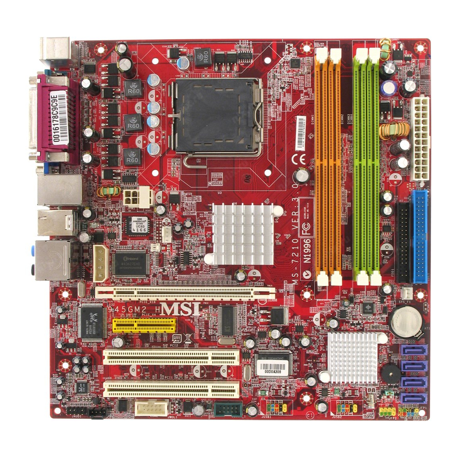
Page 14: Mainboard Layout
M S-7210 Micro-ATX Mainboard Top : mouse Bottom: keyboard Top : Parallel Port Bottom: COM 1 VGA Port JPW1 T: LAN jack B: USB ports T: 1394 port (optional) BIOS B: USB ports JPWR1 JCI1 Line-I n Line-Ou t Wi nbon d W836 27EHF T: RS -Out M:CS... -
Page 15: Getting Started
Top : mouse Bottom: keyboard Top : Parallel Port Bottom: COM 1 JPW1 T: LAN jack B: USB ports CPU_F2 T: 1394 port BIOS B: USB ports JPWR1 JCI1 Line-I n Line-Ou t Wi nbon d W836 27EHF T: RS -Out BIOS_WP M:CS -Out... -
Page 16: Packing Contents
M S-7210 Micro-ATX Mainboard Packing Contents MSI Driver/Utility CD SATA Cable MSI motherboard Standard Cable for Standard Cable for Power Cable Floppy Disk IDE Devices IEEE1394-Bracket USB Bracket (Optional) Back IO Shield (Optional) * The pictures are for reference only and may vary f rom the pac king c ontents of the product you User’s Guide... -
Page 17: Chapter 2. Hardware Setup
Chapter 2. Hardware Setup Hardware Setup This chapter tells you how to install the CPU, memory modules, and expansion cards, as well as how to setup the jumpers on the mainboard. Also, it provides the instructions on connecting the periph- eral devices, such as the mouse, keyboard, etc. -
Page 18: Quick Components Guide
M S-7210 Micro-ATX Mainboard Quick Components Guide JPWR1, p.2-9 JPW1, p.2-9 Back Panel, p. 2-10 BIOS_WP, p.2-21 PCIE_X16, p.2-22 PCIE_X4, p.2-22 PCI 1/2, p.2-23 JAUD1, p.2-18 JCD1, p.2-17 CPU, p.2-3 JCI1, p2-20 CPU_F2, p2-14 Int el 945G JWOL1, JUSB1/2, p.2-20 p.2-18 J1394, COM2,... -
Page 19: Central Processing Unit: Cpu
CPU, make sure to install the cooler to prevent overheating. If you do not have the CPU cooler, contact your dealer to purchase and install them before turning on the computer. For the latest information about CPU, please visit http://www.msi.com.tw/pro- gram/products/mainboard/mbd/pro_mbd_cpu_support.php. MSI Reminds You... -
Page 20: Cpu & Cooler Installation
3. Use 2 hands to remove the land side cover (if any). Please note not to touch the pins. MSI Reminds You... 1. Confirm if your CPU cooler is firmly installed before turning on your system. 2. Do not touch the CPU socket pins to avoid damaging. - Page 21 5. The CPU has a plastic cap on it to protect the contact from damage. Before you have installed the CPU, always cover it to protect the socket pin. 7. Lift the load lever up and open the load plate. 9.
- Page 22 15. Turn over the mainboard to confirm that th e c li p-en ds are c orrec tly inserted. MSI Reminds You... 1. Check the information in PC Health Status of H/W M onitor in BIOS (Chapter 3) for the CPU temperature.
-
Page 23: Memory
DDR2 memory module in the DDR2 slot. Otherwise, you are not able to boot up your system and your mainboard might be damaged. For the updated supporting memory modules, please visit http://www.msi. com.tw/program/products/mainboard/mbd/pro_mbd_trp_list.php. Introduction to DDR2 SDRAM DDR2 is a new technology of memory module, and its speed is the top limit of current DDR1 technology. -
Page 24: Installing Ddr2 Modules
256MB~1GB 256MB~1GB 256MB~1GB 256MB~1GB MSI Reminds You... - Dual-channel DDR2 works ONLY in the 5 combinations listed in the table shown in the previous page. - Please select the identical memory modules to install on the dual channel, and DO NOT install three memory modules on three DIMMs, or it may cause some failure. -
Page 25: Power Supply
JPW1 Pin Definition PIN SIGNAL JPW1 MSI Reminds You... 1. These three connectors connect to the ATX power supply and have to work together to ensure stable operation of the mainboard. 2. Power supply of 400 watts (and above) is highly recommended for system stability. -
Page 26: Mouse/Keyboard Connector
M S-7210 Micro-ATX Mainboard The back panel provides the following connectors: Parallel M ou se COM Port Keyboard Mouse/Keyboard Connector The mainboard provides a standard PS/2 ® for attaching a PS/2 mouse/keyboard. You can plug a PS/2 into this connector. The connector location and pin assignments are as follows: PS/2 Mouse / Keyboard (6-pin Female) Serial Port Connector: COM Port... -
Page 27: Ieee 1394 Port
VGA Connector (for 945G only) The mainboard provides a DB 15-pin female connector to connect a VGA monitor. VGA Connector (DB 15-pin) USB Connectors The mainboard provides an OHCI (Open Host Controller Interface) Universal Serial Bus root for attaching USB devices such as keyboard, mouse or other USB- compatible devices. -
Page 28: Lan (Rj-45) Jack
(Surround R/L) (in 7.1 CH) Line Out (Front R/L) M IC MSI Reminds You... For the advanced functions of the audio codec, please refer to Chapter 6: Introduction to Realtek ALC880 Audio Codec for details. 2-12 Giga-bit LAN Pin Definition... -
Page 29: Parallel Port Connector: Lpt1
Parallel Port Connector: LPT1 The mainboard provides a 25-pin female centronic connector as LPT. A parallel port is a standard printer port that supports Enhanced Parallel Port (EPP) and Ex- tended Capabilities Parallel Port (ECP) mode. Pin Definition SIGNAL DESCRIPTION STROBE Strobe DATA0... -
Page 30: Floppy Disk Drive Connector: Fdd1
System Hardware Monitor chipset on-board, you must use a spe- cially designed fan with speed sensor to take advantage of the CPU fan control. CPU_F2 MSI Reminds You... 1. Always consult the vendors for proper CPU cooling fan. 2. Please refer to the recommended CPU fans at Intel website. -
Page 31: Hard Disk Connector: Ide1
The IDE1 can connect a Master and a Slave drive. You must configure second hard drive to Slave mode by setting the jumper accordingly. MSI Reminds You... If you install two hard disks on cable, you must configure the second drive to Slave mode by setting its jumper. -
Page 32: Serial Ata Connectors Controlled By Intel Ich7/ Ich7R: Sata1~Sata4
SATA3 SATA1 Serial ATA cable Connect to serial ATA ports MSI Reminds You... Please do not fold the serial ATA cable in a 90-degree angle, since this might cause the loss of data during the transmission. 2-16 SATA1~ SATA4 Pin Definition... -
Page 33: Cd-In Connector: Jcd1
CD-In Connector: JCD1 The connector is for CD-ROM audio connector. JCD1 Front Panel Connectors: JFP1 / JFP2 The mainboard provides two front panel connectors for electrical connection to the front panel switches and LEDs. JFP1 is compliant with Intel Connectivity Design Guide. Power Power Switch... -
Page 34: Front Usb Connectors: Jusb1 / Jusb2
USB interface peripherals such as USB HDD, digital cameras, MP3 players, printers, modems and the like. JUSB1 / JUSB2 (USB 2.0/standard spec) MSI Reminds You... Note that the pins of VCC and GND must be connected correctly, or it may cause some damage. Front Panel Audio Connector: JAUD1... -
Page 35: Ieee 1394 Connector: J1394_1 (Optional)
IEEE 1394 Connector: J1394_1 (Optional) The mainboard provides one 1394 pin header that allow you to connect optional IEEE 1394 port. J1394_1 How to attach the IEEE 1394 Port: Connected to J1394_1 (Green connector) Foolproof design Pin Definition SIGNAL TPA+ Ground TPB+ Cable power... -
Page 36: Chassis Intrusion Switch Connector: Jci1
M S-7210 Micro-ATX Mainboard Serial Port Header: COM2 (Optional) The mainboard offers one 9-pin header as serial port. The port is a 16550A high speed communication port that sends/receives 16 bytes FIFOs. You can attach a serial mouse or other serial device directly to it. COM2 Chassis Intrusion Switch Connector: JCI1 This connector is connected to a 2-pin chassis switch. -
Page 37: Jumpers
The motherboard provides the following jumper for you to set the computer’s function. This section will explain how to change your motherboard’s function through the use of jumpers. Clear CMOS Jumper: JBAT1 There is a CMOS RAM on board that has a power supply from external battery to keep the system configuration data. -
Page 38: Slots
M S-7210 Micro-ATX Mainboard The mainboard provides a PCI Express x16 slot, a PCI Express x4 slot and three 32-bit PCI bus slots. PCI Express Slots (optional) The PCI Express slots, as a high-bandwidth, low pin count, serial, intercon- nect technology, support Intel highest performance desktop platforms utilizing the Intel Pentium 4 processor with HT Technology. -
Page 39: Pci (Peripheral Component Interconnect) Slots
PCI (Peripheral Component Interconnect) Slots The PCI slots allow you to insert the expansion cards to meet your needs. W hen adding or removing expansion cards, make sure that you unplug the power supply first. Meanwhile, read the documentation for the expansion card to make any necessary hardware or software settings for the expansion card, such as jumpers, switches or BIOS configuration. -
Page 40: Chapter 3. Bios Setup
SETUP. ² You want to change the default settings for customized features. MSI Reminds You... 1. The items under each BIOS category described in this chapter are under continuous update for better system performance. Therefore, the description may be slightly different from the latest BIOS and should be held for reference only. -
Page 41: Entering Setup
M S-7210 Micro-ATX Mainboard Power on the computer and the system will start POST (Power On Self Test) process. W hen the message below appears on the screen, press <DEL> key to enter Setup. Press DEL to enter SET UP If the message disappears before you respond and you still wish to enter Setup, restart the system by turning it OFF and On or pressing the RESET button. -
Page 42: Getting Help
Getting Help After entering the Setup menu, the first menu you will see is the Main Menu. M ain M enu The main menu lists the setup functions you can make changes to. You can use the control keys ( ) to select the item. -
Page 43: Standard Cmos Features
M S-7210 Micro-ATX Mainboard The Main Menu ® Once you enter AMI BIOS CMOS Setup Utility, the Main Menu will appear on the screen. The Main Menu allows you to select from several setup functions and two exit choices. Use arrow keys to select among the items and press <Enter> to accept or enter the sub-menu. - Page 44 BIOS Setup Load Optimized Defaults Use this menu to load the default values set by the mainboard manufacturer specifi- cally for optimal performance of the mainboard. BIOS Setting Password Use this menu to set the Password. Save & Exit Setup Save changes to CMOS and exit setup.
-
Page 45: Standard Cmos Features
M S-7210 Micro-ATX Mainboard Standard CMOS Features The items in Standard CMOS Features Menu are divided into several categories. Each category includes no, one or more than one setup items. Use the arrow keys to highlight the item and then use the <PgUp> or <PgDn> keys to select the value you want in each item. - Page 46 Device/ Vender/ Size It will showing the device information that you connected to the IDE/SATA con- nector . LBA/Large M ode This allows you to enable or disable the LBA Mode. Setting to Auto enables LBA mode if the device supports it and the devices is not already formatted with LBA mode disabled.
- Page 47 M S-7210 Micro-ATX Mainboard System Information Press <Enter> to enter the sub-menu and the following screen appears: Total System M emory/ BIOS Version/ CPU Information The items show the CPU information, BIOS version and memory status of your system (read only).
-
Page 48: Advanced Bios Features
BIOS Setup Advanced BIOS Features Quick Boot Select Enabled to reduce the amount of time required to run the power-on self-test (POST). A quick POST skips certain steps. We recommend that you normally disable quick POST. It is better to find a problem during POST than lose data during your work. Setting options: [Enabled], [Disabled]. - Page 49 M S-7210 Micro-ATX Mainboard Execute Disable Bit Execute Disable Bit is designed for memory buffer overflow protection, it can prevent viruses from proliferating. Setting options: [Enabled], [Disabled]. IOAPIC Function This field is used to enable or disable the APIC (Advanced Programmable Interrupt Controller).
-
Page 50: Advanced Chipset Features
Advanced Chipset Features MSI Reminds You... Change these settings only if you are familiar with the chipset. Configure DRAM Timing by SPD Selects whether DRAM timing is controlled by the SPD (Serial Presence Detect) EEPROM on the DRAM module. Setting to [Auto] enables DRAM timings and the fol- lowing related items to be determined by BIOS based on the configurations on the SPD. - Page 51 M S-7210 Micro-ATX Mainboard DRAM RAS# Precharge This item controls the number of cycles for Row Address Strobe (RAS) to be allowed to precharge. If insufficient time is allowed for the RAS to accumulate its charge before DRAM refresh, refresh may be incomplete and DRAM may fail to retain data. This item applies only when synchronous DRAM is installed in the system.
-
Page 52: Integrated Peripherals
BIOS Setup Integrated Peripherals USB Controller This setting disables/enables theUSB controller. Setting options: [Enabled], [Disabled]. USB Device Legacy Support Set to Enabled if your need to use any USB 1.1/2.0 device in the operating system that does not support or have any USB 1.1/2.0 driver installed, such as DOS and SCO Unix. - Page 53 M S-7210 Micro-ATX Mainboard On-Chip ATA Device Press <Enter> to enter the sub-menu and the following screen appears: PCI IDE BusM aster This item allows you to enable/ disable the PCI IDE busmaster. Setting options: [Disabled], [Enabled]. ATA/IDE Configuration This item is used to specify the SATA & IDE devices. The setting options are: Compatible You can use the IDE channels with the SATA devices and IDE devices.
- Page 54 I/O Devices Configuration Press <Enter> to enter the sub-menu and the following screen appears: OnBoard Floppy Controller This item allows you to enable/ disable the floppy controller. Setting options: [Disabled], [Enabled]. COM Port 1/ 2 Select an address and corresponding interrupt for Serial Port 1/ 2. Setting options: [3F8/IRQ4], [2E8/IRQ3], [3E8/IRQ4], [2F8/IRQ3], [Disabled].
-
Page 55: Power Management Setup
M S-7210 Micro-ATX Mainboard Power Management Setup MSI Reminds You... S3-related functions described in this section are available only when your BIOS supports S3 sleep mode. ACPI Function This item is to activate the ACPI (Advanced Configuration and Power Management Interface) Function. - Page 56 Re-Call VGA BIOS from S3 W hen ACPI Standby State is set to [S3/STR], users can select the options in this field. Selecting [Enabled] allows BIOS to call VGABIOS to initialize the VGA card when system wakes up (resumes) from S3 sleep state. The system resume time is shortened when you disable the function, but system will need an AGP driver to initialize the VGA card.
- Page 57 M S-7210 Micro-ATX Mainboard Resume By PS/2 M ouse This setting only works Resume By PS/2 KB is set to [Hot Key]. This setting determines whether the system will be awakened from what power saving modes when input signal of the PS/2 mouse is detected. Setting options: [Disabled], [Enabled].
-
Page 58: Pnp/Pci Configurations
PNP/PCI Configurations This section describes configuring the PCI bus system and PnP (Plug & Play) feature. PCI, or Peripheral Component Interconnect, is a system which allows I/O devices to operate at speeds nearing the speed the CPU itself uses when communi- cating with its special components. - Page 59 [Reserved], and IRQ 14/15 are allocated to the onboard PCI IDE, IRQ 9 will still be available for PCI and PnP devices. Available settings: [Reserved] and [Available]. MSI Reminds You... IRQ (Interrupt Request) lines are system resources allocated to I/O devices. When an I/O device needs to gain attention of the operating system, it signals this by causing an IRQ to occur.
- Page 60 DM A Resource Setup Press <Enter> to enter the sub-menu and the following screen appears. DMA Channel 0/1/3/5/6/7 These items specify the bus that the system DMA (Direct Memory Access) channel is using. The settings determine if AMIBIOS should remove a DMA from the available DMAs passed to devices that are configurable by the system BIOS.
-
Page 61: H/W Monitor
Monitor function is available only if there is hardware monitoring mechanism onboard. Spread Spectrum W hen the motherboard’s clock generator pulses, the extreme values (spikes) of the pulses creates EMI (Electromagnetic Interference). The Spread Spectrum function reduces the EMI generated by modulating the pulses so that the spikes of the pulses are reduced to flatter curves. - Page 62 BIOS Setup Chassis Intrusion The field enables or disables the feature of recording the chassis intrusion status and issuing a warning message if the chassis is once opened. To clear the warning message, set the field to [Reset]. The setting of the field will automatically return to [Enabled] later.
-
Page 63: Load Optimized Defaults
M S-7210 Micro-ATX Mainboard Load Optimized Defaults The option on the main menu allow users to restore all of the BIOS settings to the default Optimized values. The Optimized Defaults are the default values set by the mainboard manufacturer specifically for optimal performance of the mainboard. W hen you select Load Optimized Defaults, a message as below appears: Pressing [Y] loads the default factory settings for optimal system performance. -
Page 64: Bios Setting Password
BIOS Setting Password W hen you select this function, a message as below will appear on the screen: Type the password, up to six characters in length, and press <Enter>. The password typed now will replace any previously set password from CMOS memory. You will be prompted to confirm the password. -
Page 65: Chapter 4. Introduction To Digicell
Chapter 4. Introduction to DigiCell Introduction to DigiCell DigiCell, the most useful and powerful utility that MSI has spent much research and efforts to develop, helps users to monitor and configure all the integrated peripherals of the system, such as audio program, power management, MP3 files management and communication / 802.11g W LAN... -
Page 66: Main
Introduction: Click on each icon appearing above to enter the sub-menu to make further configuration. M SI Click on this button to link to MSI website: http://www.msi.com.tw. Quick Guide Click on this button and the quick guide of DigiCell will be displayed for you to review. - Page 67 Power on Agent In this sub-menu, you can configure date, time and auto-executed programs of the power-on, power-off and restarting features. MSI Reminds You... Click on back button in every sub-menu and it will bring you back to the main menu.
-
Page 68: H/W Diagnostic
In the H/W Diagnostic sub-menu, you can see the information, status and note of each DigiCell. You may double check the connection and installation of the item marked as gray. You may also click on the Mail to MSI button to send your questions or suggestions to MSI’s technical support staff. -
Page 69: Communication
In the Communication sub-menu, you can see the status of all the LAN / W LAN / Bluetooth on the screen if the hardware is installed. The first icon indicates the onboard LAN on your system, the second icon indicates the wireless LAN status, and the third one is the information about the bluetooth on your system. -
Page 70: Software Access Point
M S-7210 Micro-ATX Mainboard Software Access Point In the Software Access Point sub-menu, you can see the communication status on your system and choose the desired software access point mode by clicking on the desired icon, in which the default settings are configured for your usage. The default software access point mode is set to WLAN Card M ode. -
Page 71: Access Point Mode
Access Point Mode Click on “Setting” button of the Access Point Mode and the following screen will display. IP Sharing Click on this icon to enable/disable the IP sharing. The default of this setting is disabled. Disabled. Enabling/disabling IP sharing depends on the different situation. For example: 1. -
Page 72: Wlan Card Mode
M S-7210 Micro-ATX Mainboard Association Control This option allows you to control which PC can connect to the wireless LAN. If you enable this feature, only PCs with MAC address located in Association Control List can connect to the wireless LAN. M AC Address MAC stands for Media Access Control. -
Page 73: Live Update
BIOS/VGA Driver/Utility online so that you don’t need to search for the correct BIOS/driver version throughout the whole W eb site. To use the function, you need to install the “MSI Live Update 3” application. After the installation, the “MSI Live Update 3”... -
Page 74: Mega Stick
M S-7210 Micro-ATX Mainboard In the MEGA STICK sub-menu, you can configure the settings of MSI MEGA STICK and the media files (*.m3u, *.mp3, *.wav, *.cda, *.wma) on your system. Basic Function Here you can edit your own play list with the buttons “load”, “save”, “delete”, “shuttle”, “repeat”... - Page 75 There is also a toolbar for you to execute some basic function, like play, stop, pause, previous/next song, song info and volume adjust. There is also a scroll bar on the top for you to forward/rewind. pause previous stop Right-click on the MP3 file and choose “Info”, a MP3 Info dialogue will pop up to show the information of the file, including the title, artist, album, release year and others.
-
Page 76: Non-Unicode Programs Supported
M S-7210 Micro-ATX Mainboard Non-Unicode programs supported If you are using an operating system in European languages, and you’d like to play the media files in MEGA STICK with East-Asian languages (such as Chinese, Japanese... etc.), it is possible that the file names display incorrectly. However, you can ins tall the Supplemental Language Support provided by Microsoft to solve this problem. - Page 77 Introduction to DigiCell 3. Then go to the [Advanced] tab and select the language you want to be supported (the language of the filename in the MegaStick) from the drop- down list in the [Language for non-Unicode programs], then click [Apply]. The system will install the necessary components from your Microsoft Setup CD immediately.
-
Page 78: V-Center
M S-7210 Micro-ATX Mainboard V-Center Click on the V-Center icon in the main menu and the V-Center program will be enabled. V-Center is just like your PC doctor that can detect, view the CPU & system tempera- ture and Vcore voltage. Stable - Click on this icon, it will automatic configure the stable values for the system. -
Page 79: Power On Agent
Click “OK” to restart the computer right away or click “Later” to restart your computer later. MSI Reminds You... Please note that the new setting will not take effect until you restart your computer. -
Page 80: Power Off / Restart
Of course you may use the button “-Delete” to remove the added programs, or you can right-click on the selected program and click Delete. MSI Reminds You... You can also enable the Every turn on function, which will enable the specified program(s) and file(s) every time the Digi Cell utility runs. -
Page 81: Auto Login
Auto Login Since the Power On function allows the system to power on automatically, you may have to enable this Auto Login function in the following situations: 1. If you are using a computer belonging to a domain in office, and you need to enter your user name &... -
Page 82: Chapter 5. Introduction To Intel Ich7R Sata Raid
Technology is the advanced ability for two RAID volumes to share the combined space of two hard drives being used in unison. MSI Reminds You... The minimum number of hard drives for RAID 0, RAID 1 or Matrix mode is 2. The minimum number of hard drives for RAID 10 mode is 4. And the minimum number of hard drives for RAID 5 mode is 3. -
Page 83: Bios Configuration
Intel RAID Option ROM. During the Power-On Self Test (POST), the following message will appear for a few seconds: MSI Reminds You... The “Driver Model”, “Serial #” and “Size” in the following example might be different from your system. - Page 84 After pressing the <Ctrl> and <I> keys simultaneously, the following window will appear: (1) Create RAID Volume Select option 1 “Create RAID Volume” and press <Enter> key. The following screen appears. Then in the Name field, specify a RAID Volume name and then press the <TAB>...
- Page 85 M S-7210 Micro-ATX Mainboard In the Disk field, press <Enter> key and the following screen appears. Use <Space> key to select the disks you want to create for the RAID volume, then click <Enter> key to finish selection. Then select the strip value for the RAID array by using the “upper arrow” or “down arrow”...
- Page 86 MSI Reminds You... Since you want to create two volumes (Intel Matrix RAID Technology), this default size (maximum) needs to be reduced. Type in a new size for the first volume. As an example: if you want the first volume to span the first half of the two disks, re-type the size to be half of what is shown by default.
- Page 87 Here you can delete the RAID volume, but please be noted that all data on RAID drives will be lost. MSI Reminds You... If your system currently boots to RAID and you delete the RAID volume in the Intel RAID Option ROM, your system will become unbootable.
- Page 88 RAID structures from the drives. The following screen appears: Press <Y> key to accept the selection. MSI Reminds You... 1. You will lose all data on the RAID drives and any internal RAID structures when you perform this operation.
-
Page 89: Installing Software
Windows XP/2000 installation. † Existing Windows XP/2000 Driver Installation 1. Insert the MSI CD into the CD-ROM drive. 2. The CD will auto-run and the setup screen will appear. 3. Under the Driver tab, click on Intel IAA RAID Edition. -
Page 90: Installation Of Intel Matrix Stroage Console
For this reason, you cannot remove or un-install this driver from the system after installation; however, you will have the ability to un-install all other non-driver components. Insert the MSI CD and click on the Intel IAA RAID Edition to install the software. Click on this item 5 - 9... - Page 91 M S-7210 Micro-ATX Mainboard The InstallShield Wizard will begin automatically for installation showed as following: Click on the Next button to proceed the installation in the welcoming window. 5-10...
- Page 92 Introduction to Intel ICH7R SATA RAID The window shows the components to be installed. Click Next button to continue. After reading the license agreement in the following window, click Yes button to continue. 5-11...
- Page 93 M S-7210 Micro-ATX Mainboard Select the folder in which you want the program to be installed in the following window, and click Next button to start installation. Select a program folder in the following window where you want Setup to add the program icon.
- Page 94 Introduction to Intel ICH7R SATA RAID The following window appears to show the Intel Application Accelerator RAID Edition Setup installation status. Once the installation is complete, the following window appears. 5-13...
-
Page 95: Raid Migration Instructions
3. Install the Intel Matrix Storage Console after the operating system is installed. To create a volume from an existing disk, complete the following steps: MSI Reminds You... A Create from Existing Disk operation will delete all existing data from the added disk and the data cannot be recovered. It is critical to backup all important data on the added disk before proceeding. -
Page 96: Create Raid Volume From Existing Disk
Introduction to Intel ICH7R SATA RAID Create RAID Volume from Existing Disk To create a RAID volume from an existing disk, choose Action --> Create RAID Volume from Existing Hard Drive. The Create RAID Volume from Existing Hard Drive Wizard pops up to lead you for the following procedure. - Page 97 M S-7210 Micro-ATX Mainboard (1) Step 1: Configure Volume Here you can configure the new RAID volume by entering the volume name, selecting the RAID level and strip size. † RAID Volume Name: A desired RAID volume name needs to be typed in where the ‘RAID_Volume0’ text currently appears above.
- Page 98 RAID 10 (Mirrored Stripes) – A RAID 1 array of two RAID 0 arrays. † Strip Sizes: Select the desired strip size setting. As indicated, the optimal setting is 128KB. Se- lecting any other option may result in performance degradation. Even though 128KB is the recommended setting for most users, you should choose the strip size value which is best suited to your specific RAID usage model.
- Page 99 M S-7210 Micro-ATX Mainboard (3) Select Member Hard Drive(s) Then select the member disk (the target disk) that you wish to use and then click “--->” to move it to the Selected field. Then click Next to continue. Please note that the existing data on the selected hard drive(s) will be deleted permanently.
- Page 100 (4) Specify Volume Size Specify the amount of available array space to be used by the new RAID volume. You may enter the amount in the space or use the slider to specify. It is recommended you use 100% of the available space for the optimized usage. For RAID 0 volume, if you do not specify 100% of the hard drive space, the rest hard drive space will be worked as RAID 1 volume, which is the new technology called Intel Matrix RAID.
- Page 101 M S-7210 Micro-ATX Mainboard (6) Start Migration The migration process may take up to two hours to complete depending on the size of the disks being used and the strip size selected. A dialogue window will appear stating that the migration process may take considerable time to complete, meanwhile a popup dialogue at the taskbar will also show the migration status.
-
Page 102: Chapter 6. Itroduction To Realtek
Chapter 6. Introduction to Realtek Chapter 6. Itroduction to Realtek ALC880 ALC880 Realtek ALC880 The mainboard is equipped with Realtek ALC880 chip, which provides support for 8-channel audio output, including 2 Front, 2 Rear, 2 Side, 1 Center and 1 Subwoofer channel. ALC880 allows the board to attach 2, 4, 6 or 8 speakers for better surround sound effect. -
Page 103: Installation For Windows 2000/Xp
1. Insert the companion CD into the CD-ROM drive. The setup screen will automatically appear. 2. Click Realtek HD Audio Driver. MSI Reminds You... The HD Audio Configuration continuous update to enhance audio applications. Hence, the program screens shown here in this appendix may be slightly different from the latest software utility and shall be held for reference only. - Page 104 3. Click Next to install the Realtek High Definition Audio Driver. 4. Click Finish to restart the system. Introduction to Realtek ALC880 Clic k he r e Se le ct this o ptio n Clic k he r e...
-
Page 105: Software Configuration
M S-7210 Micro-ATX Mainboard Software Configuration After installing the audio driver, you are able to use the 2-, 4-, 6- or 8- channel audio feature now. Click the audio icon from the system tray at the lower-right corner of the screen to activate the HD Audio Configuration. It is also available to enable the audio driver by clicking the Azalia HD Sound Effect Manager from the Control Panel. -
Page 106: Sound Effect
Sound Effect Here you can select a sound effect you like from the Environment list. You may choose the provided sound effects, and the equalizer will adjust automatically. If you like, you may also load an equalizer setting or make a new equalizer setting to save as a new one by using the “Load EQ Setting”... - Page 107 M S-7210 Micro-ATX Mainboard Equalizer Selection Equalizer frees users from default settings; users may create their owned preferred settings by utilizing this tool. 10 bands of equalizer, ranging from 100Hz to 16KHz. Save The settings are saved permanently for future use.
- Page 108 Frequently Used Equalizer Setting Realtek recognizes the needs that you might have. By leveraging our long experience at audio field, Realtek HD Audio Sound Manager provides you certain optimized equal- izer settings that are frequently used for your quick enjoyment. [How to Use It] Other than the buttons “Pop”...
-
Page 109: Mixer
Realtek HD Audio rear output or Realtek HD Audio front output items. MSI Reminds You... Before set up, please make sure the playback devices are well plugged in the jacks on the rear or front panel. The Realtek HD Audio front output item will appear after you pluging the speakers into the jacks on the front panel. - Page 110 W hen you are playing the first audio source (for example: use W indows Media Player to play DVD/VCD), the output will be played from the rear panel, which is the default setting. Then you must to select the Realtek HD Audio 2nd output from the scroll list first, and use a different program to play the second audio source (for example: use W inamp to play MP3 files).
- Page 111 M S-7210 Micro-ATX Mainboard 3. Playback control Tool Mute M u te You may choose to mute single or multiple volume controls or to completely mute sound output. Tool Show the following volume control This is to let you freely decide which volume control items to be displayed, total 13 items to be chosen.
- Page 112 If you’d like to connect your microphone to the front audio panel. You may control the microphone volume by Mic Volume or front mic-in on the mixer. MSI Reminds You... If you intend to record by via two microphones, please note that you have to check the “Stereo Mix”...
-
Page 113: Audioio
M S-7210 Micro-ATX Mainboard AudioIO In this tab, you can easily configure your multi-channel audio function and speakers. You can choose a desired multi-channel operation here. a. Headphone for the common headphone b. 2CH Speaker for Stereo-Speaker Output c. 4CH Speaker for 4-Speaker Output d. - Page 114 Correct M essage Assume to plug a headphone in the Green jack at back panel. The icon beside green jack become visible and the dialogue “connected device” pops up. Check the headphone, then click OK. As soon as OK is clicked, the icon beside green jack becomes “headphone”...
- Page 115 M S-7210 Micro-ATX Mainboard Global Connector Settings Click to access global connector settings. 1. M ute rear panel when front headphone plugged in Once this item is checked, whenever front headphone is plugged, the music that is playing from the back panel, will be stopped. 2.
- Page 116 S/PDIF Short for Sony/Philips Digital Interface, a standard audio file transfer format. S/ PDIF allows the transfer of digital audio signals from one device to another without having to be converted first to an analog format. Maintaining the viability of a digital signal prevents the quality of the signal from degrading when it is converted to analog.
- Page 117 M S-7210 Micro-ATX Mainboard Test Speakers You can select the speaker by clicking it to test its functionality. The one you select will light up and make testing sound. If any speaker fails to make sound, then check whether the cable is inserted firmly to the connector or replace the bad speakers with good ones.
-
Page 118: Microphone
Introduction to Realtek ALC880 Microphone In this tab you may set the function of the microphone. Select the Noise Suppression to remove the possible noise during recording, or select Acoustic Echo Cancelltion to cancel the acoustic echo druing recording 6-17... -
Page 119: 3D Audio Demo
M S-7210 Micro-ATX Mainboard 3D Audio Demo In this tab you may adjust your 3D positional audio before playing 3D audio applications like gaming. You may also select different environment to choose the most suitable environment you like. 6-18... -
Page 120: Information
Introduction to Realtek ALC880 Information In this tab it provides some information about this HD Audio Configuration utility, including Audio Driver Version, DirectX Version, Audio Controller & Audio Codec. You may also select the language of this utility by choosing from the Language list. Also there is a selection Show icon in system tray. -
Page 121: Using 2-, 4-, 6- & 8- Channel Audio Function
M S-7210 Micro-ATX Mainboard Using 2-, 4-, 6- & 8- Channel Audio Function Connecting the Speakers W hen you have set the Multi-Channel Audio Function mode properly in the software utility, connect your speakers to the correct phone jacks in accordance with the setting in software utility. - Page 122 n 4-Channel M ode for 4-Speaker Output Back Panel 4-Channel Analog Audio Output Line In Line Out (Front channels) Line Out (Rear channels) Line Out (Center and Subwoofer channel, but no functioning in this mode) S/PDIF Out-Optical Introduction to Realtek ALC880 Description: Connect two speakers to back panel’s Line Out connector and...
- Page 123 M S-7210 Micro-ATX Mainboard n 6-Channel M ode for 6-Speaker Output Back Panel 6-Channel Analog Audio Output Line In Line Out (Front channels) Line Out (Rear channels) Line Out (Center and Subwoofer channel) S/PDIF Out-Optical 6-22 Description: Connect two speakers to back panel’s Line Out connector, two speakers to the rear-channel Line out connector Line out con-...
- Page 124 n 8-Channel M ode for 8-Speaker Output Back Panel 8-Channel Analog Audio Output Side Surround Out (Side channels) Line Out (Front channels) Line Out (Rear channels) Line Out (Center and Subwoofer channel) S/PDIF Out-Optical Introduction to Realtek ALC880 Description: Connect two speakers to back panel’s Line Out connector, two speakers to the rear-channel Line out connector, two speak-...
Need help?
Do you have a question about the 945GM2-FR and is the answer not in the manual?
Questions and answers