
Related Manuals for Panametrics HydroProII


Summary of Contents for Panametrics HydroProII
- Page 1 HygroPro Moisture Transmitter User’s Manual 910-331 A panametrics.com November 2022...
- Page 3 User’s Manual 910-331 A November 2022 panametrics.com Copyright 2022 Baker Hughes company. This material contains one or more registered trademarks of Baker Hughes Company and its subsidiaries in one or more countries. All third-party product and company names are trademarks of their respective...
- Page 4 [no content intended for this page]...
-
Page 5: Table Of Contents
Contents Chapter 1. Installation Introduction ..................... .1 Sample System Guidelines . - Page 6 Contents Appendix A. HygroPro HART® Field Device Specification Introduction ....................41 A.1.1 Scope .
- Page 7 Contents Device-Specific Commands..................47 A.9.1 Command 130 (0x82): Set Loop Trim Zero .
- Page 8 Contents Appendix B. HygroPro Field Service Update User Manual Setup ......................77 B.1.1 Required Tools .
- Page 9 Services Panametrics provides customers with an experienced staff of customer support personnel ready to respond to technical inquiries, as well as other remote and on-site support needs. To complement our broad portfolio of industry-leading solutions, we offer several types of flexible and scalable support services including: Training, Product Repairs, Service Agreements and more.
- Page 10 Preface Auxiliary Equipment Local Safety Standards The user must make sure that he operates all auxiliary equipment in accordance with local codes, standards, regulations, or laws applicable to safety. Working Area WARNING! Auxiliary equipment may have both manual and automatic modes of operation. As equipment can move suddenly and without warning, do not enter the work cell of this equipment during automatic operation, and do not enter the work envelope of this equipment during manual operation.
- Page 11 Preface Environmental Compliance RoHS The HygroPro moisture transmitter fully complies with RoHS regulations (Directive 2011/65/EU). Waste Electrical and Electronic Equipment (WEEE) Directive Baker Hughes is an active participant in Europe’s Waste Electrical and Electronic Equipment (WEEE) take-back initiative (Directive 2012/19/EU). This equipment has required the extraction and use of natural resources for its production.
- Page 12 Preface [no content intended for this page] HygroPro User's Manual...
-
Page 13: Chapter 1. Installation
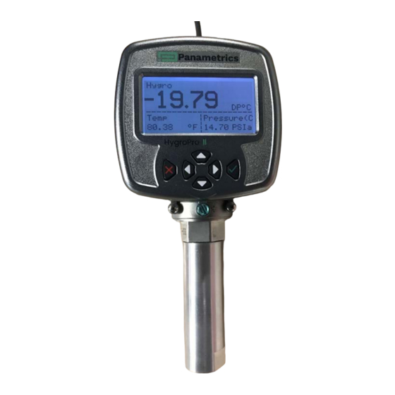
Chapter 1. Installation Chapter 1. Installation Introduction The HygroPro moisture transmitter is a compact, intrinsically safe, loop-powered, 4–20 mA transmitter that provides accurate dew/frost point measurements over a range of –110°C to 20°C (-166°F to 68°F). It features an integrated display and a six-button keypad, and is housed in an IP66/67, NEMA 4X rated enclosure. -
Page 14: Sample System Guidelines
Sample System Guidelines The HygroPro transmitter can be installed in a sample system or directly in the process line. However, Panametrics recommends that the transmitter be installed in a sample system to protect the sensor probe from potentially damaging components in the process stream. Figure 2 below shows a typical sample system. -
Page 15: Mounting The Transmitter
Mounting the Transmitter CAUTION! If the HygroPro will be installed directly into the process line, consult Panametrics for proper installation instructions and precautions before proceeding. Refer to Figure 3 below and complete the steps on the next page to install the HygroPro transmitter. - Page 16 Chapter 1. Installation Note: Do not unscrew and remove the metal desiccant cap from the probe until just prior to installation of the probe in the process. Note: If there is insufficient space to rotate the HygroPro during installation, remove the Replaceable Transducer Element (RTE) from the transmitter, install it in the fitting, then re-install the transmitter display onto the RTE.
-
Page 17: Wiring The Transmitter
Chapter 1. Installation Step 3: Install the HygroPro into the process by threading it into the sampling port or sample cell. Please note the transmitter should be tightened using a 1-1/8” wrench only on the hex nut of the probe until it is sealed on the O-ring surface. -
Page 18: Standard Connections To Process Controller Via Analog Output
Chapter 1. Installation A Highway Addressable Remote Transducer (HART) communicator (handheld device or plant control system) that can communicate digitally with the HART enabled HygroPro transmitter over the same two wires as used for the analog output in either a point-to-point or multi-drop configuration) An external power supply to provide power to the HygroPro plus a personal computer (PC) running TeraTerm or other terminal emulator that can used for field upgrade of the HygroPro firmware (proceed to page 9) -
Page 19: Standard Connection With A Hart Master (Handheld Device Or Control System)
Chapter 1. Installation Push the keyed female M8 connector end of the factory-supplied standard (black) cable into the mating bulkhead connector on the back of the transmitter module. Make sure the pins are properly aligned using the key in the female connector. Then, secure the connectors together by sliding the metal sleeve on the female connector over the bulkhead connector and turning it clockwise until it is tight. -
Page 20: Standard Connections With A Pc For Field Software Upgrade
Chapter 1. Installation 1.4.1.3 Standard Connections with a PC for field software upgrade Refer to Figure 9 on the next page and Table 2 below, and complete the following steps to wire the transmitter. Table 2: Cable Leads - With a PC Lead Connection Description Blue... -
Page 21: Hazardous Area Wiring Connections
Chapter 1. Installation 1.4.2 Hazardous Area Wiring Connections Before installing and using the HygroPro in a hazardous (classified) area, be sure to read and understand all applicable reference materials. This includes: • all EU or North American Standards and Directives (see Table 3 and Table 4 on page 11) •... - Page 22 Chapter 1. Installation • With appropriate rated Zener Barrier/Galvanic Isolator: Required for use in Class I, Zone 0 and Class I/II/III Division 1 hazardous areas (Figure 10). • No Zener Barrier/Galvanic isolator: For use in Class I/II/III, Division 2 hazardous areas only (no control drawing required).
-
Page 23: Applicable Standards And Directives
Chapter 1. Installation 1.4.2.1 Applicable Standards and Directives When the HygroPro is installed in hazardous areas with potentially explosive atmospheres, it complies with the ATEX 2014/34/EU equipment directive, the EU standards listed in Table 3 below, and the North American FM/CSA and IEC standards listed in Table 4 below. - Page 24 Chapter 1. Installation Figure 12: Hazardous Area connections with Analog output or HART device If using serial communications with a PC, an isolated RS232-RS485 converter mounted in the safe area between the computer and HygroPro must be used. The converter is typically powered by its own standard 24 VDC power supply. WARNING! Do NOT power an RS232-RS485 converter from the same intrinsically safe 24 VDC power supply used to power the HygroPro...
-
Page 25: Requirements For External Devices
Chapter 1. Installation 1.4.2.4 Requirements for External Devices When connecting the HygroPro to external devices, the allowable total load capacitance and inductance for those devices are listed in the manufacturer’s datasheets. The entity parameters of the external devices (e.g. voltage, current and power) must be equal to or lower than the same specifications for the HygroPro The entity parameters for the HygroPro are listed in Table 5 below. -
Page 26: Hart Connection Multi-Drop
Chapter 1. Installation Figure 13: Point-to-point HART connection where up to 2 master devices can be used with HygroPro 1.5.2 HART Connection Multi-Drop The multi-drop mode allows for several devices to be connected using the same pair of wires and communicate with the HART master. -
Page 27: Software Setup
Chapter 1. Installation Software Setup The HygroPro is shipped from the factory with HART enabled and configured for point-to-point communication. The HART interface for the device allows for setting up 4 dynamic variables, calibration of the HART DAC and limited programming of the instrument configuration parameters. - Page 28 Chapter 1. Installation The DD also defines a Menu structure, which a host can use for an operator to find each variable or method. The standard DD has three top-level menus: Process Variables, Diagram/Service and Detailed Setup. Each of these menus have several sub-menus providing the user with access to the transmitter variables, diagnostics, and some programming capability.
-
Page 29: Chapter 2. Operation
Chapter 2. Operation Chapter 2. Operation Powering Up & Programming After the HygroPro has been installed in a process as described in Chapter 1 (Installation), 12 – 28 V DC power may be applied to the unit. The loop-powered transmitter will show a start-up screen and may require up to 60 seconds for properly initializing, and subsequently commencing normal operation. - Page 30 Chapter 2. Operation Main Menu (Escape) No. of views Settings Service Display Output HART Constants About Normal Temperature (Service Passcode) One View Reverse Pressure Enable/Disable HART Set Serial No. Three Views Live Contrast Polling Address Default Constant Lock Loop Signaling Temp Compensation Live Constant...
-
Page 31: Keypad
About The Settings menu requires a 6-digit User passcode (default value 111111) while the Service menu (see Chapter 3) requires a device-specific 6-digit Service passcode (contact Panametrics Tech Support) for access. 2.2.1 Calibration Reminder settings on initial power up One of the new features offered by the HygroPro transmitter is automated calibration reminders to the end user. -
Page 32: Selecting Measurement Parameters
If the user selects the !CR reminder by navigating to it on the display using the Up arrow, then the description of the calibration reminder is displayed along with the Panametrics web page URL. 2.2.2 Selecting Measurement Parameters... - Page 33 Chapter 2. Operation Each selection is confirmed by “Saving to Memory” prompt flashing on the screen after pressing Enter Typical examples of the single and triple measurement views for a given set of measurement choices is shown on the left. The typical format shows the type of measurement in the top left, the measured value in the middle and the units chosen on the bottom right.
-
Page 34: Setting Up The Display
Chapter 2. Operation Use the arrow keys to highlight Pressure and press Enter to set up this measurement. The next screen shows the three measurements available with Pressure highlighted. Press Enter to display all available pressure measurements, then use the up and down arrows to navigate to the particular pressure measurement you would like to choose. Press Enter to return to the main display screen. -
Page 35: Setting Up The Analog Output
Chapter 2. Operation Use the arrow keys to change the Contrast value and press Enter. The default value is set to 10. Then press Enter to return to the main menu. To lock the display press Lock. The display then shows up with lock sign in the top right corner as shown. - Page 36 Chapter 2. Operation If Special is chosen at the previous prompt, the screen shown on the left appears. Select Zero and press Enter. Use the arrow keys to enter the zero value for the special output and press Enter. Repeat the above two steps to enter the Span value for the special output.
-
Page 37: Advanced Setup
Chapter 2. Operation Advanced Setup The following sections describe the procedures for completing the configuration of your HygroPro transmitter. 2.3.1 Setting Up the Pressure/Temperature Displays The following steps set the displayed pressure and temperature values to Live (changing with the current measurements) or Constant (remaining the same, regardless of the current measurements). -
Page 38: Entering Sensor Calibration Data
Chapter 2. Operation 2.3.2 Entering Sensor Calibration Data Calibration data for the AlOx moisture sensor and the optional pressure sensor are located under the Settings option on the Main Menu. These settings are protected by the User Passcode – the default value is 111111 and can be changed as shown below. -
Page 39: Changing The User Passcode
Repeat the above process to enter any available CS Table data points as shown below. Note: The CS Table is required only if ppm measurements will be made. Consult Panametrics Tech Support for the table values to use for your application. 2.3.3 Changing the User Passcode As described above the User Passcode is a generic 6-digit code (i.e., not tied to the device ID or Serial No.) with a... -
Page 40: Configuring Hart Options
Chapter 2. Operation 2.3.4 Configuring HART Options As described in Chapter 1 the HygroPro is compatible with the HART® 7.0 protocol and supports both point-to-point and multi-drop digital communication by superimposing low-level digital signals on top of the 4–20 mA analog output. -
Page 41: About Display/Probe
Chapter 2. Operation 2.3.5 About Display/Probe The HygroPro has two independent components – the display and the HygroRTE probe – each with its dedicated electronics and firmware. As described in Appendix B, the display and/or probe firmware can be independently updated in the field via the RS-485 port. - Page 42 Chapter 2. Operation [no content intended for this page] HygroPro User's Manual...
-
Page 43: Chapter 3. Service And Maintenance
Serial number of your device. Please note this code is different from the User Passcode that allows for access to the Settings menu in Chapter 2. Please contact Panametrics Service to obtain this passcode for your device. -
Page 44: Moisture Probe Error Conditions
IMPORTANT: All moisture probes require periodic recalibration and cleaning to maintain optimum accuracy. Consult the Panametrics service center for the recommended probe -cleaning interval for your application. If there is a problem with the moisture probe during operation, the HygroPro is programmed to indicate the error condition via its 4 –... -
Page 45: Cleaning The Moisture Probe
Panametrics recommends recalibration of the aluminum oxide moisture sensor on the Replaceable Transducer Element (RTE) every 6 to 12 months. The optimum interval depends on the specific application. To accomplish this, either return the RTE to Panametrics for recalibration or install a new RTE. The HygroPro electronics will automatically read and store the calibration data whenever a new or recalibrated RTE is installed. -
Page 46: Removing The Transmitter From The System
Chapter 3. Service and Maintenance IMPORTANT: The factory programmed probe calibration data should not be modified without consulting Panametrics. 3.3.3 Removing the Transmitter from the System Complete the following steps to remove the transmitter from the installation site: Refer to Figure 2 on page 2 and use a 1-1/8” wrench on the probe hex nut to unthread the transmitter from the fitting on the sample system or process line. -
Page 47: Cleaning The Sensor And The Shield
Chapter 3. Service and Maintenance 3.3.5 Cleaning the Sensor and the Shield CAUTION! Do not place the display head/transmitter module into any of the solvents. Insert only the sensor portion of the probe. Do not allow the Aluminum Oxide sensor to come into contact with the surfaces of cleaning containers or with any other hard surface. -
Page 48: Evaluating The Cleaned Probe
Repeat the cleaning cycles until two consecutive ambient air readings are identical. If the above cleaning procedure does not result in accurate readings, contact Panametrics Technical Support for assistance. -
Page 49: Chapter 4. Specifications
Example: Given a 24 VDC Power Supply, Max. Load Resistance = (24 X 33.33) – 300 = 500Ω Cable: Shielded 4-conductor 6 ft. (2 m) and 30 ft. (10 m), standard (consult Panametrics for custom lengths) • Input Parameters for Loop-Powered Intrinsic Safety... -
Page 50: Mechanical
Each sensor is individually computer-calibrated against known moisture concentrations, traceable to NIST Calibration Interval • Sensor recalibration at Panametrics is recommended every six to twelve months, depending on the application Flow Rate • Gases: Static to 100 m/s linear velocity at a pressure of 1 atm. -
Page 51: Built-In Pressure Sensor
Chapter 4. Specifications Built-In Pressure Sensor Type • Solid-state, Piezo resistive Available Ranges • 30 to 300 psig (3 to 21 bar) • 50 to 500 psig (4 to 35 bar) • 100 to 1000 psig (7 to 69 bar) •... - Page 52 Chapter 4. Specifications [no content intended for this page] HygroPro User's Manual...
-
Page 53: Appendix A. Hygropro Hart® Field Device Specification
Introduction A.1.1 Scope The Baker Hughes Panametrics HygroPro moisture transmitter, revision 1 complies with HART Protocol Revision 7.5. This document specifies all the device specific features and documents HART Protocol implementation details (e.g., the Engineering Unit Codes supported). The functionality of this Field Device is described sufficiently to allow its proper application in a process and its complete support in HART capable host applications. -
Page 54: Device Identification
There is a single 4-20mA output from the Panametrics HygroPro transmitter and HART is supported on it. A.4.2.2 Digital Output There is one RS 485 digital output channel on the Panametrics HygroProII transmitter. A.4.3 Local Interfaces, Jumpers and Switches A.4.3.1 Local Controls and Displays A 128X64 LCD and six-button keypad facilitate programming at the device. -
Page 55: Device Variables
® Appendix A. HygroPro HART Field Device Specification Device Variables The device Variables are showed below. Device Variable Classification Code Device Variable Measurement code Code Classification Dew Point Degrees C Moisture Dew Point Degrees F Moisture Parts Per Million Volume Moisture (PPMv) Parts Per Million Volume... -
Page 56: Status Information
• Code 0x01, Maintenance Required, is never set by the Panametrics HygroPro transmitter. • Code 0x02, Device Variable Alert, is never set by the Panametrics HygroPro transmitter. • Code 0x04, Critical Power Failure, is never set by the Panametrics HygroPro transmitter. - Page 57 4, 7 Bytes 4 & 5 are reserved for future use, Byte 4 is for generic warnings, Byte 5 for generic failures. Byte 6 is the Extended Device Status, which, as stated above, the Panametrics HygroPro never sets and are always 0.
-
Page 58: Universal Commands
® Appendix A. HygroPro HART Field Device Specification Universal Commands Command Function Description Read Unique Identifier Returns identity information about the meter including: the Device Type, revision levels, and Device ID. Read Primary Variable Returns the Primary Variable value along with its Unit Code Read Loop Current And Reads the Loop Current and its associated Percent of Range. -
Page 59: Common-Practice Commands
® Appendix A. HygroPro HART Field Device Specification Common-Practice Commands A.8.1 Supported Commands Command Function Description Read Device Variables Allows a Master to request the value of up to four Device Variables. Read Dynamic Variable Reads the Device Variables assigned to the Primary, Secondary, Assignments Tertiary, and Quaternary Variables. -
Page 60: Command 130 (0X82): Set Loop Trim Zero
® Appendix A. HygroPro HART Field Device Specification • Command 159 (0x9F): Read Saturation Table Number of Points • Command 160 (0xA0): Set Saturation Table Point • Command 161 (0xA1): Read Saturation Table Point • Command 162 (0xA2): Set Temperature Coefficients •... -
Page 61: Command 131 (0X83): Set Loop Current Gain
® Appendix A. HygroPro HART Field Device Specification Code Class Description Error Busy 33 ~ 127 Undefined A.9.2 Command 131 (0x83): Set Loop Current Gain This command is to trim the zero or low endpoint value to a value of 4 mA. For example, if the zero value is 4.1 mA, then the correction entered should be -0.1 mA to achieve a result of 4 mA. -
Page 62: Command 132 (0X84): Set Loop Current Percentage
® Appendix A. HygroPro HART Field Device Specification A.9.3 Command 132 (0x84): Set Loop Current Percentage This command is to set the output percentage of loop 1 current. This command sets the output to a user determined percent of the 4-20 mA output. Examples: 0 pct = 4 mA, 50% = 12 mA, and 100% = 20 mA. -
Page 63: Command 133 (0X85): Set Primary Variable Range Values
® Appendix A. HygroPro HART Field Device Specification A.9.4 Command 133 (0x85): Set Primary Variable Range Values This command is to set the PV range. Request Data Bytes Byte Format Description Unsigned-8 Upper and Lower Range Values Unit Class Unsigned-8 Upper and Lower Range Values Unit Code 2 ~ 5 Float... -
Page 64: Command 140 (0X8C): Read Primary Variable Range Values
® Appendix A. HygroPro HART Field Device Specification Code Class Description Error Busy 33 ~ 127 Undefined A.9.5 Command 140 (0x8C): Read Primary Variable Range Values This command is to read the PV range. Request Data Bytes Byte Format Description None Response Data Bytes Byte... -
Page 65: Command 146 (0X92): Set Pressure Constant
® Appendix A. HygroPro HART Field Device Specification Float Special Zero Value Float Special Span Value Command-Specific Response Codes Code Class Description Success No Command-Specific Errors Undefined Error Invalid Selection Undefined Error Too Few Data Bytes Received Error Device-Specific Command Error Error In Write Protect Mode 8 ~ 15... -
Page 66: Command 147 (0X93): Read Pressure Constant
® Appendix A. HygroPro HART Field Device Specification Code Class Description Error Access Restricted 8-127 Undefined A.9.8 Command 147 (0x93): Read Pressure Constant This command reads the pressure constant used in place of a live pressure measurement. First byte is an enumeration: 0 = pressure constant active, 1 = live measurement instead of constant Request Data Bytes Byte Format... -
Page 67: Command 149 (0X95): Read Temperature Constant
® Appendix A. HygroPro HART Field Device Specification Command-Specific Response Codes Code Class Description Success No Command-Specific Errors Undefined Error Too Few Data Bytes Received Error Device-Specific Command Error Error In Write Protect Mode 8-15 Undefined Error Access Restricted 8-127 Undefined A.9.10 Command 149 (0x95): Read Temperature Constant Reads the temperature constant used instead of the live measurement. -
Page 68: Command 151 (0X97): Read Dew Point Offset
® Appendix A. HygroPro HART Field Device Specification Response Data Bytes Byte Format Description Float Dew Point offset adjustment. Command-Specific Response Codes Code Class Description Success No Command-Specific Errors Undefined Error Too Few Data Bytes Received Error Device-Specific Command Error Error In Write Protect Mode 8-15... -
Page 69: Command 153 (0X99): Read Number Of Hygro Calibration Points
® Appendix A. HygroPro HART Field Device Specification Response Data Bytes Byte Format Description Unsigned-8 Number of Hygro Calibration Points Command-Specific Response Codes Code Class Description Success No Command-Specific Errors Error Number of points out of range. Undefined Error Too Few Data Bytes Received Error Device-Specific Command Error Error... -
Page 70: Command 155 (0X9B): Write Hygro Calibration Curve
® Appendix A. HygroPro HART Field Device Specification Response Data Bytes Byte Format Description Unsigned-8 Index of Hygro curve point. 1 ~ 2 Signed-16 Dew Point Value of point. 3 ~ 6 Float FH value of point. Command-Specific Response Codes Code Class Description... -
Page 71: Command 156 (0X9C): Set Pressure Curve
® Appendix A. HygroPro HART Field Device Specification A.9.17 Command 156 (0x9C): Set Pressure Curve This command sets the two point pressure curve. Request Data Bytes Byte Format Description 0 ~ 3 Float Low End mV 4 ~ 7 Float Low End PSIg 8 ~ 11 Float... -
Page 72: Command 158(0X9E): Set Saturation Table Number Of Points
® Appendix A. HygroPro HART Field Device Specification 8 ~ 11 Float High End mV 12 ~ 15 Float High End PSIg Command-Specific Response Codes Code Class Description Success No Command-Specific Errors 1-127 Undefined A.9.19 Command 158(0x9E): Set Saturation Table Number of Points This command set the number of points for the saturation table. -
Page 73: Command 160 (0Xa0): Set Saturation Table Point
® Appendix A. HygroPro HART Field Device Specification Response Data Bytes Byte Format Description Unsigned-8 Number of Saturation Table Points. Command-Specific Response Codes Code Class Description Success No Command-Specific Errors 1-127 Undefined A.9.21 Command 160 (0xA0): Set Saturation Table Point Sets a saturation table point by index. -
Page 74: Command 161 (0Xa1): Read Saturation Table Point
® Appendix A. HygroPro HART Field Device Specification A.9.22 Command 161 (0xA1): Read Saturation Table Point This command is to read a given temperature saturation table point. Request Data Bytes Byte Format Description Unsigned-8 Index of Saturation point. Response Data Bytes Byte Format Description... -
Page 75: Command 163 (0Xa3): Read Temperature Coefficients
® Appendix A. HygroPro HART Field Device Specification Code Class Description Error Too Few Data Bytes Received Error Device-Specific Command Error Error In Write Protect Mode 8-15 Undefined Error Access Restricted 8-127 Undefined A.9.24 Command 163 (0xA3): Read Temperature Coefficients This command reads the temperature coefficients. -
Page 76: Command 167 (0Xa7): Read Saturation Table Index To Read Table Array Element
® Appendix A. HygroPro HART Field Device Specification Command-Specific Response Codes Code Class Description Success No Command-Specific Errors 1-127 Undefined A.9.26 Command 167 (0xA7): Read Saturation Table Index to Read Table Array Element Read the Saturation table index for the reading of an array element. Request Data Bytes Byte Format... -
Page 77: Command 169 (0Xa9): Read Hygro Calibration Curve Table Index To Read Table Array Element
® Appendix A. HygroPro HART Field Device Specification A.9.28 Command 169 (0xA9): Read Hygro Calibration Curve Table Index to Read Table Array Element Read the Hygro Calibration index for the reading of an array element. Request Data Bytes Byte Format Description Response Data Bytes Byte... -
Page 78: Command 171 (0Xab): Read Output Trim Zero
® Appendix A. HygroPro HART Field Device Specification Code Class Description Error Device-Specific Command Error Error In Write Protect Mode 8-15 Undefined Error Access Restricted 8-127 Undefined A.9.30 Command 171 (0xAB): Read Output Trim Zero This command is to trim the zero or low endpoint value to a value of 4 mA. For example, if the zero value is 4.1 mA, then the correction entered should be -0.1 mA to achieve a result of 4 mA. -
Page 79: Command 173 (0Xad): Read Loop Current Percentage
® Appendix A. HygroPro HART Field Device Specification Response Data Bytes Byte Format Description Unsigned-8 Enumeration. 0 = Fixed 20 mA trim, 1 = Live mA Read for live analog output or fixed 4 mA for trim purposes Float mA correction Value Command-Specific Response Codes Code Class... -
Page 80: Command 192 (0Xc0): Sends Password
® Appendix A. HygroPro HART Field Device Specification Code Class Description Error Device-Specific Command Error Error In Write Protect Mode Undefined Error Incorrect Loop Current Mode or Value Undefined Error Loop Current Not Active 12 ~ 15 Undefined Error Access Restricted 17-31 Undefined Error... - Page 81 ® Appendix A. HygroPro HART Field Device Specification ● Set Loop Current Zero ● ● ● Set Loop Current Gain ● ● ● Set Loop Current Percentage ● ● ● Set Primary Variable Range Values ● ● Set Loop Current Error Handling ●...
-
Page 82: Command 193 (0Xc1): Sends New Password
® Appendix A. HygroPro HART Field Device Specification Request Data Bytes Byte Format Description Unsigned-8 Enum User level: 0: None 2: Operator User; 3: Admin User; 1 ~ 4 Unsigned-32 User password Response Data Bytes Byte Format Description Unsigned-8 User level: 0: None;... -
Page 83: Command 194 (0Xc2): Read User Level
® Appendix A. HygroPro HART Field Device Specification Command-Specific Response Codes Code Class Description Success No Command-Specific Errors Undefined Error Too Few Data Bytes Received Error Device-Specific Command Error Error In Write Protect Mode 8-15 Undefined Error Access Restricted 17-127 Undefined A.9.35 Command 194 (0xC2): Read User Level This command will read the current user level. - Page 84 ® Appendix A. HygroPro HART Field Device Specification The following table is for the commands that need to send “Commit command”: ● Set Loop Current Zero ● Set Loop Current Gain ● Set Loop Current Percentage ● Set Primary Variable Range Values ●...
-
Page 85: Command 198 (0Xc6): Cancel The Changed Parameter
® Appendix A. HygroPro HART Field Device Specification Request Data Bytes Byte Format Description None Response Data Bytes Byte Format Description None Command-Specific Response Codes Code Class Description Success No Command-Specific Errors Undefined Error Device-Specific Command Error Error In Write Protect Mode 8-15 Undefined Error... -
Page 86: Tables
Error Access Restricted 17-127 Undefined A.10 Tables A.10.1 HART Engineering Units The unit types allowed for the Panametrics HygroPro transmitter device variables are listed below. Unit Types Moisture Dew Point Degrees C Dew Point Degrees F Parts Per Million Volume (PPMv) -
Page 87: Performance
"write" nor "command" commands are accepted. A.11.11 Damping Damping constant is not relevant to this meter. A.12 Capability Checklist Manufacturer, model and revision Baker Hughes Panametrics HygroPro , rev. 1 Device type Current Output HART revision... -
Page 88: Default Configuration
® Appendix A. HygroPro HART Field Device Specification Number and type of sensors Number and type of actuators Number and type of host side signals 1: 4 - 20mA analog Number of Device Variables Number of Dynamic Variables Mapable Dynamic Variables? Number of common-practice commands Number of device-specific commands Bits of additional device status... -
Page 89: Appendix B. Hygropro Ii Field Service Update User Manual
Appendix B. HygroPro Field Service Update User Manual Appendix B. HygroPro Field Service Update User Manual Setup B.1.1 Required Tools • Power Supply (capable of delivering 20V at 20mA) • 5 Wire Cable with 6 Pin Female M8 connector for the HygroPro •... -
Page 90: Software Setup
Appendix B. HygroPro Field Service Update User Manual B.1.3 Software Setup Make sure the drivers for your RS485 to USB Adapter are installed Start the Tera Term Application The New Connection Menu will open a. Select “Serial” b. Select the USB to RS485 adapter from the drop-down menu (It will be labeled “USB Serial Port”) Figure 22: Select Serial Connection Set the correct settings for the serial terminal a. - Page 91 Appendix B. HygroPro Field Service Update User Manual Figure 23: Serial Port Setup Set the correct font and text size (Optional for readability) a. From the menu at the top of the window select “Setup” > “Font…” b. Set the font to “Arial” Set the font style to “Regular”...
-
Page 92: Accessing The Bootloader
Figure 25: Password Menu B.2.2.1 To enter the password Record the Device ID Number shown in the Tera Term window Contact Panametrics Tech Support with details of the Device ID Number for your HygroPro to receive your device’s password B.2.2.2... -
Page 93: Incorrect Passwords
Appendix B. HygroPro Field Service Update User Manual B.2.2.3 Incorrect Passwords You will have 3 attempts to enter the correct passcode. If you failed to enter the passcode 3 times in a row, then the device will lock you out for an amount of time. After this time out has finished the device will allow you 3 more attempts to enter the passcode. -
Page 94: Firmware Details Menu
Appendix B. HygroPro Field Service Update User Manual If the bootloader is left to timeout fully then then it will exit, and the instrument program will run. You will have to power cycle to the device and re-enter the password. B.3.2 Firmware Details Menu The Firmware Details Menu will show the version numbers for both the installed bootloader and the installed instrument program. -
Page 95: To Return To The Main Menu
Appendix B. HygroPro Field Service Update User Manual Figure 28: Firmware Details with Warning B.3.2.2 To return to the Main Menu Press “n” to exit the Firmware Details Menu and return to the Main Menu B.3.3 Download and Install New Firmware Menu This is where you can download and install both new bootloader and instrument program firmware. - Page 96 Appendix B. HygroPro Field Service Update User Manual Figure 29: Install New Firmware Menu Select which firmware you would like to install a. Press “1” to install new bootloader firmware b. Press “2” to install new Instrument program firmware The menu below will be shown a.
- Page 97 Appendix B. HygroPro Field Service Update User Manual From the menu at the top of the window click “File” > “Transfer” > “YMODEM” > “Send…” a. NOTE: If you wish to exit this menu you must press “a” twice in a row (This is a special command required to interrupt the file transfer) Figure 31: Firmware Download Menu A file browser window will open...
- Page 98 Appendix B. HygroPro Field Service Update User Manual 10. Wait for the firmware binary file to be downloaded (This may take a few minutes) Once the file has been downloaded you will be shown the file details Figure 33: Downloaded Firmware Details 12.
-
Page 99: Erase Nvm Menu
Appendix B. HygroPro Field Service Update User Manual 14. If new instrument program firmware was installed the bootloader will return to the main menu 15. If new bootloader firmware was downloaded, then the device will automatically restart and run the new boot- loader a. - Page 100 Appendix B. HygroPro Field Service Update User Manual [no content intended for this page] HygroPro User's Manual...
- Page 101 • If Panametrics determines that the damage is not covered under the terms of the warranty, or if the warranty has expired, an estimate for the cost of the repairs at standard rates will be provided. Upon receipt of the owner’s approval to proceed, the instrument will be repaired and returned.
- Page 102 Warranty [no content intended for this page] HygroPro User's Manual...
- Page 104 Customer Support Centers U.S.A. The Boston Center 1100 Technology Park Drive Billerica, MA 01821 U.S.A. Tel: 800 833 9438 (toll-free) 978 437 1000 E-mail: mstechsupport@bakerhughes.com Ireland Sensing House Shannon Free Zone East Shannon, County Clare Ireland Tel: +353 61 470200 E-mail: mstechsupport@bakerhughes.com Copyright 2022 Baker Hughes company.
Need help?
Do you have a question about the HydroProII and is the answer not in the manual?
Questions and answers