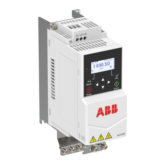
ABB ACS180 Hardware Manual
Hide thumbs
Also See for ACS180:
- Firmware manual (392 pages) ,
- Quick installation and start-up manual (2 pages) ,
- Hardware manual (192 pages)
Table of Contents
Advertisement
Quick Links
Advertisement
Table of Contents

Related Manuals for ABB ACS180


Summary of Contents for ABB ACS180
- Page 1 — ABB MACHINERY DRIVES ACS180 drives Hardware manual...
- Page 3 ACS180 drives Hardware manual Table of contents 1. Safety instructions 4. Mechanical installation 6. Electrical installation 3AXD50000467945 Rev B Original instructions EFFECTIVE: 2022-06-28...
-
Page 5: Table Of Contents
Contents of this chapter ..................Operation principle ....................Simplified main circuit diagram ..............Product variants ....................... Layout ......................... Frame sizes R0...R1 .................... Frame sizes R2...R4 ................... Control connections ....................Standard variant (ACS180-04S-...) ..............Base variant (ACS180-04N-...) ................. Control panel options .................... - Page 6 6 Table of contents Drive labels ......................... Model information label ................... Type designation label ..................Type designation key ....................Control panel ......................Home view ......................Status icon ..................... Message view ..................... Options view ...................... Menu ........................4 Mechanical installation Contents of this chapter ..................Installation alternatives ..................
- Page 7 Guidelines for installing the drive to a TT system ........Identifying the grounding system of the electrical power network ..Connecting the power cables ................Connection diagram ..................Connection procedure ..................Connecting the control cables ................Default I/O connection diagram (ABB standard macro) ......
- Page 8 8 Table of contents Control cable connection procedure ............. Additional information on the control connections .......... Connecting EIA-485 fieldbus cable to the drive .......... PNP configuration for digital inputs ............. NPN configuration for digital inputs ............Connection examples of two-wire and three-wire sensors ..... Safe torque off ....................
- Page 9 Table of contents 9 Alternate short-circuit protection ................. Miniature circuit breakers (IEC) ..............Manual self-protected combination motor controller – Type E USA (UL (NEC)) ......................Dimensions and weights ..................Free space requirements ..................Losses, cooling data and noise ................Terminal data for the power cables ..............Typical power cable sizes ..................
- Page 10 Compliance with the European Machinery Directive and the UK Supply of Machinery (Safety) Regulations ..............Wiring .......................... Connection principle ..................Single ACS180 drive, internal power supply ........Single ACS180 drive, external power supply ........Wiring examples ....................Single ACS180 drive, internal power supply ........
- Page 11 Table of contents 11 Validation test procedure ................Use ..........................Maintenance ......................Competence ....................... Fault tracing ......................Safety data ......................... Terms and abbreviations ................. TÜV certificate ....................Declarations of conformity ................Further information...
-
Page 13: Safety Instructions
Safety instructions 13 Safety instructions Contents of this chapter This chapter contains the safety instructions which you must obey when you install, start-up, operate and do maintenance work on the drive. If you ignore the safety instructions, injury, death or damage can occur. Use of warnings and notes Warnings tell you about conditions which can cause injury or death, or damage to the equipment. -
Page 14: General Safety In Installation, Start-Up And Maintenance
14 Safety instructions General safety in installation, start-up and maintenance These instructions are for all personnel who do work on the drive. WARNING! Obey these instructions. If you ignore them, injury or death, or damage to the equipment can occur. •... - Page 15 Safety instructions 15 Note: • If you select an external source for the start command and it is on, the drive will start immediately after fault reset unless you configure the drive for pulse start. See the firmware manual. • If the drive is in remote control mode, you cannot stop or start the drive with the control panel.
-
Page 16: Electrical Safety In Installation, Start-Up And Maintenance
16 Safety instructions Electrical safety in installation, start-up and maintenance ■ Electrical safety precautions These electrical safety precautions are for all personnel who do work on the drive, motor cable or motor. WARNING! Obey these instructions. If you ignore them, injury or death, or damage to the equipment can occur. -
Page 17: Additional Instructions And Notes
Safety instructions 17 ■ Additional instructions and notes WARNING! Obey these instructions. If you ignore them, injury or death, or damage to the equipment can occur. If you are not a qualified electrical professional, do not do installation or maintenance work. •... -
Page 18: Grounding
18 Safety instructions ■ Grounding These instructions are for all personnel who are responsible for the grounding of the drive. WARNING! Obey these instructions. If you ignore them, injury or death, or equipment malfunction can occur, and electromagnetic interference can increase. If you are not a qualified electrical professional, do not do grounding work. -
Page 19: General Safety In Operation
Safety instructions 19 General safety in operation These instructions are for all personnel that operate the drive. WARNING! Obey these instructions. If you ignore them, injury or death, or damage to the equipment can occur. • If you have a cardiac pacemaker or other electronic medical device, keep away from the area near motor, drive, and the drive power cabling when the drive is in operation. -
Page 20: Safety In Operation
20 Safety instructions • Do not do work on the drive when a rotating permanent magnet motor is connected to it. A rotating permanent magnet motor energizes the drive including its input and output power terminals. Before installation, start-up and maintenance work on the drive: •... -
Page 21: Introduction To The Manual
The chapter contains a list of related manuals and a flowchart for installation and commissioning. Applicability This manual is applicable to ACS180 drives. Target audience The reader is expected to know the fundamentals of electricity, wiring, electrical components and electrical schematic symbols. - Page 22 (page 65) Connect the control cables. Connecting the control cables (page 68) Examine the installation. Installation checklist (page 77) Refer to the ACS180 Quick installa- Commission the drive. tion and start-up guide (3AXD50000510344 [English]) and the ACS180 Firmware manual (3AXD50000467860 [English]).
-
Page 23: Terms And Abbreviations
Introduction to the manual 23 Terms and abbreviations Term Description ACS-AP-… Assistant control panel BCBL-01 Optional USB to RJ45 cable Capacitor bank The capacitors connected to the DC link Control unit The part in which the control program runs. DC link DC circuit between rectifier and inverter DC link capacitors Energy storage which stabilizes the intermediate circuit DC voltage... -
Page 24: Related Manuals
24 Introduction to the manual Related manuals Name Code Drive manuals and guides ACS180 drives hardware manual 3AXD50000467945 ACS180 quick installation and start-up guide 3AXD50000510344 ACS180 firmware manual 3AXD50000467860 ACS180 recycling instructions 3AXD50000613342 Option manuals and guides ACS-AP-I, -S, -W and ACH-AP-H, -W Assistant control panel user’s... -
Page 25: Operation Principle And Hardware Description
Operation principle and hardware description 25 Operation principle and hardware description Contents of this chapter This chapter describes the operation principle, layout, type designation label and type designation information. It shows a general diagram of the power connections and control interfaces. -
Page 26: Operation Principle
26 Operation principle and hardware description Operation principle The ACS180 is a drive for controlling asynchronous AC induction motors and permanent magnet synchronous motors. It is optimized for cabinet mounting. ■ Simplified main circuit diagram The figure shows the simplified main circuit diagram of the drive. -
Page 27: Layout
Control panel, display and status LED PE connection (motor) Motor connection terminal Fixed control terminals Cooling fan Front cover Panel and PC tool port (RJ45) Model information label Type designation label 1) Drive types ACS180-04N-xxxx-x do not have this EMC screw. -
Page 28: Frame Sizes R2
PE connection (motor) Motor connection terminal Fixed control terminals Cooling fan Front cover Panel and PC tool port (RJ45) Model information label Type designation label Cold configuration connection for CCA-01 1) Drive types ACS180-04N-xxxx-x do not have this EMC screw. -
Page 29: Control Connections
Operation principle and hardware description 29 Control connections ■ Standard variant (ACS180-04S-...) Connections: 1. Safe torque-off connections 2. Relay output connection 3. Modbus termination jumper 4. Communication mode jumper 5. Digital inputs and outputs 6. Analog inputs and outputs 7. EIA-485 Modbus RTU 8. -
Page 30: Base Variant (Acs180-04N
30 Operation principle and hardware description ■ Base variant (ACS180-04N-...) Connections: 1. Relay output connection 2. Modbus termination jumper 3. Communication mode jumper 4. Digital inputs and outputs 5. Analog inputs and outputs 6. EIA-485 Modbus RTU 7. Panel connector (external panel or adapter for PC connection) 8. -
Page 31: Control Panel Options
Operation principle and hardware description 31 Control panel options The drive supports these control panels: • integrated control panel • ACS-AP-I assistant control panel • ACS-AP-S assistant control panel • ACS-AP-W assistant control panel with Bluetooth • ACS-BP-S basic control panel For information on the assistant control panels, refer to the ACS-AP-I, -S, -W and ACH-AP-H, -W Assistant control panels user’s manual (3AUA0000085685 [EN]). -
Page 32: Type Designation Label
XXXX: Running item number that starts each week from 0001. Type designation key The type designation shows the specifications and configuration of the drive. The table below presents the type code digits. Sample type code 1: ACS180-04N-02A6-4 Sample type code 2: ACS180-04S-02A6-4 Code Description... -
Page 33: Control Panel
By default, ACS 180 has an integrated panel. If required, you can panels such as assistant control panel or a basic panel. For more For quick reference, there is an ACS180 User interface guide (3AXD50000606696 ACX-AP-x assistant control panel’s user’s manual (3AUA000008 [multi lingual]). -
Page 34: Home View
34 Operation principle and hardware description • Push the OK key to open the highlighted setting or item. • Use the left and right arrow keys to highlight a value. • Use the up and down arrow keys to set a value. •... -
Page 35: Message View
Operation principle and hardware description 35 ■ Message view For fault and warning information, refer to the ACS180 Firmware manual (3AXD50000467860 [English]). To reset a fault, push the OK key (with the soft-key label Reset? ). ■ Options view To open the Options view, push the Back key in the Home view. -
Page 37: Mechanical Installation
Mechanical installation 37 Mechanical installation Contents of this chapter The chapter tells you how to examine the installation site, unpack, check the delivery and install the drive mechanically. Installation alternatives You can install the drive onto an assembly plate with screws. Installation requirements: •... -
Page 38: Examining The Installation Site
38 Mechanical installation • Make sure that the hot cooling air from a drive does not go into the cooling air inlet of other equipment. • Install the drive inside a cabinet or enclosure. The drive has an IP20 (UL Open Type) ingress protection classification for cabinet installation. - Page 39 Mechanical installation 39 Package contents: drive 2. installation accessories (cable clamps, metal grounding plate, screws, etc.) 3. quick installation and start-up guide.
-
Page 40: Installing The Drive
40 Mechanical installation Installing the drive You can install the drive: • With screws to a suitable surface (wall or assembly plate). • To a DIN installation rail with the integrated lock for frame sizes R3 and R4. ■ To install the drive with screws Make marks onto the surface for the mounting holes. - Page 41 Mechanical installation 41 4. Tighten the mounting screws.
-
Page 42: To Install The Drive To A Din Installation Rail For Frame Sizes R3 And R4
42 Mechanical installation ■ To install the drive to a DIN installation rail for frame sizes R3 and R4 Use an IEC/EN 60715 top hat type installation rail, width × height = 35 × 7.5 mm (1.4 × 0.3 in). Move the locking part to the left. -
Page 43: Guidelines For Planning The Electrical Installation
ABB does not assume any liability whatsoever for any installation which breaches the local laws and/or other regulations. Furthermore, if the recommendations given by ABB are not followed, the drive may experience problems that the warranty does not cover. -
Page 44: European Union And United Kingdom
44 Guidelines for planning the electrical installation ■ European Union and United Kingdom To comply with European Union directives and United Kingdom regulations related to standard EN 60204-1, the disconnecting device must be one of these types: • switch-disconnector of utilization category AC-23B (IEC 60947-3) •... -
Page 45: Selecting The Power Cables
Guidelines for planning the electrical installation 45 Selecting the power cables ■ General guidelines Select the input power and motor cables according to local regulations. • Current: Select a cable capable of carrying the maximum load current and suitable for the prospective short-circuit current provided by the supply network. -
Page 46: Alternate Power Cable Types
46 Guidelines for planning the electrical installation Cable type Use as input power cabling Use as motor cabling and as brake resistor cabling Symmetrical shielded (or ar- mored) cable with three phase conductors and sym- metrically constructed PE conductor and a shield (or armor) Symmetrical shielded (or ar- mored) cable with three... -
Page 47: Not Allowed Power Cable Types
Symmetrical shielded cable with individual shields for each phase conductor ■ Additional guidelines, North America ABB recommends the use of metallic conduit for power wiring. ABB also recommends the use of symmetrical shielded VFD cable between drive and motor(s). -
Page 48: Metal Conduit
48 Guidelines for planning the electrical installation This table shows examples of methods for wiring the drive. Refer to NEC 70 along with state and local codes for the appropriate methods for your application. Wiring method Notes 1) 2) Conduit - Metallic Electrical metallic tubing: Type EMT Prefer symmetrical shielded VFD cable. -
Page 49: Selecting The Control Cables
Guidelines for planning the electrical installation 49 requirement of the motor cable shield of the drive is shown below. It consists of a concentric layer of copper wires with an open helix of copper tape or copper wire. The better and tighter the shield, the lower the emission level and bearing currents. -
Page 50: Signals That Can Be Run In The Same Cable
50 Guidelines for planning the electrical installation ■ Signals that can be run in the same cable If their voltage does not exceed 48 V, relay-controlled signals can be run in the same cables as digital input signals. The relay-controlled signals should be run as twisted pairs. -
Page 51: General Guidelines - North America
Guidelines for planning the electrical installation 51 min. 300 mm (12 in) min. 300 mm (12 in) min. 500 mm (20 in) 90° min. 200 mm (8 in) min. 500 mm (20 in) Motor cable Input power cable Control cable Brake resistor or chopper cable (if any) ■... -
Page 52: Continuous Motor Cable Shield/Conduit Or Enclosure For Equipment On The Motor Cable
52 Guidelines for planning the electrical installation Input power cabling Motor cabling Conduit ■ Continuous motor cable shield/conduit or enclosure for equipment on the motor cable To minimize the emission level when safety switches, contactors, connection boxes or similar equipment are installed on the motor cable between the drive and the motor: •... -
Page 53: Separate Control Cable Ducts
Guidelines for planning the electrical installation 53 ■ Separate control cable ducts Put 24 V DC and 230 V AC (120 V AC) control cables in separate ducts, unless the 24 V DC cable is insulated for 230 V AC (120 V AC) or insulated with an insulation sleeving for 230 V AC (120 V AC). -
Page 54: Protecting The Drive, And The Input Power And Motor Cables Against Thermal Overload
54 Guidelines for planning the electrical installation ■ Protecting the drive, and the input power and motor cables against thermal overload If the cables have the correct size for the nominal current, the drive protects itself and the input and motor cables against thermal overload. No additional thermal protection devices are needed. -
Page 55: Implementing Motor Temperature Sensor Connection
Guidelines for planning the electrical installation 55 Implementing motor temperature sensor connection WARNING! IEC 61800-5-1 requires double or reinforced insulation between live parts and accessible parts when: • the accessible parts are not conductive, or • the accessible parts are conductive, but not connected to the protective earth. -
Page 56: Implementing The Emergency Stop Function
143). Using a safety switch between the drive and the motor ABB recommends to install a safety switch between the permanent magnet motor and the drive output. The switch is needed to isolate the motor from the drive during maintenance work on the drive. -
Page 57: Protecting The Contacts Of Relay Outputs
Guidelines for planning the electrical installation 57 When you select the vector motor control mode and the motor coast stop mode, you can open the contactor immediately after the drive has received the stop command. This is the case also if you use the scalar motor control mode. Protecting the contacts of relay outputs Inductive loads (relays, contactors, motors) cause voltage transients when switched off. -
Page 59: Electrical Installation
Electrical installation 59 Electrical installation Contents of this chapter This chapter describes how to: • measure the insulation • do an earthing system compatibility check • change the EMC filter connection • connect the power and control cables • install optional modules •... -
Page 60: Measuring The Insulation
Use a measuring voltage of 1000 V DC. The insulation resistance of an ABB motor must be more than 100 Mohm (reference value at 25 °C [77 °F]). For the insulation resistance of other motors, refer to... -
Page 61: Earthing System Compatibility Check
Earthing system compatibility check ■ EMC filter The drive ACS180-04S-...-1/4 has an internal EMC filter as standard. You can install the drive to a symmetrically grounded TN-S system. If you install the drive to another system, you must disconnect the EMC filter. -
Page 62: Disconnecting The Emc Filter
Do not remove Do not remove 1) Can install the metal screw included in the drive delivery to connect the internal EMC filter. Note: ACS180-04N-...-4 drives do not support corner-grounded delta (B1) system. ■ Disconnecting the EMC filter Do the steps in section... -
Page 63: Guidelines For Installing The Drive To A Tt System
Note: • ABB does not guarantee the EMC performance, because the internal EMC filter is disconnected. • ABB does not guarantee the functioning of the ground leakage detector built inside the drive. - Page 64 64 Electrical installation To identify the grounding system, examine the supply transformer connection. See the applicable electrical diagrams of the building. If that is not possible, measure these voltages at the distribution board, and use the table to define the grounding system type.
-
Page 65: Connecting The Power Cables
PE conductor. Motor cable Note: ABB recommends to use a symmetrical shielded cable (VFD cable) as the motor cable. Separate PE cable (motor side). Use a separate grounding cable for the motor side, if the conductivity of the shield is not sufficient, or if there is no symmetrically constructed PE conductor in the cable. -
Page 66: Connection Procedure
66 Electrical installation ■ Connection procedure WARNING! Obey the safety instructions of the drive. If you ignore them, injury or death, or damage to the equipment can occur. If you are not a qualified electrical professional, do not do installation, commissioning or maintenance work. - Page 67 Electrical installation 67 M4x10, 2x 3. Strip the motor cable. 4. Ground the motor cable shield under the grounding clamp. 5. Twist the motor cable shield into a bundle, mark it with yellow-green and connect it to the grounding terminal. 6.
-
Page 68: Connecting The Control Cables
12. Mechanically attach the cables on the outside of the drive. Connecting the control cables Refer to Default I/O connection diagram (ABB standard macro) for the default I/O connections of the ABB standard macro. For other macros, refer to the ACS180 firmware manual (3AXD50000467860 [English]). -
Page 69: Default I/O Connection Diagram (Abb Standard Macro)
Electrical installation 69 ■ Default I/O connection diagram (ABB standard macro) Description Connection Term. Digital I/O 24 V Aux. +24 V DC, max 200 mA DGND Aux. voltage output common Stop (0) / Start (1) Forward (0) / Reverse (1) -
Page 70: Control Cable Connection Procedure
70 Electrical installation ■ Control cable connection procedure Do the connections according to the macro in use. Keep the signal wire pairs twisted as near to the terminals as possible to prevent inductive coupling. WARNING! Obey the safety instructions of the drive. If you ignore them, injury or death, or damage to the equipment can occur. - Page 71 Electrical installation 71 R3: M3x12, 2x R4: M4x8, 2x R3/R4 4. Strip a part of the outer shield of the control cable for 360-degree grounding. 5. Use a 360-degree grounding clamp to connect the cable to the grounding tab. 6. Strip the ends of the control cable conductors. For stranded (multi-wire) conductors, install ferrules at the bare conductor ends.
-
Page 72: Additional Information On The Control Connections
72 Electrical installation Additional information on the control connections ■ Connecting EIA-485 fieldbus cable to the drive Connect the fieldbus to the EIA-485 Modbus RTU terminal on the front of the drive. The EIA-485 network uses shielded, twisted-pair cable for data signaling with characteristic impedance between 100 and 130 ohm. -
Page 73: Pnp Configuration For Digital Inputs
Electrical installation 73 ■ PNP configuration for digital inputs Internal and external +24 V power supply connections for PNP (source) configuration are shown in the figure below. Internal +24 V power supply External +24 V power supply +24 V +24 V 0 V DC DGND DGND... -
Page 74: Connection Examples Of Two-Wire And Three-Wire Sensors
74 Electrical installation ■ Connection examples of two-wire and three-wire sensors The figures give examples of connections for a two-wire or three-wire sensor/transmitter that is supplied by the auxiliary voltage output of the drive. 4…20 mA AGND +24V DGND Process actual value measurement or reference, 4 … 20 mA, R in = 205 ohm. Note: The sensor power supply comes through its current output circuit, use AGND 4 …... -
Page 75: Connecting A Pc
A – type Mini-B cable. The maximum permitted length of the cable is 3 m (9.8 ft). • Use a USB to RJ45 converter. You can order it from ABB (BCBL-01, 3AXD50000032449). Connect the cable to the Panel and PC tool port (RJ45). -
Page 77: Installation Checklist
Installation checklist 77 Installation checklist Contents of this chapter This chapter contains a checklist for the mechanical and electrical installation of the drive. Checklist Examine the mechanical and electrical installation of the drive before start-up. Go through the checklist together with another person. WARNING! Obey the safety instructions of the drive. - Page 78 78 Installation checklist Make sure that … The insulation resistance of the input power cable, motor cable and motor is meas- ured according to local regulations and the manuals of the drive. The drive is attached securely on an even, vertical and non-flammable wall. The cooling air flows freely in and out of the drive.
-
Page 79: Maintenance
Maintenance intervals The tables below show the maintenance tasks which can be done by the end user. The complete maintenance schedule is available on the Internet (https://new.abb.com/drives/services/maintenance/preventive-maintenance). For more information, consult your local ABB Service representative (www.abb.com/searchchannels). ■ Description of symbols... -
Page 80: Recommended Maintenance Intervals After Start-Up
• Maintenance and component replacement intervals are based on the assumption that the equipment is operated within the specified ratings and ambient conditions. ABB recommends annual drive inspections to ensure the highest reliability and optimum performance. • Long term operation near the specified maximum ratings or ambient conditions may require shorter maintenance intervals for certain components. -
Page 81: Replacing The Cooling Fans
Parameter 05.04 Fan on-time counter shows the running time of the cooling fan. After you replace the fan, reset the fan counter. Refer to the firmware manual. You can get replacement fans from ABB. Use only ABB specified spare parts. ■... - Page 82 82 Maintenance 3. Carefully lift the fan cover out of the drive. Note that the fan cover holds the cooling fan. 4. Disconnect the fan power cable. 5. Free the fan clips and remove the fan from the fan cover. 6.
-
Page 83: To Replace The Cooling Fan For Frame Size R2
Maintenance 83 7. Connect the fan power cable. 8. Carefully put the fan cover into position in the drive. Make sure that the fan power cable is routed correctly. Push the cover to lock into position. ■ To replace the cooling fan for frame size R2 WARNING! Obey the safety instructions of the drive. - Page 84 84 Maintenance Stop the drive and do the steps in section Electrical safety precautions (page 16) before you start the work. 2. Press the two clips by fingers to open the fan cover. 3. Carefully lift the fan cover out of the drive. Note that the fan cover holds the cooling fan.
-
Page 85: To Replace The Cooling Fan For Frame Size R3
Maintenance 85 Place cables into the slot. Keep cables on the right of the side plate. 7. Connect the fan power cable. 8. Carefully put the fan cover into position in the drive. Make sure that the fan power cable is routed correctly. Push the cover to lock into position. ■... - Page 86 86 Maintenance 3. Carefully lift the fan cover out of the drive. The fan cover holds the cooling fan. 4. Disconnect the fan power cable.
- Page 87 Maintenance 87 5. Install the new fan into the fan cover. Make sure that the air flow is in the correct direction. The air flows in from the bottom of the drive and out from the top of the drive. 6.
-
Page 88: To Replace The Cooling Fan For Frame Size R4
88 Maintenance ■ To replace the cooling fan for frame size R4 WARNING! Obey the safety instructions of the drive. If you ignore them, injury or death, or damage to the equipment can occur. If you are not a qualified electrical professional, do not do installation, commissioning or maintenance work. -
Page 89: Capacitors
Capacitor life can be extended by decreasing the surrounding air temperature. Capacitor failure is usually followed by damage to the unit and an input cable fuse failure, or a fault trip. If you think that any capacitors in the drive have failed, contact ABB. ■ Reforming the capacitors The capacitors must be reformed if the drive has not been powered (either in storage or unused) for a year or more. -
Page 91: Technical Data
IEC ratings Output ratings Input Input cur- with Max. Light-duty Heavy-duty Nominal use rent choke current ACS180-04... Frame I max I Ld P Ld I Hd P Hd size 1-phase U n = 200 ... 240 V -02A4-1 0.37 0.37 0.25 -03A7-1 0.55... -
Page 92: Ul (Nec) Ratings
92 Technical data Output ratings Input Input cur- with Max. Light-duty Heavy-duty Nominal use rent choke current ACS180-04... Frame I max I Ld P Ld I Hd P Hd size -04A8-2 0.75 0.75 0.55 -06A9-2 10.4 0.75 -07A8-2 11.7 11.9 -09A8-2 14.7... - Page 93 Technical data 93 ACS180-04... Input Input Output ratings cur- with Max. Light-duty use Heavy-duty use Frame rent choke current size I max I Ld P Ld I Hd P Hd -04A8-1 0.75 -06A9-1 12.6 -07A8-1 17.3 11.9 -09A8-1 21.8 13.3 -12A2-1 23.9...
-
Page 94: Definitions
Typical motor power in heavy-duty use (150% overload) ■ Sizing ABB recommends the DriveSize tool for selecting the drive, motor and gear combination (https://new.abb.com/drives/software-tools/drivesize). You can also use the ratings tables. The minimum recommended nominal current of the motor is 40% of the drive nominal output current ( I ) . - Page 95 Example 1, IEC: How to calculate the derated current The drive type is ACS180-04x-17A0-4, which has a nominal output current ( I ) of 17 A at 400 V. Calculate the derated output current at 4 kHz switching frequency, at 1500 m altitude and at 55 °C surrounding air temperature.
- Page 96 ( I ) by all the applicable derating factors. For example, drive type ACS180-04x-12A6-4 has a nominal output current of 12.6 A at 400 V. The switching frequency derating factor for this drive type is 0.68 at 8 kHz.
-
Page 97: Surrounding Air Temperature Derating
Technical data 97 ■ Surrounding air temperature derating Frame Installation with 50mm space Install side-by-side between Derating factor for 100% 100% I Hd (Heavy duty rating, 150% overloadabil- ity) (°C) (°C) (°F) (°F) Ambient temperature Ambient temperature Derating factor for 100% 100% I N and I Ld... - Page 98 Derating factor for 100% I Hd (°C) (°F) Ambient temperature Derating factor for 100% I N and I Ld on ACS180-...-1/2 (°C) (°F) Ambient temperature Derating factor for 100% I N and I Ld on ACS180-...-4 (°C) (°F) Ambient temperature...
-
Page 99: Altitude Derating
Technical data 99 Frame Installation with 50mm space Install side-by-side between Derating factor for 100% I N, I Ld and I Hd on ACS180-04x- 048A-2, 045A-4 (°C) (°F) Ambient temperature Derating factor for 100% I N, I Ld and I Hd on... - Page 100 100 Technical data Type Current multiplier with different switching frequencies ACS180-04... 2 kHz 4 kHz 8 kHz 12 kHz -03A7-2 -04A8-2 -06A9-2 -07A8-2 -09A8-2 -15A6-2 -17A5-2 -25A0-2 -033A-2 -048A-2 -055A-2 3-phase U n = 380 ... 480 V -01A8-4 -02A6-4...
-
Page 101: Fuses
Make sure that the operating time of the fuse is less than 0.5 seconds. Obey the local regulations. Min. short- Input Nominal Voltage I 2 t circuit cur- current current rating ACS180-04... ABB type rent A 2 s 1-phase U n = 200 ... 240 V -02A4-1 C10G10 -03A7-1 C10G16 -04A8-1 C10G16 -06A9-1 12.6... -
Page 102: Gr Or Ar -Type Fuses (Iec)
102 Technical data Min. short- Input Nominal Voltage I 2 t circuit cur- current current rating ACS180-04... ABB type rent A 2 s -03A3-4 C10G10 -04A0-4 C10G10 -05A6-4 C10G16 -07A2-4 1200 C10G20 -09A4-4 2300 C10G25 -12A6-4 17.4 3000 C10G32 -17A0-4 25.2... -
Page 103: Ul Fuses (Ul(Nec))
Technical data 103 Min. short- Input Nominal Voltage I 2 t circuit cur- current current rating ACS180-04... Bussmann type rent A 2 s -048A-2 11700 FWP-150A -055A-2 11700 FWP-150A 3-phase U n = 380 ... 415 V -01A8-4 FWP-20G14F -02A6-4... -
Page 104: Alternate Short-Circuit Protection
The protective characteristics of the circuit breakers depend on the type, construction and settings of the breakers. There are also limitations pertaining to the short-circuit capacity of the supply network. Your local ABB representative can help you in selecting the breaker type when the supply network characteristics are known. - Page 105 You can use the circuit breakers listed below. You can also use other circuit breakers with the drive if they provide the same electrical characteristics. ABB does not assume any liability whatsoever for the correct function and protection with circuit breakers not listed below.
-
Page 106: Manual Self-Protected Combination Motor Controller - Type E Usa (Ul (Nec))
Manual self-protected combination motor controller – Type E USA (UL (NEC)) You can use the ABB Type E manual motor protectors (MMP) MS132 & S1-M3-25, MS165-xx and MS5100-100 as an alternative to the recommended fuses as a means of branch circuit protection. This is in accordance with the National Electrical Code (NEC). - Page 107 4) For all drives, the enclosure must be sized to accommodate the specific thermal considerations of the application as well as provide free space for cooling. Refer to the technical data. For UL only: The minimum enclosure volume is specified in the UL listing when applied with the ABB Type E MMP shown in the table.
-
Page 108: Dimensions And Weights
108 Technical data Dimensions and weights Frame Weight size 6.85 8.23 5.35 2.76 5.63 2.36 6.46 0.92 2.03 7.48 8.66 5.98 2.76 5.63 2.36 7.09 1.24 2.73 7.95 9.06 164.5 6.48 4.72 5.63 4.17 190.5 1.92 4.23 8.07 164.5 6.48 6.69 6.85 5.83... -
Page 109: Free Space Requirements
Note: power losses are given for nominal supply voltage, default switching frequency, and rated output current/power. Changing these factors may result in increased power losses. Air flow Noise Typical power loss Frame ACS180-04... size m 3 /h BTU/h dB(A) 1-phase U n = 200 ... 240 V -02A4-1... -
Page 110: Terminal Data For The Power Cables
110 Technical data Air flow Noise Typical power loss Frame ACS180-04... size m 3 /h BTU/h dB(A) 3-phase U n = 380 ... 480 V -01A8-4 -02A6-4 -03A3-4 -04A0-4 36.29 21.36 50.9 -05A6-4 36.29 21.36 50.9 -07A2-4 36.29 21.36 50.9 -09A4-4 36.29... - Page 111 Technical data 111 ACS180- L1, L2, L3, T1/U, T2/V, T3/W, R-, R+/ 04... UDC+ Minimum Maximum Tightening Minimum Maximum Tightening (sol- (sol- torque (sol- (sol- torque id/stran- id/stran- id/stran- id/stran- ded) ded) ded) ded) mm 2 mm 2 mm 2 mm 2 N·m...
- Page 112 112 Technical data ACS180- L1, L2, L3, T1/U, T2/V, T3/W, R-, R+/ 04... UDC+ Minimum Maximum Tightening Minimum Maximum Tightening torque torque lbf·in lbf·in -04A8-1 10.6 -06A9-1 10.6 -07A8-1 10.6 -09A8-1 10.6 -12A2-1 10.6 3-phase U n = 200 ... 240 V -02A4-2 10.6...
-
Page 113: Typical Power Cable Sizes
The terminals do not accept a conductor that is one size larger than the maximum specified wire size. • The maximum number of conductors per terminal is 1. Typical power cable sizes Cable conductor sizes (mm 2 ) ACS180-04... Frame 1-phase U n = 200 ... 240 V -02A4-1 3×1.5 + 1.5 -03A7-1 3×1.5 + 1.5... -
Page 114: Terminal Data For The Control Cables
The table shows the external EMC filters. See also EMC compatibility and motor cable length Technical data (page 91). ACS180- EMC filter type 04... ABB order code Schaffner order code 1-phase U n = 200 ... 240 V 02A4-1 RFI-12 FS 21754-16.1-07 03A7-1 RFI-12 FS 21754-16.1-07... -
Page 115: Electrical Power Network Specification
Electrical power network specification Voltage (U1) ACS180-04x-xxxx-1 drives: 1-phase 200 … 240 V AC -15% ... +10% ACS180-04x-xxxx-2 drives: 3-phase 200 … 240 V AC -15% ... +10% ACS180-04x-xxxx-4 drives: 3-phase 380 … 480 V AC -15% ... +10% Network type Public low-voltage networks. -
Page 116: Motor Connection Data
Mains choke Use a mains choke if the network's line impedance is low (less than 0.3% total system impedance of all the ACS180 drives in the install- ation), or has voltage imbalance, or harmonic distortion that make the input current bigger than the nominal input current ratings. You can use one choke for several drives as long as the choke current rating is not exceeded. - Page 117 Technical data 117 Frame Maximum motor cable length With external output chokes Note: In multimotor systems, the calculated sum of all motor cable lengths must not exceed the maximum motor cable length given in the table.
-
Page 118: Emc Compatibility And Motor Cable Length
118 Technical data EMC compatibility and motor cable length To comply with the EMC limits in the European EMC Directive (standard IEC/EN 61800-3), use these maximum motor cable lengths for the 4 kHz switching frequency. Frame Maximum motor cable length, 4 kHz Class 2 Class 3 Class 1... -
Page 119: Control Connection Data
For ACS180-04N... drives, the maximum motor cable lengths are according to the motor cable length table. The EMC category for these drives is C4. • For ACS180-04S-...-2 drives, the EMC category is C4. In order to achieve higher EMC category, must use external EMC filters. Control connection data... -
Page 120: Brake Resistor Connection Data
Energy efficiency data (ecodesign) Energy efficiency data according to IEC 61800-9-2 is available from the ecodesign tool (https://ecodesign.drivesmotors.abb.com/). Energy efficiency data is not provided for the 1~230 V drives. The drives with one phase input are not in the scope of the EU ecodesign requirements (Regulation EU/2019/1781) or the UK ecodesign requirements (Regulation SI 2021 No. - Page 121 Technical data 121 Requirement Operation installed for sta- Storage in the Transportation in tionary use protective pack- the protective package Installation site alti- 0 … 1000 m above sea level tude without derating. 1000 … 2000 m above sea level with derating. Surrounding air tem- For frame size R0: -40 …...
-
Page 122: Materials
IEC 62635 guidelines. To aid recycling, plastic parts are marked with an appropriate identification code. Contact your local ABB distributor for further information on environmental aspects and recycling instructions for professional recyclers. End of life treatment must follow international and local regulations. -
Page 123: Markings
Product is compliant with the People’s Republic of China Electronic Industry Standard (SJ/T 11364-2014) about hazardous substances. The EFUP is 20 years. China RoHS II Declaration of Conformity is available from https://library.abb.com. WEEE mark At the end of life the product should enter the recycling system at an appropriate collection point and not placed in the normal waste stream. -
Page 124: Compliance With En 61800-3
■ Category C1 This is applicable to ACS180-04S-...-1/-4 drives with an external EMC C1 filter. The drive complies with the conducted emission limits of the standard with the following provisions: The optional EMC filter is selected according to section... -
Page 125: Category C2
Technical data 125 ■ Category C2 This is applicable to ACS180-04S-...-1 drives with an internal EMC C2 filter. The drive complies with the standard with the following provisions: The motor and control cables are selected as specified in this manual. - Page 126 Drive 2. An EMC plan for preventing disturbances is drawn up for the installation. A template is available from the local ABB representative. 3. The motor and control cables are selected as specified in this manual. 4. The drive is installed according to the instructions given in this manual.
-
Page 127: Ul Checklist
Technical data 127 UL checklist WARNING! Operation of this drive requires detailed installation and operation instructions provided in the hardware and software manuals. The manuals are provided in electronic format in the drive package or on the Internet. Keep the manuals with the drive at all times. Hard copies of the manuals can be ordered through the manufacturer. -
Page 128: Compliance With The European Machinery Directive
Notwithstanding any other provision to the contrary and regardless of whether the contract is terminated or not, ABB and its affiliates are under no circumstances liable for damages and/or losses related to such security breaches, any unauthorized access, interference, intrusion, leakage and/or theft of data or... -
Page 129: Dimension Drawings
Dimension drawings 129 Dimension drawings Contents of this chapter The chapter contains the dimension drawings of the drive. The dimensions are in millimeters and inches. -
Page 130: Frame R0
130 Dimension drawings Frame R0... -
Page 131: Frame R1
Dimension drawings 131 Frame R1... -
Page 132: Frame R2
132 Dimension drawings Frame R2 [9.055] 19,2 [.756] [.240] [.220] 19,2 [.756] 28,3 [1.114] [7.953] 16,7 [.657] 23,1 [.907] 61,4 [2.415] 190,5 [2.165] [7.500] 13,5 86,8 [.532] [3.415] 80,4 [.256] [3.165] 74,1 [2.915] 67,7 [2.665]... -
Page 133: Frame R3
Dimension drawings 133 Frame R3... -
Page 134: Frame R4
134 Dimension drawings Frame R4... -
Page 135: Resistor Braking
Resistor braking 135 Resistor braking Contents of this chapter The chapter describes how to select the brake resistor and cables, protect the system, connect the brake resistor and enable resistor braking. Safety WARNING! Do not do work on the brake resistor or the resistor cable when the drive is energized. - Page 136 136 Resistor braking 3. Calculate energy E with Equation 2. Rpulse 4. Select the resistor so that the following conditions are met: • The rated power of the resistor must be greater than or equal to P Rmax • Resistance R must be between R and R given in the table for the used drive type.
-
Page 137: Reference Brake Resistors
Do not use a brake resistor with a resistance below the minimum value specified for the particular drive. The drive and the internal chopper are not able to handle the overcurrent caused by the low resistance. ■ Reference brake resistors ACS180- Example resistor R min R max P BRcont... -
Page 138: Selecting And Routing The Brake Resistor Cables
IGBT semiconductors of the brake chopper. Note: ABB has not verified that the EMC requirements are fulfilled with custom brake resistors and cabling. The customer must consider the EMC compliance of the complete installation. -
Page 139: Protecting The System In Brake Circuit Fault Situations
The drive has a brake thermal model which protects the brake resistor against overload. ABB recommends to enable the thermal model at start up. ABB recommends to equip the drive with a main contactor for safety reasons even when you have enabled the resistor thermal model. Wire the contactor so that it opens in case the resistor overheats. -
Page 140: Mechanical And Electrical Installation Of Brake Resistor
140 Resistor braking ABB recommends that you also wire the thermal switch to a digital input of the drive, and configure the input to cause a fault trip at resistor overtemperature indication. Θ +24V Drive input power connection with a main contactor... -
Page 141: Electrical Installation
Resistor braking 141 ■ Electrical installation Measuring the insulation See the electrical installation instructions of the drive. Connecting power cables See the electrical installation instructions of the drive. Connection the control cables Connect the thermal switch of the brake resistor as described in Protecting the system against thermal overload (page 139). -
Page 143: The Safe Torque Off Function
The Safe torque off function 143 The Safe torque off function Contents of this chapter This chapter describes the Safe torque off (STO) function of the drive and gives instructions for its use. Description The Safe torque off function can be used, for example, as the final actuator device of safety circuits (such as an emergency stop circuit) that stop the drive in case of danger. -
Page 144: Compliance With The European Machinery Directive And The Uk Supply Of Machinery (Safety) Regulations
144 The Safe torque off function Standard Name IEC 61000-6-7:2014 Electromagnetic compatibility (EMC) – Part 6-7: Generic standards – Immunity requirements for equipment intended to perform functions in a safety-related system (functional safety) in industrial locations IEC 61326-3-1:2017 Electrical equipment for measurement, control and laborat- ory use –... -
Page 145: Wiring
The Safe torque off function 145 Wiring For the electrical specifications of the STO connection, see the technical data of the control unit. ■ Connection principle Single ACS180 drive, internal power supply + 24 V DC SGND UDC+ UDC- Drive... -
Page 146: Single Acs180 Drive, External Power Supply
146 The Safe torque off function Single ACS180 drive, external power supply 24 V DC + 24 V DC SGND UDC+ UDC- Drive Control unit Control logic To motor Activation switch... -
Page 147: Wiring Examples
The Safe torque off function 147 ■ Wiring examples Single ACS180 drive, internal power supply SGND Drive Safety PLC Safety relay Single ACS180 drive, external power supply 24 V DC SGND Drive Safety PLC Safety relay... -
Page 148: Multiple Acs180 Drives, Internal Power Supply
148 The Safe torque off function Multiple ACS180 drives, internal power supply +24 V SGND SGND SGND Drive Control unit Activation switch... -
Page 149: Multiple Acs180 Drives, External Power Supply
The Safe torque off function 149 Multiple ACS180 drives, external power supply 24 V DC – +24 V SGND SGND SGND Drive Control unit Activation switch ■ Activation switch In the wiring diagrams, the activation switch has the designation [K]. This represents a component such as a manually operated switch, an emergency stop push button switch, or the contacts of a safety relay or safety PLC. -
Page 150: Cable Types And Lengths
The contacts of the switch or relay must open/close within 200 ms of each other. ■ Cable types and lengths • ABB recommends double-shielded twisted-pair cable. • Maximum cable lengths: • 300 m (1000 ft) between activation switch [K] and drive control unit •... -
Page 151: Operation Principle
The Safe torque off function 151 Operation principle The Safe torque off activates (the activation switch is opened, or safety relay contacts open). 2. The STO inputs of the drive control unit de-energize. 3. The control unit cuts off the control voltage from the output IGBTs. 4. -
Page 152: Start-Up Including Validation Test
152 The Safe torque off function Start-up including validation test To ensure the safe operation of a safety function, validation is required. The final assembler of the machine must validate the function by performing a validation test. The test must be performed at initial start-up of the safety function 2. - Page 153 The Safe torque off function 153 Action Test the operation of the STO function when the motor is stopped. • Give a stop command for the drive (if running) and wait until the motor shaft is at a standstill. Make sure that the drive operates as follows: •...
-
Page 154: Use
154 The Safe torque off function Open the activation switch, or activate the safety functionality that is wired to the STO connection. 2. The STO inputs on the drive control unit de-energize, and the control unit cuts off the control voltage from the output IGBTs. 3. - Page 155 The Safe torque off function 155 • The Safe torque off function is ineffective against deliberate sabotage or misuse. • The Safe torque off function has been designed to reduce the recognized hazardous conditions. In spite of this, it is not always possible to eliminate all potential hazards.
-
Page 156: Maintenance
If any wiring or component change is needed after start-up, or the parameters are restored, do the test given in section Validation test procedure (page 152). Use only spare parts approved by ABB. Record all maintenance and proof test activities in the machine logbook. ■ Competence... -
Page 157: Fault Tracing
See the firmware manual of the drive control program for the indications generated by the drive, and for details on directing fault and warning indications to an output on the control unit for external diagnostics. Any failures of the Safe torque off function must be reported to ABB. -
Page 158: Safety Data
158 The Safe torque off function Safety data The safety data for the Safe torque off function is given below. Note: The safety data is calculated for redundant use, and applies only if both STO channels are used. - Page 159 The Safe torque off function 159...
-
Page 160: Terms And Abbreviations
160 The Safe torque off function • The following temperature profile is used in safety value calculations: • 670 on/off cycles per year with Δ T = 71.66 °C • 1340 on/off cycles per year with Δ T = 61.66 °C •... -
Page 161: Tüv Certificate
After the mission time elapses, the safety device must be replaced. Note that any T M values given cannot be regarded as a guarantee or warranty. ■ TÜV certificate The TÜV certificate is available on the Internet at www.abb.com/drives/documents. -
Page 162: Declarations Of Conformity
162 The Safe torque off function ■ Declarations of conformity... - Page 163 The Safe torque off function 163...
- Page 164 164 The Safe torque off function...
- Page 165 The Safe torque off function 165...
- Page 167 Product and service inquiries Address any inquiries about the product to your local ABB representative, quoting the type designation and serial number of the unit in question. A listing of ABB sales, support and service contacts can be found by navigating to www.abb.com/searchchannels.
- Page 168 3AXD50000467945B © Copyright 2022 ABB. All rights reserved. Specifications subject to change without notice.
Need help?
Do you have a question about the ACS180 and is the answer not in the manual?
Questions and answers