Table of Contents
Advertisement
Advertisement
Table of Contents

Related Manuals for Power smart PS5040


Summary of Contents for Power smart PS5040
- Page 1 INSTRUCTION MANUAL 4400W Open Frame Inverter Generator Model # PS5040 Have product questions or need technical support? Please scan the QR code to enter our official website and contact us! Website:www.powersmartusa.com Toll free: 1-800-791-9458 M-F 9-5 EST Website Email: support@amerisuninc.com...
-
Page 3: Table Of Contents
Wiring diagram…………………………………………………………. 22 Exploded view & parts list……………………………………………… 23 Warranty statement……………………………………………………… 28 TECHNICAL DATA 4400W Open Frame Inverter Generator Model # PS5040 Engine type: 4 stroke, OHV, single cylinder with forced air-cooling system Spark plug gap: 0.6-0.8 mm (0.024-0.031 in.) -
Page 4: Introduction
INTRODUCTION Thank You for Purchasing a PowerSmart® Product. This manual provides information regarding the safe operation and maintenance of this product. Every effort has been made to ensure the accuracy of the information in this manual. PowerSmart® reserves the right to change this product and specifications at any time without prior notice. -
Page 5: General Safety Rules
GENERAL SAFETY RULES For any questions regarding the hazard and safety notices listed in this manual or on the product, please call (800) 791-9458 Mon-Fri 9-5 EST before using the generator. Please read and understand the instructions in this manual before starting the engine or attempting to operate this unit. DANGER: CARBON MONOXIDE Using a generator indoors CAN KILL YOU IN MINUTES. -
Page 6: Important Safety Instructions
WARNING: This generator produces heat when running. Temperatures near exhaust can exceed 150℉ (65℃). Do not touch hot surfaces. Pay attention to warning labels on the generator identifying hot parts of the machine. Allow generator to cool down after use before touching engine or areas of the generator that become hot during use. -
Page 7: Symbols
SYMBOLS Some of the following symbols may be used on this product. Please study them and learn their meaning. Proper interpretation of these symbols will allow you to operate the product better and safer. SYMBOL NAME DESIGNATION/EXPLANATION Volts Voltage Amperes Current Hertz Frequency (cycles per second) -
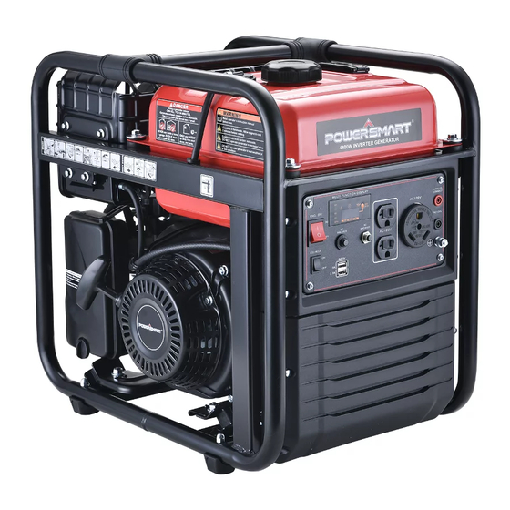
Page 8: Knowing Your Generator
KNOWING YOUR GENERATOR Use the illustrations below to become familiar with the locations and functions of the various components and controls of this generator... - Page 9 Parallel kit terminal It used for parallel operation with another inverter (parallel kit sold separately) Running indicator (green) The running indicator lights up when generating set starts and has normal output. Overload indicator (red) When the overload indicator is on, it indicates that the generating set is overload and it may cause overheat of frequency converter, or increase of AC voltage.
-
Page 10: Generator Preparation
Energy-saving switch When the energy-saving switch is in “ON” position, the energy saving equipment controls the engine rotate speed according to the connected loads. There will be good fuel consumption and low noise. When the energy-saving switch is in“OFF”position, the engine will always run in rated rotate speed no matter it is connected to the loads or not (See the parameter table for details). - Page 11 To add oil, follow these steps: 1. Place the engine on a level surface with engine stopped. 2. Remove the dipstick (See fig.1) and wipe it clean. 3. Reinstall dipstick into tube, rest on oil fill neck, DO NOT thread cap into tube.
- Page 12 NOTICE: Never use engine or carburetor cleaner products in the fuel tank or permanent damage may occur. It is important to prevent gum deposits from forming in essential fuel system parts, such as the carburetor, fuel filter, fuel hose or tank during storage. Also, experience indicates that alcohol-blended fuels (called gasohol, ethanol or methanol) can attract moisture, which leads to separation and formation of acids during storage.
-
Page 13: Starting The Generator
STARTING THE GENERATOR Before starting the generator, make sure you have read and performed the steps in the “Generator Preparation” section of this manual. If you are unsure about how to perform any of the steps in this manual, please call (800) 791-9458 Mon-Fri 9-5 EST or email: support@amerisuninc.com for customer service. - Page 14 STARTING THE ENGINE To start the generator, perform the following steps: 1. Turn the fuel valve to the “ON” position (See fig.4). Fig.4 2. Pull the choke valve switch to “OFF” position (See fig.5). Fig.5 When in cold engine status, turn the choke valve to “ON” position, or turn it to “half -open” position When in hot engine status.
-
Page 15: Using The Generator
WARNING: During the engine warm up, partly open for the choke is necessary until the temperature to a certain level. 5. The generator may be normally loaded. WARNING: Connect the output terminal of the generator with the electric equipment. Do not start or stop the engine when the electric equipment is in “ON”... - Page 16 device(s) with the highest additional surge watts to the total rated watts from step 2. WARNING: You must isolate the generator from electric utility by opening the electrical system’s main circuit breaker or main switch if the generator is used for backup power. Failure to isolate the generator from the power utility may result in injury or death to electric utility workers and damage to the generator due to backfeed of electrical energy.
-
Page 17: Stopping The Generator
STOPPING THE GENERATOR WARNING:Never stop the engine with electrical devices connected and with the connected devices turn “ON”. 1. Remove all the load on generator. 2. Allow the generator run at no load for a few minutes to stabilize internal temperatures of the engine and generator. - Page 18 Proper routine maintenance of the generator will help prolong the life of the machine. Please perform maintenance checks and operations according to the schedule in below chart. NOTE: Note1: Applicable types (if available). Note2: Before each season and after then (whichever comes first). Note3: Service more frequently under severe , dusty, dirty conditions.
- Page 19 ENGINE MAINTENANCE Checking the oil The oil capacity of the engine crankcase is 20.3 fl. oz. 1. Place the engine on a level surface with engine stopped. Check the engine oil level. Remove the oil maintenance cover. Remove the dipstick and wipe it clean. 2.
-
Page 20: Storage & Transport Procedures
SPARK PLUG Spark plug gap : 0.6mm-0.8mm(0.024-0.031 in). Spark plug tighten torque: 15-20N.m The spark plug is important for proper engine operation. A good spark plug should be intact, free of deposits, and properly gapped. Refer to Recommended Maintenance Schedule. To inspect the spark plug: 1. -
Page 21: Troubleshooting
TRANSPORT To prevent fuel spillage when transporting or during temporary storage, the generating set should be secured upright in its normal operating position, with the engine switch OFF. The fuel valve lever should be turned OFF. When transporting: Do not overfill the tank. ... -
Page 22: Wiring Diagram
WIRING DIAGRAM... -
Page 23: Exploded View & Parts List
EXPLODED VIEW & PARTS LIST Generator exploded view... - Page 24 Generator parts list Item Stock# Description Qty. Item Stock# Description Qty. 100011533-0005 Bolt, M6×22 100122169 Muffler 100011539-0001 Bolt, M6×45 100011422-0004 Nut, M8 Inverter 100087975 100006526 Gasket, Muffler Protective Cover 100162760-0001 Control Panel 100079483-0001 Nut, M8 100011265-0003 Bolt, M6×18 1ZZDDF037 Engine 100093717 Inverter 100087976-0002...
- Page 25 Engine exploded view...
- Page 26 Engine parts list Item Stock# Description Qty. Stock# Description Qty. 100011264-0003 Bolt, M6×16 100030062 Motor Base 100056645 Valve Cover 100033258 Guide Clamp 100713739 Breather Hose 100052405 Spring Gasket, Valve 100010181 100005137 Clamp Cover Rocker Arm Fuel Hose 100004419 100017699 Assembly φ4×φ10×320 100050881 Rocker Arm Base...
- Page 27 Item Stock# Description Qty. Item Stock# Description Qty. Gasket, 100010148 100130948 Lower Shield Crankcase Oil Seal, 100010550 Pin,φ8×14 100017644 φ25×φ41.25×6 100010761 Bearing, TM6205 100000655 Clip 100099599 Camshaft 100135644 Stator Assembly 100126476 Crankshaft 100126953 Rotor 100010577 Woodruff Key 100087582 Cooling Fan 100062919 Oil Sensor 100087581...
-
Page 28: Warranty Statement
PowerSmart is committed to building equipment that will provide years of dependable service. Our warranties are consistent with our commitment and dedication to quality. THREE (3) YEARS LIMITED WARRANTY OF POWER SMART PRODUCTS FOR HOME USE. PowerSmart (“Seller") warrants to the original purchaser only, that all PowerSmart consumer power tools will be free from defects in material or workmanship for a period of three (3) years from date of purchase.
Need help?
Do you have a question about the PS5040 and is the answer not in the manual?
Questions and answers