Table of Contents
Advertisement
Quick Links
Please refer to the original service manual for:
CD Mechanism Unit (BRS12C) , Order No. PSG1303059AE
Speaker system SB-AKX220PN, Order No. PSG1601002CE
Speaker system SB-AKX440PN, Order No. PSG1601002CE
TABLE OF CONTENTS
1 Safety Precautions----------------------------------------------- 3
1.1. General Guidelines---------------------------------------- 3
1.2. Before Repair and Adjustment ------------------------- 4
1.3. Protection Circuitry ---------------------------------------- 4
1.4. Power Supply using SMPS Module------------------- 4
1.5. Safety Parts Information --------------------------------- 7
2 Warning -------------------------------------------------------------- 8
to Electrostatically Sensitive (ES) Devices---------- 8
2.2. Precaution of Laser Diode------------------------------- 8
(PbF)---------------------------------------------------------- 9
2.4. Handling Precautions for Traverse Unit-------------- 9
Model No.
Product Color: (K)...Black Type
PAGE
3 Service Navigation --------------------------------------------- 11
3.1. Service Information -------------------------------------- 11
4 Specifications ---------------------------------------------------- 12
5 Location of Controls and Components------------------ 13
5.1. Remote Control Key Button Operation ------------- 13
5.2. Main Unit Key Button Operation---------------------- 14
6 Service Mode ----------------------------------------------------- 16
6.1. Cold-Start -------------------------------------------------- 16
6.2. Sales Demonstration Lock Function ---------------- 16
6.3. Doctor Mode Table--------------------------------------- 17
6.4. Self-Diagnostic Mode ----------------------------------- 19
© Panasonic Corporation 2016. All rights reserved.
Unauthorized copying and distribution is a violation
of law.
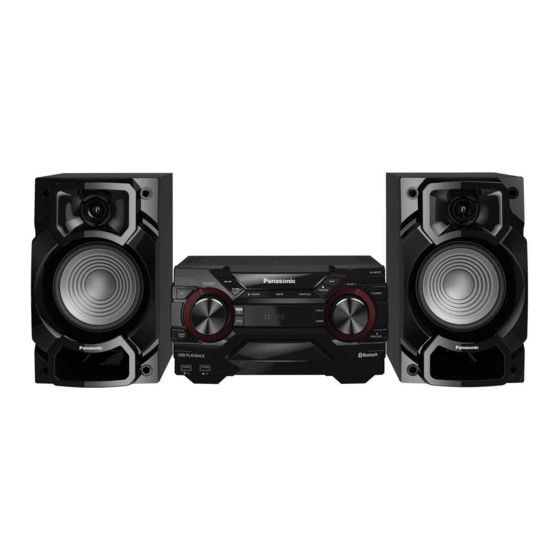
CD Stereo System
SA-AKX220PN
SA-AKX220PS
SA-AKX440PN
SA-AKX440PS
(W)...White Type (For SA-AKX220)
electrostatic
PSG1601001CE
PAGE
breakdown
Advertisement
Table of Contents

Related Manuals for Panasonic SA-AKX220PN


Summary of Contents for Panasonic SA-AKX220PN
-
Page 1: Table Of Contents
6.2. Sales Demonstration Lock Function ---------------- 16 (PbF)---------------------------------------------------------- 9 6.3. Doctor Mode Table--------------------------------------- 17 2.4. Handling Precautions for Traverse Unit-------------- 9 6.4. Self-Diagnostic Mode ----------------------------------- 19 © Panasonic Corporation 2016. All rights reserved. Unauthorized copying and distribution is a violation of law. - Page 2 6.5. Self-Diagnostic Error Code Table -------------------- 19 7 Troubleshooting Guide---------------------------------------- 21 7.1. No Power or No Display -------------------------------- 21 7.2. Bluetooth® Pairing Failure----------------------------- 21 7.3. No Key Function------------------------------------------ 21 7.4. No Remote Control Function -------------------------- 22 7.5. USB Device Cannot Detect---------------------------- 22 7.6.
-
Page 3: Safety Precautions
1 Safety Precautions 1.1. General Guidelines 1. IMPORTANT SAFETY NOTICE There are special components used in this equipment which are important for safety. These parts are marked by in the Schematic Diagrams, Circuit Board Layout, Exploded Views and Replacement Parts List. It is essential that these critical parts should be replaced with manufacturer’s specified parts to prevent X-RADIATION, shock, fire, or other hazards. -
Page 4: Before Repair And Adjustment
Power Supply using SMPS Module This model uses Switching Mode Power Supply (SMPS Module) to provide the power supply to the unit. Here is the supplied part no. for the SMPS Module 1) N0AB1GK00001 (For SA-AKX220PN) 3) N0AD1GK00003 (For SA-AKX220PS) 2) N0AB1GL00001 (For SA-AKX440PN) - Page 5 1.4.1. How to Identify SMPS Figure 1-3 1.4.2. For SA-AKX220PN Figure 1-4 1.4.3. For SA-AKX220PS Figure 1-5...
- Page 6 1.4.4. For SA-AKX440PN Figure 1-6 1.4.5. For SA-AKX440PS Figure 1-7...
-
Page 7: Safety Parts Information
1.5. Safety Parts Information Safety Parts List: There are special components used in this equipment which are important for safety. These parts are marked by in the Schematic Diagrams, Exploded View & Replacement Parts List. It is essential that these critical parts should be replaced with manufacturer’s specified parts to prevent shock, fire or other hazards. -
Page 8: Warning
2 Warning 2.1. Prevention of Electrostatic Discharge (ESD) to Electrostatically Sensi- tive (ES) Devices Some semiconductor (solid state) devices can be damaged easily by static electricity. Such components commonly are called Elec- trostatically Sensitive (ES) Devices. The following techniques should be used to help reduce the incidence of component damage caused by electrostatic discharge (ESD). -
Page 9: General Description About Lead Free Solder (Pbf)
Figure 2-1 2.3. General description about Lead Free Solder (PbF) The lead free solder has been used in the mounting process of all electrical components on the printed circuit boards used for this equipment in considering the globally environmental conservation. The normal solder is the alloy of tin (Sn) and lead (Pb). -
Page 10: Grounding For Prevention
ble cable, cut off the antistatic FFC. Figure 2-2 2.5. Grounding for electrostatic breakdown prevention • As for parts that use optical pick-up (laser diode), the optical pick-up is destroyed by the static electricity of the working environ- ment. Repair in the working environment that is grounded. 2.5.1. -
Page 11: Service Navigation
3 Service Navigation 3.1. Service Information This service manual contains technical information which will allow service personnel’s to understand and service this model. Please place orders using the parts list and not the drawing reference numbers. If the circuit is changed or modified, this information will be followed by supplement service manual to be filed with original service manual. -
Page 12: Specifications
USB standard USB 2.0 full speed Media file format support MP3 (*.mp3) System: SC-AKX220PN USB device file system FAT12, FAT16, FAT32 Main Unit: SA-AKX220PN Speakers: SB-AKX220PN USB recording Bit rate 128 kbps System: SC-AKX220PS USB recording speed 1x, 3x (CD only) -
Page 13: Location Of Controls And Components
5 Location of Controls and Components 5.1. Remote Control Key Button Operation 5.1.1. For SA-AKX220 5.1.2. For SA-AKX440... -
Page 14: Main Unit Key Button Operation
5.2. Main Unit Key Button Operation 5.2.1. For SA-AKX220... - Page 15 5.2.2. For SA-AKX440...
-
Page 16: Service Mode
6 Service Mode 6.1. Cold-Start Item Key Operation FL Display Mode Name Description Front Key Cold Start To carry out cold-start or initialize 1. Unplug AC power cord. to shipping mode 2. Press & hold [POWER] button. 3. Plug in AC power cord while [POWER] button being pressed. -
Page 17: Doctor Mode Table
6.3. Doctor Mode Table 6.3.1. Doctor Mode Table 1 Item Key Operation FL Display Mode Name Description Front Key Doctor Mode 1. Press [ ] button on main unit follow by [4] and [7] on remote control. 2. To exit, press [SLEEP] button on remote control or, press [POWER, /I] button on Main Unit... - Page 18 6.3.2. Doctor Mode Table 2 Item Key Operation FL Display Mode Name Description Front Key Volume Setting To check the volume setting of the In Doctor Mode: Check main unit. 1. Press [7], [8], [9] button on the remote control. Press [7]: VOL50 Volume Press [8]: VOL35...
-
Page 19: Self-Diagnostic Mode
6.4. Self-Diagnostic Mode Item Key Operation FL Display Mode Name Description Front Key Self Diagnostic c i t Mode (Ensure no disc is inserted). Step 2: Press & hold [ ] button follow by [ ] on main unit for 2 seconds. Error Code System will perform a check on c i t... - Page 20 6.5.2. CD Mechanism Error Code Table Item Key Operation Solution FL Display (PCB exchange repair) Mode Name Description Front Key Error Code Diagnosis Contents: Press [ ] on main unit Check CD Interface CD H15 CD Open Abnormal for next error. P.C.B..
-
Page 21: Troubleshooting Guide
7 Troubleshooting Guide 7.1. No Power or No Display Caution: Check Secondary Cap. (C6) Press the Power Button Check Primary E-Cap (C2) No Display on 1. AC Cord Plug-out or Secondary Rect. Diode (D2) of Unit or Remote Control Measured 300V or more 2. -
Page 22: No Remote Control Function
7.4. No Remote Control Function If Cannot Press the Remote Control Press the Power Button FL Display Press Remote All Remote Control Power Button Power ON No Problem Found of the Unit Control Buttons Show "HELLO" Buttons are Working to Power ON the Unit (No Display) to Turn ON the Set (Ensure have Battery &... -
Page 23: No Output Sound
7.6. No Output Sound CD Play Press the Power Button No Problem Press Play Output Sound CD Mode of Unit or Remote Control Found FL Display " Track & Count" to Turn ON the Unit Change Main PCB Change CD Mechanism USB Play Press the Power Button Insert USB Thumdrive... -
Page 24: Check Point
7.7. Check Point Power PCB Sec. Cap. C6 Fuse (F1) Pri. Cap (C2) (13V or 33/39V) (0 ohm) (300V or more) - Page 25 Main PCB IC1005_Pin 2 3.3V C1051 (6V) IC1004_Pin 1.6V CN2500_Pin 1- 3 5V/3.3V/12V CN2503 Pin #6 (USB - A) /Pin #7 (USB-B)
-
Page 26: Disassembly And Assembly Instructions
8 Disassembly and Assembly Instructions • Illustration is based on SA-AKX440PN/PS. Caution Note: • This section describes the disassembly and/or assembly procedures for all major printed circuit boards & main compo- nents for the unit. (You may refer to the section of “Main components and P.C.B Locations” as described in the service manual) •... -
Page 27: Disassembly Flow Chart
8.2. Disassembly Flow Chart Top Cabinet Rear Panel Front Panel Unit Main P.C.B. Panel P.C.B. SMPS Module USB P.C.B. Music Port P.C.B. (For AKX440) CD Mechanism Unit CD Interface P.C.B. 8.3. Main Components and P.C.B. Locations... -
Page 28: Disassembly Of Top Cabinet
8.4. Disassembly of Top Cabinet Step 5 Lift up to remove Top Cabinet. Step 1 Remove 2 screws. Step 2 Remove 2 screws. 8.5. Disassembly of Front Panel Unit • Refer to “Disassembly of Top Cabinet”. Step 1 Lift up Wire Clamper. (For AKX440) Step 2 Detach 17P FFC at connector (CN2500) on Main P.C.B.. -
Page 29: Disassembly Of Panel P.c.b
Step 5 Release tabs at bottom of unit. 8.6. Disassembly of Panel P.C.B. • Refer to “Disassembly of Top Cabinet”. • Refer to “Disassembly of Front Panel Unit”. Step 1 Remove Multi Control Knob. Step 2 Remove Volume Knob. Step 3 Remove 2 screws. Step 4 Release catches. -
Page 30: Disassembly Of Usb P.c.b
8.7. Disassembly of USB P.C.B. 8.9. Disassembly of Rear Panel • Refer to “Disassembly of Top Cabinet”. • Refer to “Disassembly of Top Cabinet”. • Refer to “Disassembly of Front Panel Unit”. Step 1 Remove 7 screws. Step 1 Remove screw. Step 2 Release catch. -
Page 31: Disassembly Of Main P.c.b
8.10. Disassembly of Main P.C.B. Step 4 Detach 9P Wire at connector (CON2) on SMPS Module. Step 5 Detach 17P FFC at connector (CN2500) on Main • Refer to “Disassembly of Top Cabinet”. P.C.B.. • Refer to “Disassembly of Rear Panel”. Step 6 Detach 9P Wire at connector (CN2503) on Main P.C.B.. -
Page 32: Disassembly Of Smps Module
8.11. Disassembly of SMPS Module 8.12. Disassembly of CD Mecha- nism Unit • Refer to “Disassembly of Top Cabinet”. • Refer to “Disassembly of Rear Panel”. • Refer to “Disassembly of Top Cabinet”. • Refer to “Disassembly of Front Panel Unit”. Step 1 Detach 9P Wire at connector (CON2) on SMPS Module. - Page 33 Step 5 Remove screw. Step 8 Remove 2 screws. Step 9 Remove CD Mechanism Unit. Step 6 Release catches. Step 7 Lift up to remove Inner Chassis Unit.
-
Page 34: Disassembly Of Cd Interface P.c.b
8.13. Disassembly of CD Interface P.C.B. • Refer to “Disassembly of Top Cabinet”. • Refer to “Disassembly of Front Panel Unit”. • Refer to “Disassembly of CD Mechanism Unit”. Step 1 Remove 2 screws. Step 2 Desolder pins of the motor (M7301). Step 3 Desolder pins of the motor (M7302). -
Page 35: Service Position
9 Service Position Note: Refer to Section 8 for disassembly instruction for the 9.2. Checking of SMPS Module related parts. Step 1 Remove Top Cabinet. 9.1. Checking of Panel P.C.B. and Step 2 Remove Rear Panel. Step 3 Remove SMPS Module. Main P.C.B. -
Page 37: Block Diagram
10 Block Diagram 10.1. System Control... -
Page 39: Audio
10.2. Audio... -
Page 40: Power Supply
10.3. Power Supply... -
Page 41: Wiring Connection Diagram
TO OPTICAL PICKUP UNIT (CD MECHANISM UNIT) MUSIC PORT P.C.B. (For AKX440) CN6001 CN6300 CN7002 CD INTERFACE P.C.B. CN7001 TO CD LOADING P.C.B. (CD MECHANISM UNIT) NOTE: " * " REF IS FOR INDICATION ONLY. SA-AKX220PN/PS, SA-AKX440PN/PS WIRING CONNECTION DIAGRAM... -
Page 43: Schematic Diagram
12 Schematic Diagram 12.1. Schematic Diagram Notes • This schematic diagram may be modified at any time with the development of new technology. Notes: S6200: Power switch ( S6201: Open/Close switch ( ). S6202: Stop ( ) switch. Stop Tunemode. S6211: D.Bass switch. -
Page 45: Main (Micon) Circuit (1/3)
US: MAIN (USB): SCHEMATIC DIAGRAM - 4 TU: MAIN (TUNER AUX): SCHEMATIC DIAGRAM - 5 DS: MAIN (DSP BLUETOOTH): SCHEMATIC DIAGRAM - 6 DA: MAIN (DAMP): SCHEMATIC DIAGRAM - 7 SA-AKX220PN/PS,SA-AKX440PN/PS MAIN (MICON) CIRCUIT VR: MAIN (VOLTAGE REGULATOR): SCHEMATIC DIAGRAM - 8... -
Page 46: Main (Micon) Circuit (2/3)
PICKUP UNIT VREF CIRCUIT (3/3) VCC(5V) LB2014 J0JBC0000134 R2169 C2163 R2167 R2168 C2182 0.01 100K 16V100 Q2001 CD-LD R2170 MD/LPD B1ADCF000001 LASER DRIVE C2164 C2181 R2171 16V100 C2179 DVD-LD 0.01 GND-LD D2002 C2165 LB2021 J0JYC0000656 DA2J10100L SA-AKX220PN/PS,SA-AKX440PN/PS MAIN (MICON) CIRCUIT... -
Page 47: Main (Micon) Circuit (3/3)
TU: MAIN (TUNER AUX): SCHEMATIC DIAGRAM - 5 DS: MAIN (DSP BLUETOOTH): SCHEMATIC DIAGRAM - 6 C2102 DA: MAIN (DAMP): SCHEMATIC DIAGRAM - 7 VR: MAIN (VOLTAGE REGULATOR): SCHEMATIC DIAGRAM - 8 LB2025 J0JCC0000277 J0JCC0000277 LB2027 ANAL_SEL J0JCC0000277 LB2026 MPORT_DET SA-AKX220PN/PS,SA-AKX440PN/PS MAIN (MICON) CIRCUIT... -
Page 48: Main (Usb) Circuit
12.5. Main (USB) Circuit... -
Page 49: Main (Tuner Aux) Circuit
12.6. Main (Tuner AUX) Circuit... -
Page 50: Main (Dsp Bluetooth) Circuit
12.7. Main (DSP Bluetooth) Circuit... -
Page 51: Main (Damp) Circuit
MI: MAIN (MICON): SCHEMATIC DIAGRAM - 1 ~ 3 US: MAIN (USB): SCHEMATIC DIAGRAM - 4 TU: MAIN (TUNER AUX): SCHEMATIC DIAGRAM - 5 DS: MAIN (DSP BLUETOOTH): SCHEMATIC DIAGRAM - 6 VR: MAIN (VOLTAGE REGULATOR): SCHEMATIC DIAGRAM - 8 SA-AKX220PN/PS,SA-AKX440PN/PS MAIN (DAMP) CIRCUIT... -
Page 52: Main (Voltage Regulator) Circuit
12.9. Main (Voltage Regulator) Circuit... -
Page 53: Panel Circuit
12.10. Panel Circuit... -
Page 54: Usb, Cd Interface And Music Port Circuit
12.11. USB, CD Interface and Music Port Circuit... -
Page 55: Printed Circuit Board
R1064 R1070 QR2501 C6592 C6068 C6083 L6002 Q6001 CN1002 L6301...AKX440 D1014 R6132 (TO SMPS MODULE) Q6007 Q6002 R6055 R6061 C6063 R6057 C6047...AKX440 C6027 L6005 R6056 C6003...AKX220 R6062 C6064 NOTE: " * " REF IS FOR INDICATION ONLY SA-AKX220PN/PS,SA-AKX440PN/PS MAIN P.C.B. -
Page 56: Panel, Usb P.c.b., Cd Interface P.c.b. (For Akx220Pn/Ps, Akx440Pn/Ps) And Music Port P.c.b (For Akx440Pn/Ps)
USB PORT B AUX IN 2 (REC/PLAY) (PLAY) CN7002 CN7001 M7301* TO LOADING P.C.B. (TRAVERSE (CD MECHANISM MOTOR) UNIT BRS11C) 3556A 3556A NOTE: " * " REF IS FOR INDICATION ONLY SA-AKX220PN/PS,SA-AKX440PN/PS PANEL / USB / CD INTERFACE / MUSIC PORT P.C.B. -
Page 57: Voltage And Waveform Measurement
14 Voltage and Waveform Measurement 14.1. Voltage Measurement Note: • Indication Voltage Values are in standard values for the unit measured by the DC electronic circuit tester (high-impedance) with the chassis taken as standard. Therefore, there may exist some errors in voltage values, depending on the internal impedance of the DC circuit tester. •... - Page 58 14.1.2. Main P.C.B. (2/3) IC2001 REF NO. MODE CD PLAY STANDBY IC2001 REF NO. MODE CD PLAY STANDBY IC2004 REF NO. MODE CD PLAY STANDBY IC2004 REF NO. MODE CD PLAY STANDBY IC2005 REF NO. MODE POWER ON IC2006 REF NO. MODE CD PLAY STANDBY...
- Page 59 14.1.3. Main P.C.B. (3/3) IC6000 (For SA-AKX220) REF NO. MODE CD PLAY 12.5 12.5 STANDBY 12.6 12.5 IC6000 (For SA-AKX220) REF NO. MODE CD PLAY 12.6 27.9 27.7 16.3 16.3 32.6 32.6 16.3 16.3 32.6 32.6 32.6 16.3 16.3 STANDBY 12.6 27.9 27.9 16.3 16.3 32.6 32.6 16.3...
- Page 60 14.1.4. Panel P.C.B. IC6000 REF NO. MODE CD PLAY -15.9 -15.9 -19.6 -23.3 -21.4 -23.3 -21.4 STANDBY -15.9 -15.9 -19.6 -23.3 -21.4 -23.3 -21.4 IC6000 REF NO. MODE CD PLAY -23.3 -23.3 -21.4 -23.3 -15.9 -19.6 -15.9 -21.4 -23.3 -23.7 -21.6 -21.4 -21.4 -21.4 -21.4 -21.4 -21.4 -21.4 -21.4 STANDBY -23.3 -23.3 -21.4 -23.3 -15.9 -19.6 -15.9 -21.4 -23.3 -23.7...
-
Page 61: Exploded View And Replacement Parts List
15 Exploded View and Replacement Parts List 15.1. Cabinet Parts Location 1 IR6500 (PANEL P.C.B.) VR9000 (FOR AKX440 ONLY) VR9001 CN6300 FL6801 CN6001 (MUSIC PORT P.C.B.) CN6402 JK6301 (USB P.C.B.) JK6400 JK6401 13-1 (FOR AKX440 ONLY) 13-1 SA-AKX220PNK/PSK SA-AKX220PNW/PSW SA-AKX440PNK/PSK NOTE: "... -
Page 62: Cabinet Parts Location
15.2. Cabinet Parts Location 2 *HEATSINK UNIT (FOR AKX440 ONLY) 34 34 (FOR AKX220 ONLY) JK52 *ZJ1 JK51 JK6002 (FOR AKX440 ONLY) (FOR AKX220 ONLY) P2005 JK6000 P2004 *ZJ0 (MAIN P.C.B.) (CD MECHANISM) (IC7000) CN2500 CN2503 CN1002 (FOR AKX440 ONLY) CN2507 (FOR AKX440 ONLY) *(SMPS MODULE) -
Page 63: Packaging (For Sc-Akx220Pn/Ps)
15.3. Packaging (For SC-AKX220PN/PS) ACCESSORIES BAG SA-AKX220PN/PS REMOTE CONTROL AC CORD (FOR PN ONLY) AC CORD (FOR PS ONLY) OI BOOK SB-AKX220PN FM INDOOR ANTENNA AM LOOP ANTENNA F R O N T POLYFOAM (TOP FRONT) POLYFOAM (TOP REAR) POLYFOAM (BOTTOM) -
Page 64: Packaging (For Sc-Akx440Pn/Ps)
15.4. Packaging (For SC-AKX440PN/PS) ACCESSORIES BAG REMOTE CONTROL AC CORD SA-AKX440PN/PS (FOR PN ONLY) AC CORD (FOR PS ONLY) OI BOOK SB-AKX440PN FM INDOOR ANTENNA AM LOOP ANTENNA F R O N T POLYFOAM (TOP) SC-AKX440PNK/PSK POLYFOAM (BOTTOM) PACKAGING DRAWING... -
Page 65: Mechanical Replacement Part List
15.5. Mechanical Replacement Part List Safety Ref. Part No. Part Name & Remarks Description Safety Ref. Part No. Part Name & Remarks RGK2610-W RIGHT BUTTON AKX220PNW, Description ORNAMENT AKX220PSW RGL0816-Q LIGHT CABINET PIECE CHASSIS RGL0817-Q VOLUME LIGHT AKX220PNW, RING AKX220PSW, AKX440PNK, REE1730 10P FFC (MAIN-CD... - Page 66 Safety Ref. Part No. Part Name & Remarks Safety Ref. Part No. Part Name & Remarks Description Description RGU2981-K RIGHT FUNCTION AKX220PNK, RQT0A60-M O/I BOOK (Sp) AKX440 BUTTON AKX220PSK RQT0A61-B O/I BOOK (En) AKX440 RGU2981-W RIGHT FUNCTION AKX220PNW, RSAX0002 INDOOR BUTTON AKX220PSW ANTENNA...
-
Page 67: Electrical Replacement Parts List
15.6. Electrical Replacement Parts List Safety Ref. Part No. Part Name & Remarks Description Safety Ref. Part No. Part Name & Remarks IC1003 C0DBAYY01594 (E.S.D) Description IC1004 C0DBGYY00911 (E.S.D) IC1005 C0DBGYY03909 (E.S.D) PRINTED CIRCUIT IC2001 C1AB00004188 (E.S.D) BOARDS IC2002 RFKWEKX220LM (E.S.D) AKX220/ PCB1... - Page 68 Safety Ref. Part No. Part Name & Remarks Safety Ref. Part No. Part Name & Remarks Description Description Q2501 DSA200100L TRANSISTOR (E.S.D) S6223 EVQ21405RJ SW BT/-PAIRING Q6001 B1ABCF000176 TRANSISTOR (E.S.D) S6224 EVQ21405RJ SW USB/CD AKX220 Q6002 DSA200100L TRANSISTOR (E.S.D) S6224 EVQ21405RJ SW MEM/USB AKX440...
- Page 69 Safety Ref. Part No. Part Name & Remarks Safety Ref. Part No. Part Name & Remarks Description Description W151 D0GDR00J0004 1/8W X2001 H0J169500045 OSCILLATOR W152 D0GFR00J0005 1/4W X2002 H0A327200191 OSCILLATOR W153 D0GFR00J0005 1/4W X6500 H0J245500110 OSCILLATOR W154 D0GFR00J0005 1/4W W155 D0GFR00J0005 1/4W FL DISPLAY...
- Page 70 Safety Ref. Part No. Part Name & Remarks Safety Ref. Part No. Part Name & Remarks Description Description R2109 D0GB103JA065 1/10W AKX440 R2503 D0GB331JA065 1/10W R2110 D0GB122JA065 1.2K 1/10W R2504 D0GB103JA065 1/10W R2111 D0GB122JA065 1.2K 1/10W R2505 D0GB103JA065 1/10W R2112 D0GA103JA023 1/16W R2510...
- Page 71 Safety Ref. Part No. Part Name & Remarks Safety Ref. Part No. Part Name & Remarks Description Description R6803 D0GB100JA065 1/10W C1019 F1H1H103B047 0.01uF R6804 D0GB220JA065 1/10W C1021 F2A1H220B411 22uF R6805 D0GB271JA065 1/10W AKX440 C1022 F1H1H104B047 0.1uF R6806 D0GD473JA052 1/8W C1023 F1H1H104B047 0.1uF...
- Page 72 Safety Ref. Part No. Part Name & Remarks Safety Ref. Part No. Part Name & Remarks Description Description C2159 F1G1A1050004 AKX440 C6109 F1H1A105A113 C2160 F1G1C104A146 0.1uF AKX440 C6110 F2A1C470B455 47uF AKX440 C2161 F1G1C104A146 0.1uF AKX440 C6111 F1G1H101A834 100pF C2162 F1J1A106A043 10uF C6112 F1G1H101A834...
- Page 73 MMH1602...