Table of Contents
Advertisement
Quick Links
Advertisement
Table of Contents

Related Manuals for Samsung HCO-E6070R


Summary of Contents for Samsung HCO-E6070R
- Page 1 1080p HD Analog Bullet Camera User Manual HCO-E6070R...
- Page 2 1080p HD Analog Bullet Camera User Manual Copyright Hanwha Techwin ©2016 Co., Ltd. All rights reserved. Trademark Each of trademarks herein is registered. The name of this product and other trademarks mentioned in this manual are the registered trademark of their respective company.
- Page 3 Safety Precautions This symbol indicates that dangerous voltage consisting a risk of electric shock is present within this unit. This exclamation point symbol is intended to alert the user to the presence of important operating and maintenance (servicing) instructions in the literature accompanying the appliance.
- Page 4 CAUTION 1. Do not drop objects on the product or apply strong shock to it. Keep away from a location subject to excessive vibration or magnetic interference. 2. Do not install in a location subject to high temperature, low temperature, or high humidity. Doing so may cause fire or electric shock.
-
Page 5: Table Of Contents
Contents Introduction 5 Features Components and Accessories Component Name and Function Installation 8 BEFORE INSTALLATION Disassembly Installation Adjustment of the Monitoring Direction of the Camera Connection and Installation 11 Connection of the Monitor Power Connection Use of Communication Camera Operations 14 Camera Menus Troubleshooting 28 Troubleshooting... -
Page 6: Introduction
Introduction Features ● High resolution Use the 2 mega-pixel CMOS, and provide high resolution equivalent to 900TVL horizontal resolution. ● High sensitivity The built-in high sensitive COLOR CMOS can produce a clear image. 0Lux (Auto IR LED On) ● D-WDR (Digit Wide Dynamic Range) With the OV2710 CMOS sensor, this camera can provide a clear and quality image even under the circumstance of backlight, by way of improving exposure for the dark area and reducing exposure for the bright area: resulting in a clear, detailed and... -
Page 7: Components And Accessories
Components and Accessories Check if the product package includes the following items. Type L-Allen wrench HCO-E6070R Quick Guide Screw Anchor... -
Page 8: Component Name And Function
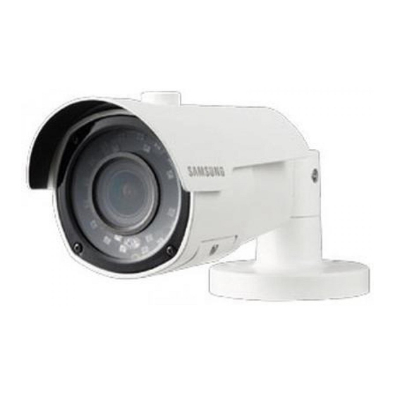
Component Name and Function Item Description Camera Bracket Camera Sunshield Knob Sunshield VIDEO OUTPUT jack: Video signals are output through this port. Connect this port to the Video IN port of an AHD DVR. Power input terminal: Connect the power as specified (DC 12V). Lens Screws of Lens Distance Adjustment Cover Lens Distance Adjustment Cover... -
Page 9: Installation
Installation BEFORE INSTALLATION Ensure you read out the following instructions before installing the camera: You have to check whether the location (ceiling or wall) can bear five times the weight of your camera. Don’t let the cable to be caught in improper place or the electric line cover to be damaged. Otherwise it may cause a breakdown or fire. - Page 10 3. Adjust camera position to make sure it points to the area you would like to monitor. FOCUS-LEVER FAR-NEAR ZOOM LEVER WIDE-TELE Lens Distance Adjustment Cover Please mind the installation position. Please do not touch the camera lens to avoid any dirt and dust...
-
Page 11: Adjustment Of The Monitoring Direction Of The Camera
Adjustment of the Monitoring Direction of the Camera Be able to adjust by 90-180 degrees vertically and by 0-360 degrees horizontally. Be able to adjust by 0-90 degrees vertically Adjust by 0-360 degrees horizontally ■ Adjust the monitoring direction Only adjust the camera direction after it is fixed on the ceiling. Images of some angles may be occluded by the camera housing. - Page 12 PROTECTION OF CABLE FROM WATER If this product is mounted outdoor, water leakage may occur at gap between cables. As shown below, butyl rubber (available on the market) shall be used to protect from water. 1. Connect power supply and BNC power source. 2.
-
Page 13: Connection And Installation
Connection and Installation Connection of DVR and monitor Connect the video output jack of the camera to the video input jack of DVR and monitor. Monitor Please refer to the manual attached with the device as the connection method varies ... -
Page 14: Use Of Communication
Resistance value of the copper wire when the temperature is [20° C(68° F)] #24 (0.22 mm² ) #22 (0.33 mm² ) #20 (0.52 mm² ) #18 (0.83 mm² ) Copper wire size (AWG) Resistance (Ω/m) 0.078 0.050 0.030 0.018 0.028 0.018 0.011 0.006... - Page 15 Connection and Installation - Video cable Connect the video output jack of the camera to the monitor with BNC coaxial cable, as shown below: Please use an auxiliary video amplifier if the distance between the camera and monitor exceeds the recommended maximum value. Recommended cable Distance specification...
-
Page 16: Camera Operations
Camera Operations 1. Camera Menus Step I: Open DVR main menu, and go to Device-> PTZ -> Protocol.(Based on DVR HRD-E430L/HRD-E830L/HRD-E1630L) Set Coax as Protocol. Step II: Go to live view interface, left click on the live channel and select the PTZ control icon【... - Page 17 2. Main menu MAIN MENU 1.EXPOSURE 2.BACKLIGHT 3.WHITE BAL 4.NR 5.SPECIAL 6.ADJUST 7.EXIT SAVE&END 1.EXPOSURE: (MAIN MENU→ EXPOSURE) EXPOSURE 1.SHUTTER AUTO 2.AGC ..|...13 3.SENS-UP 4.BRIGHTNESS ...|..32 5.D-WDR 6.DEFOG 7.RETURN SHUTTER NTSC: AUTO / FLK / 1/50,000sec~1/30sec / X2 ~ X30; PAL: AUTO / FLK / 1/50,000sec~1/25sec / X2 ~ X30 AUTO: Indicate automatically adjusting the shutter according to the light.
- Page 18 The larger the shutter value, the brighter the image, but the bigger the after image of the moving object. When the shutter value is small, there will be Noise, Spots and whiting, which is normal. AGC: 0-15 optional. The higher the gain level, the brighter the screen, but the more the noise. ...
- Page 19 DEFOG: DEFOG 1.POS/SIZE 2.GRADATION l....0 3.DEFAULT 4.RETURN POS/SIZE: POSITION and SIZE of setting area. GRADATION: Level 0 to 2 is optional. Higher the level, defog effect will be better. DEFAULT: Restore to default settings. RETURN: RET/SAVE&END The camera can automatically identify the fog density in the image with defog function, and it can vividly display the image even when the sight cannot be guaranteed to be clear as affected by the darkness or haze.
- Page 20 1.SELECT AREA1 2.DISPLAY 3.BLACK MASK 4.LEVEL ..|....20 5.MODE NIGHT 6.DEFAULT 7.RETURN SELECT: Selection of setting area (AREA1 TO AREA4) DISPLAY: POSITION and SIZE of setting area. BLACK MASK: Switch of setting area LEVEL: Strong light inhibition level (0-100). The strong light inhibition is more obvious with ...
- Page 21 WHITE BAL: MAIN MENU→WHITE BAL (ATW/AWC→SET/INDOOR/OUTDOOR/MANUAL/AWB) MAIN MENU 1.EXPOSURE 2.BACKLIGHT 3.WHITE BAL 4.NR 5.SPECIAL 6.ADJUST 7.EXIT SAVE&END ATW: When the color temperature is between 1,800K° and 10,500K°, set as ATW. AWC→SET: Set the white balance manually according to the current color temperature. INDOOR: When the color temperature is between 4,500K°...
- Page 22 In this case, please choose the "AWB" mode. ➊ When the color temperature of the object surroundings exceeds the control range (such as clear sky or sunset), choose the item. ➋ When the ambient light illumination of the subject is dark, if the camera faces towards the fluorescent lamp or installed in a place where the illumination changes significantly, the operation of "white balance"...
- Page 23 CAM TITLE Set to ON, move to the position of character you choose through the menu option key [ ] (Left, Right, Up and Down keys), and click [ ] to confirm. Repeat the step to input more characters. 15 characters can be entered at most. "←...
- Page 24 MOTION (OFF/ON) Whenever the illuminated object is detected to move in four areas of image, the product will send alarm so as to achieve effective monitoring. MOTION 1.SELECT AREA1 2.DISPLAY 3.SENSITIVITY ..|..64 4.COLOR GREEN 5.TRANS. 1.00 6.ALARM 7.DEFAULT 8.RETURN SELECT: 4 Areas optional.
- Page 25 BLOCK: After the MOTION alarm is triggered, the set MOTION area is displayed in a blocked area. OUTLINE: After the MOTION alarm is triggered, the set MOTION area is displayed in a area with border. ALL: After the MOTION alarm is triggered, the set MOTION area is displayed in a bordered grid area.
- Page 26 COLOR: Background of privacy zone in color. Click to select the background type and set the position and size of privacy zone. COLOR: Set the color in the privacy area. WHITE/BLACK/BLUE/YELLOW/GREEN/CYAN is optional. TRANS: Adjust the color transparency in the frame of the motion detection area. 0.25/0.50/0.75/1.00 is optional, and the larger the value, the higher the transparency.
- Page 27 The identification size may have errors due to different shapes of the object. In the following cases, the motion detection and the image analysis alarm performance may be reduced or abnormal operation may occur. The brightness or color of object may be similar to the background of image The position of image frame may move slightly Most motions occur continuously and randomly due to the influence of factors such as lens switching and rapid change of lighting...
-
Page 28: Troubleshooting
Troubleshooting Please refer to the following table if you have problems during camera operation. Please contact with the authorized technicians if your problem cannot be solved through the guidance. Problem Troubleshooting Check whether the power cable and the cable between There is no content displayed on ... -
Page 29: Specification
Specification HCO-E6070RN HCO-E6070RP Video Imaging Device 1/2.7" 2M CMOS Total Pixels 1952 x 1092 Effective Pixels 1920 x 1080 Scanning System Progressive Scan Min. Illumination 0 Lux(Auto IR LED on) S / N Ratio 52dB (AGC off) BNC(AHD, CVBS Selectable) BNC(AHD, CVBS Selectable) Video Output AHD : 30fps@1080p... - Page 30 HCO-E6070RN HCO-E6070RP Video Electronic Shutter AUTO / FLK / AUTO / FLK / Speed 1/50,000sec~1/30sec/X2 ~ X30 1/50,000sec~1/25sec/X2~X30 Reverse Off/Mirror/V-Flip/Rotate Protocol Video Transmission 300m(3C-2V) , 500m(5C-2V) Distance Environmental Operating Temperature / -30°C ~ +50°C (-22°F ~ +122°F) / Less than 90% RH Humidity Ingress Protection IP66...
- Page 31 Dimension Unit: mm...
- Page 32 This equipment has been tested and found to comply with the limits for a Class A digital device, pursuant to part 15 of the FCC Rules. These limits are designed to provide reasonable protection against harmful interference when the equipment is operated in a commercial environment. This equipment generates, uses, and can radiate radio frequency energy and, if not installed and used in accordance with the instruction manual, may cause harmful interference to radio communications.
- Page 33 Head Offi ce 86 Cheonggyecheon-ro Jung-gu Seoul 04541 Korea Tel +82.2.729.5277, 5254 Fax +82.2.729.5489 www.hanwha-security.com Hanwha Techwin America 100 Challenger Rd. Suite 700 Ridgefi eld Park, NJ 07660 Toll Free +1.877.213.1222 Direct +1.201.325.6920 Fax +1.201.373.0124 Hanwha Techwin Europe 2nd Floor, No. 5 The Heights, Brooklands, Weybridge, Surrey, KT13 0NY, UK Tel +44.1932.82.6700 Fax +44.1932.82.6701...