
Related Manuals for Samsung WDR-SV4


Summary of Contents for Samsung WDR-SV4
- Page 1 WDR-SV4 & SHC-735 Supreme Resolution WDR Camera User’s Manual Before attempting to connect or operate this product, please read these instructions carefully and save this manual for future use. ENGLISH...
-
Page 2: Table Of Contents
Contents How to Use the Camera Features Function Menu Structure Precautions How to Set up the Functions LENS Components and Accessories EXPOSURE WHITE BALANCE Overview BACKLIGHT Front View SSNR Side View DAY/NIGHT Bottom View IMAGE ADJ Rear View SPECIAL Installation Procedures EXIT Lens •... -
Page 3: Features
Features Samsung Techwin cares for the environment at all product manufacturing stages to preserve the environment, and is taking a number of steps to provide customers with more environment-friendly products.The Eco mark represents Samsung Techwin s will to create environment-friendly products,... -
Page 4: Precautions
Precautions Do not install under extreme Do not install in high humidity Do not drop the camera or Never keep the camera face to temperature conditions. environment. subject it to physical shock. strong light directly. Use only under temperature conditions May lower image quality. -
Page 5: Components And Accessories
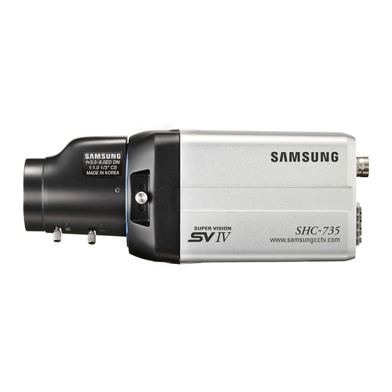
Components and Accessories Overview Front View 1. Ultra High Resolution WDR Color CCD Camera WDR-SV4 2. Auto Iris Lens Connector Plug 3. C-Mount Adapter Tripod Mounting Bracket Screw Hole Used to fix the Tripod Mounting Bracket to the top of the camera. -
Page 6: Side View
Overview Side View Bottom View Auto Iris Lens Connector Tripod Mounting Bracket Screw Hole Used to connect Auto Iris Lens plug. Used to fix the camera on a bracket or tripod. The screw sizes for this hole are as follows: 1/4"-20 UNC (20 THREAD) L:4.5mm±0.2mm (ISO standard), or 0.197"... -
Page 7: Rear View
Overview Installation Procedures Lens Rear View The lens is not supplied with this camera. Purchase a lens suitable for your environment. This camera accepts the auto iris lens and both C-and CS-mount lens. Notes • It is recommended to use the DC type Auto Iris Lens to effectively enjoy the major functions of this camera. -
Page 8: When Using C/Cs Mount Lens
Installation Procedures 3. Remove the cover of the auto iris lens connector plug and solder the lens cable to When Using C/CS Mount Lens the connector pin of the plug. Before installing a lens, identify whether the lens to be installed is a C-Mount or CS-Mount. •... -
Page 9: Connecting A Monitor
Installation Procedures • When Using a C Mount Lens Connecting a Monitor 1. Remove the protective glass cover at the front of this product and turn the C- Connect the Video OUT port on the rear panel of the camera to a monitor. Mount Adapter clockwise to install it. -
Page 10: Connecting Power
• To control the camera by constructing an additional controller, use Pelco-D Resistance value(Ω/m) 0.078 0.050 0.030 0.018 protocol or STW protocol (Samsung Techwin protocol). Voltage drop(V/m) 0.028 0.018 0.011 0.006 • As shown in the table above, voltage decreases as the wire gets longer. -
Page 11: How To Use The Camera
How to Use the Camera Function Menu Structure How to Set up the Functions You can set up functions using the 5 buttons on the rear of the camera. Setup Menu LENS • DC • VIDEO • MANUAL UP button SET button EXPOSURE •... -
Page 12: Lens
How to Use the Camera DC/Video : Select Auto Iris Lens MAIN SETUP 1.LENS Change the status using • When DC is selected, you can control screen brightness. The range of Select the function using the LEFT or RIGHT button. the UP or DOWN button. -
Page 13: Exposure
How to Use the Camera EXPOSURE Notes • To produce better results with A.FLK, do not use it in conjunction with the WDR MAIN SETUP mode of the BACKLIGHT menu. 1.LENS • When the SHUTTER is set to ESC after selecting the Internal Synchronization Type, the picture may become unstable if the camera faces a bright fluorescent 2.EXPOSURE light. -
Page 14: White Balance
How to Use the Camera White Balance (White Bal.) Notes • White Balance may not work properly under the following conditions. In this case Use the White Balance function to adjust the screen color. select the AWC mode. 1. When the SETUP menu screen is displayed, select ‘White Bal.’ by using the Up When the color temperature of environment surrounding the subject is out of the and Down buttons so that the arrow indicates ‘White Bal.’... - Page 15 How to Use the Camera WDR : When there are both bright and dark areas at the same time, this mode Notes makes both areas distinctive. • You cannot use the WDR mode when MANUAL or A.FLK mode in ‘SHUTTER’ OFF : Deactivates the WDR function.
-
Page 16: Day/Night
How to Use the Camera 3. Set the SSNR mode to ‘ON’ and press the SET button. Then you can adjust the 2. Select a desired mode using the Left and Right buttons according to the picture noise reduction level. display you want. -
Page 17: Image Adj
How to Use the Camera D-ZOOM : You can use a digital zoom of x1~x10. IMAGE ADJ. 1. When the SETUP menu screen is displayed, select ‘IMAGE ADJ.’ by using the Up and Down buttons so that the arrow indicates IMAGE ADJ. MAIN SETUP 1.LENS 2.EXPOSURE... - Page 18 How to Use the Camera Set it to ‘ON’ by using the Left and Right buttons. SPECIAL Notes Notes 1. When the SETUP menu screen is displayed, select ‘SPECIAL’ by using the Up and Down buttons so that the arrow indicates ‘SPECIAL’. •...
- Page 19 How to Use the Camera Enter a title, move the cursor to ’POS’ and press the SET button. The entered When the SPECIAL menu screen is displayed, press the Up and Down buttons title appears on the screen. Select the position to display the title on the so that the arrow indicates MOTION DET .
-
Page 20: Exit
How to Use the Camera Troubleshooting - MASK COLOR : Determine area color. You can select Gray, Green, Red, Blue, Black, If you have trouble operating your camera, refer to the following table. White. If the guidelines do not enable you to solve the problem, contact an authorized - TRANSP : Determine the transparency of selected area as controlling number from 0 to 3. -
Page 21: Specifications
Troubleshooting Specifications SHC-735N SHC-735P Problem Solution Input Voltage AC24V / DC12V POWER Power Consumption 4.0W The Motion Detection • Check that MOTION DEF of SPECIAL SETUP menu Size Diagonal 6mm (1/3") Sony DS CCD function does not is ‘OFF’. Total Pixels 811(H) x 508(V) 795(H) x 596(V) work. - Page 22 DECLARATION OF CONFORMITY MEMO Application of Council Directive(s) 89 / 336 / EEC Manufacturer's Name SAMSUNG TECHWIN CO., LTD Manufacturer's Address SAMSUNG TECHWIN CO., LTD 42, SUNGJU-DONG CHANGWON-CITY, KYUNGNAM, KOREA, 641-716 European Representative Name European Representative Address Equipment Type/Environment CCTV Camera...
- Page 23 The lightning flash with an arrowhead symbol, within an equilateral triangle is intended to alert the user to the presence of uninsulated “dangerous voltage” within the product's enclosure that may be of sufficient magnitude to constitute a risk of electric shock to persons. The exclamation point within an equilateral triangle is intended to alert the user to the presence of important operating and maintenance (servicing) instructions in the literature accompanying the appliance.