
Related Manuals for HPE ProLiant SL270s Gen8


Summary of Contents for HPE ProLiant SL270s Gen8
- Page 1 HPE ProLiant SL270s Gen8 Server User Guide Abstract This document provides detailed instructions to configure and use the HPE ProLiant SL270s Gen8 Server. Part Number: 666300-001R January 2016 Edition: 2...
- Page 2 © Copyright 2012, 2016 Hewlett Packard Enterprise Development LP The information contained herein is subject to change without notice. The only warranties for Hewlett Packard Enterprise products and services are set forth in the express warranty statements accompanying such products and services. Nothing herein should be construed as constituting an additional warranty.
-
Page 3: Table Of Contents
Register the product ............................... 25 Hardware options installation ....................... 26 Introduction ................................26 Processor option ..............................26 Memory options ..............................30 HPE SmartMemory............................30 Memory subsystem architecture........................31 Single-, dual-, and quad-rank DIMMs ......................31 DIMM identification ............................32 Memory configurations ..........................32 General DIMM slot population guidelines .................... - Page 4 Hewlett Packard Enterprise product QuickSpecs ....................74 HPE iLO Management ............................74 HPE iLO............................... 74 Intelligent Provisioning..........................76 HPE Insight Remote Support ........................77 Scripting Toolkit for Windows and Linux...................... 77 Service Pack for ProLiant ............................78 HP Smart Update Manager ......................... 78 HPE ROM-Based Setup Utility ..........................
- Page 5 Specifications ............................90 Environmental specifications ..........................90 Server specifications .............................. 90 Hot-plug power supply calculations ........................90 Support and other resources........................ 91 Accessing Hewlett Packard Enterprise Support ..................... 91 Information to collect ........................... 91 Accessing updates ..............................91 Websites ................................. 91 Customer Self Repair .............................
-
Page 6: Component Identification
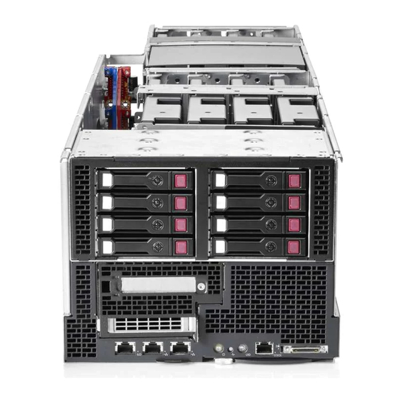
Component identification Front panel components Item Description Hot-plug drive 1 Hot-plug drive 2 Hot-plug drive 3 Hot-plug drive 4 Hot-plug drive 5 Hot-plug drive 6 Hot-plug drive 7 Hot-plug drive 8 Option bay 2, FlexibleLOM Option bay 1, PCI riser board iLO 4 connector NIC 2 connector NIC 1 connector... -
Page 7: Front Panel Leds And Buttons
Front panel LEDs and buttons Item Description Status iLO 4 speed LED Green = LAN connection using a GbE link Amber = LAN connection using a 10 Mbps/100 Mbps link Off = No link exists iLO 4 status LED Solid green = Link to network Flashing green (1 Hz/cycle per sec) = Network active Off = No network activity NIC 2 status LED... -
Page 8: Rear Panel Components
Rear panel components The server has four power supplies, eight fans, and a single SLAPM interface located on the rear panel of the chassis. Item Description SLAPM interface Power supply 4 Power supply 3 Power supply 2 Power supply 1 Rear panel LEDs and buttons Item Description... -
Page 9: System Board Components
Item Description Status Amber—Fan has failed. UID LED button Blue—Activated Flashing blue—System is being remotely managed. Off—Deactivated Fan 4/12 power LED Off—Normal Amber—Fan has failed. Fan 3/11 power LED Off—Normal Amber—Fan has failed. Fan 1/9 power LED Off—Normal Amber—Fan has failed. Fan 2/10 power LED Off—Normal Amber—Fan has failed. -
Page 10: Dimm Slot Locations
Item Description System battery Processor socket 2 Processor 2 DIMM slots 12-pin system board power connector 24-pin RPS connector Processor 1 DIMM slots Processor socket 1 Mini-SAS connector 2i Mini-SAS connector 1i microSD card slot Hot-plug drive backplane sideband connector FlexibleLOM x16 riser connector System maintenance switch TPM connector... -
Page 11: System Maintenance Switch
System maintenance switch Position Default Function Off = iLO 4 security is enabled. On = iLO 4 security is disabled. Off = System configuration can be changed. On = System configuration is locked. Reserved Reserved Off = Power-on password is enabled. On = Power-on password is disabled. -
Page 12: Device Numbers
Device numbers Item Description Hard drive 1 Hard drive 2 Hard drive 3 Hard drive 4 Hard drive 5 Hard drive 6 Hard drive 7 Hard drive 8 GPU numbering • Left node Component identification 12... -
Page 13: Hot-Plug Drive Led Definitions
• Right node Hot-plug drive LED definitions Item Status Definition The drive is being identified by a host application. Locate Solid blue Flashing blue The drive carrier firmware is being updated or requires an update. Activity ring Rotating green Drive activity No drive activity Do not remove Solid white... -
Page 14: Operations
Operations Power up the server To power up the server, press the Power On/Standby button. Power down the server Before powering down the server for any upgrade or maintenance procedures, perform a backup of critical server data and programs. IMPORTANT: When the server is in standby mode, auxiliary power is still being provided to the system. -
Page 15: Remove The Processor Air Baffle
Remove the server from the chassis. Remove the processor air baffle To remove the component: Power down the server (on page 14). Disconnect all peripheral cables from the server. Remove the server from the chassis (on page 14). Remove the shipping brackets. Operations 15... - Page 16 Remove the shipping plates. Remove the hard drive cage. Operations 16...
- Page 17 Loosen screws securing the GPU shelf. Remove the GPU shelf. Operations 17...
- Page 18 Remove the processor air baffle. To replace the component, reverse the removal procedure. Operations 18...
-
Page 19: Setup
Delivered by experienced, certified engineers, HP Care Pack services help you keep your servers up and running with support packages tailored specifically for HPE ProLiant systems. HP Care Packs let you integrate both hardware and software support into a single package. A number of service level options are available to meet your needs. -
Page 20: Space And Airflow Requirements
Space and airflow requirements To allow for servicing and adequate airflow, observe the following space and airflow requirements when deciding where to install a rack: • Leave a minimum clearance of 63.5 cm (25 in) in front of the rack. •... -
Page 21: Power Requirements
For more information on the hot-plug power supply and calculators to determine server power consumption in various system configurations, see the Hewlett Packard Enterprise Power Advisor website (http://www.hpe.com/info/rackandpower). Electrical grounding requirements The server must be grounded properly for proper operation and safety. In the United States, you must install the equipment in accordance with NFPA 70, 1999 Edition (National Electric Code), Article 250, as well as any local and regional building codes. -
Page 22: Contents Of The Server Shipping Carton
Install any hardware options before initializing the server. For options installation information, see the documentation that ships with the option. For server-specific information, see the server user guide on the Hewlett Packard Enterprise website (http://www.hpe.com/info/enterprise/docs). Installing the components WARNING: The server is very heavy. To reduce the risk of personal injury or damage to the equipment: •... -
Page 23: Installing The Server Into The Chassis
Before installing front or rear components into the chassis, review chassis bay numbering for each component. For slot numbering information, see the quick setup instructions. Based on the total number ordered and the planned configuration, install the following components: • Nodes •... -
Page 24: Powering Up The Chassis
If you do not need to modify the server configuration and are ready to install the system software, press F10 to access Intelligent Provisioning. NOTE: If an HPE Smart Array controller has been added or is embedded in the system, the controller defaults to a RAID configuration based on the size and number of drives installed. -
Page 25: Register The Product
Intelligent Provisioning automatically integrates optimized ProLiant server support software from the SPP. SPP replaces the HPE Smart Update Firmware DVD and ProLiant Support Pack (PSP). For more information on using SPP, see the Service Pack for ProLiant User Guide on the Documentation CD or the Intelligent Provisioning Information Library. -
Page 26: Hardware Options Installation
Hardware options installation Introduction If more than one option is being installed, read the installation instructions for all the hardware options and identify similar steps to streamline the installation process. WARNING: To reduce the risk of personal injury from hot surfaces, allow the drives and the internal system components to cool before touching them. - Page 27 Open each of the processor locking levers in the order indicated, and then open the processor retaining bracket. Remove the clear processor socket cover. Retain the processor socket cover for future use. Hardware options installation 27...
- Page 28 Install the processor. Verify that the processor is fully seated in the processor retaining bracket by visually inspecting the processor installation guides on either side of the processor. THE PINS ON THE SYSTEM BOARD ARE VERY FRAGILE AND EASILY DAMAGED. CAUTION: THE PINS ON THE SYSTEM BOARD ARE VERY FRAGILE AND EASILY DAMAGED.
- Page 29 Press and hold the processor retaining bracket in place, and then close each processor locking lever. Press only in the area indicated on the processor retaining bracket. Remove the thermal interface protective cover from the heatsink. CAUTION: Heatsinks specified for processor 1 and 2 are not interchangeable. Be sure to note the appropriate orientation on the heatsink label.
-
Page 30: Memory Options
HPE SmartMemory HPE SmartMemory, introduced for Gen8 servers, authenticates and unlocks certain features available only on HPE Qualified memory and verifies whether installed memory has passed Hewlett Packard Enterprise qualification and test processes. Qualified memory is performance-tuned for HPE ProLiant and BladeSystem servers and provides future enhanced support through HPE Active Health and manageability software. -
Page 31: Memory Subsystem Architecture
while the industry supports DDR3-1333 RDIMM at 1.5V, this Gen8 server supports DDR3-1333 RDIMM at 1.35V. This difference equates to up to 20% less power at the DIMM level with no performance penalty. Memory subsystem architecture The memory subsystem in this server is divided into channels. Each processor supports four channels, and each channel supports two DIMM slots, as shown in the following table. -
Page 32: Dimm Identification
L = LRDIMM (load reduced) For the latest supported memory information, see the QuickSpecs on the Hewlett Packard Enterprise website (http://www.hpe.com/info/qs). At the website, choose the geographic region, and then locate the product by name or product category. Memory configurations To optimize server availability, the server supports the following AMP modes: •... - Page 33 Advanced ECC provides additional protection over Standard ECC because it is possible to correct certain memory errors that would otherwise be uncorrected and result in a server failure. Using HPE Advanced Memory Error Detection technology, the server provides notification when a DIMM is degrading and has a higher probability of uncorrectable memory error.
-
Page 34: General Dimm Slot Population Guidelines
For DIMM spare replacement, install the DIMMs per slot number as instructed by the system software. For detailed memory configuration rules and guidelines, use the Online DDR3 Memory Configuration Tool on the Hewlett Packard Enterprise website (http://www.hpe.com/info/ddr3memory-configurator). DIMM speeds are supported as indicated in the following table. Populated slots... -
Page 35: Installing A Dimm
Lockstep Memory population guidelines For Lockstep memory mode configurations, observe the following guidelines: • Observe the general DIMM slot population guidelines (on page 34). • DIMM configuration on all channels of a processor must be identical. • In multi-processor configurations, each processor must have a valid Lockstep Memory configuration. •... - Page 36 Remove the shipping plates. Remove the hard drive cage. Hardware options installation 36...
- Page 37 Loosen screws securing the GPU shelf. Remove the GPU shelf. Remove the processor air baffle (on page 15). Open the DIMM slot latches. Hardware options installation 37...
-
Page 38: Hot-Plug Hard Drive Guidelines
23). Power up the server (on page 14). After installing the DIMMs, to configure memory protection mode, use RBSU ("HPE ROM-Based Setup Utility" on page 78). Hot-plug hard drive guidelines When adding hard drives to the server, observe the following general guidelines: •... -
Page 39: Removing The Hard Drive Blank
Removing the hard drive blank Remove the component as indicated. Installing a hot-plug SAS drive Remove the drive blank. Prepare the drive. Hardware options installation 39... -
Page 40: Controller Options
("Hot-plug drive LED definitions" on page 13). Controller options The server ships with HPE Smart Array H220i Controller. For more information about the storage controller and its features, select the relevant controller user documentation on the Hewlett Packard Enterprise website (http://www.hpe.com/support/SAC_UG_ProLiantServers_en). -
Page 41: Installing The Cache Module
NOTE: The data protection and the time limit also apply if a power outage occurs. When power is restored to the system, an initialization process writes the preserved data to the hard drives. Installing the cache module CAUTION: In systems that use external data storage, be sure that the server is the first unit to be powered down and the last to be powered back up. - Page 42 Remove the hard drive cage. Loosen screws securing the GPU shelf. Hardware options installation 42...
-
Page 43: Installing The Fbwc Capacitor Pack
Remove the GPU shelf. Install the cache module in the SAS cache module connector on the system board. For connector locations, see "System board components (on page 9)." Install all components removed from the server. Install the server into the chassis ("Installing the server into the chassis"... - Page 44 Power down the server (on page 14). Disconnect all peripheral cables from the server. Remove the server from the chassis (on page 14). Remove all shipping brackets. Remove the shipping plates. Hardware options installation 44...
- Page 45 Remove the hard drive cage. Loosen screws securing the GPU shelf. Hardware options installation 45...
- Page 46 Remove the GPU shelf. Install the FBWC module into the holder mounted in the server tray. Route the FBWC cable as indicated: Hardware options installation 46...
- Page 47 Left node Right node Hardware options installation 47...
-
Page 48: Expansion Board Options
Attach the FBWC cable to the cache module on the system board or to the controller card. Install all components removed from the server. Install the server into the chassis ("Installing the server into the chassis" on page 23). Power up the server (on page 14). Expansion board options Installing an expansion board or FlexibleLOM The server ships with PCIe riser boards and expansion slots. - Page 49 Remove the shipping plates. Remove the hard drive cage. Hardware options installation 49...
- Page 50 Loosen screws securing the GPU shelf. Remove the GPU shelf. Hardware options installation 50...
- Page 51 Remove the PCI/FlexibleLOM riser cage. Remove the expansion slot cover from the PCI/FlexibleLOM riser cage. IMPORTANT: If the expansion board ships with an extender bracket, remove it from the expansion board before inserting the board into the expansion slot of the PCI riser board assembly.
-
Page 52: Installing A Pci Riser Board Assembly
FlexibleLOM Expansion board Connect all internal or external cabling to the installed board. Install the GPU cage Install the SFF hot-plug drive cage. Install the shipping brackets. Install the server into the chassis ("Installing the server into the chassis" on page 23). Connect the peripheral cables. - Page 53 Remove all shipping brackets. Remove the shipping plates. Hardware options installation 53...
- Page 54 Remove the hard drive cage. Loosen screws securing the GPU shelf. Hardware options installation 54...
- Page 55 Remove the GPU shelf. Remove the PCI cage. Hardware options installation 55...
-
Page 56: Redundant Hot-Plug Power Supply Option
Install the riser card into the PCI cage. If necessary, install the expansion boards ("Installing an expansion board or FlexibleLOM" on page 48). IMPORTANT: The server does not power up if the PCI riser board assembly is not seated properly. Connect all internal cabling to the expansion boards. - Page 57 Remove the power supply blank. Remove the protective cover from the connector pins on the power supply. WARNING: To reduce the risk of electric shock or damage to the equipment, do not connect the power cord to the power supply until the power supply is installed. Hardware options installation 57...
-
Page 58: Installing The 8X Sff Smart Array Enablement Option
Install the power supply into the bay until it clicks. Connect the power cord to the power supply. Route the power cord through the cable management solution. Connect the power cord to the power source. Be sure that the power supply LED is green. Installing the 8X SFF Smart Array enablement option Power down the server (on page 14). - Page 59 Remove the shipping plates. Remove the hard drive cage. Hardware options installation 59...
- Page 60 Loosen screws securing the GPU shelf. Remove the GPU shelf. Hardware options installation 60...
- Page 61 Remove the PCI cage. Install the riser card into the PCI cage. Hardware options installation 61...
- Page 62 Install the controller card into the PCI cage. Disconnect the existing mini-SAS cables from the SFF HDD cage. Hardware options installation 62...
- Page 63 Install the mini-SAS cable included in this kit to the HDD cage. Connect the mini-SAS cable to the SAS connection on the controller card. Left node Hardware options installation 63...
-
Page 64: Connecting The Suv Cable
Right node Install all components removed from the server. Install the server into the chassis ("Installing the server into the chassis" on page 23). Power up the server (on page 14). Connecting the SUV cable CAUTION: Before disconnecting the SUV cable from the connector, always squeeze the release buttons on the sides of the connector. -
Page 65: Hp Trusted Platform Module Option
HP Trusted Platform Module option For more information about product features, specifications, options, configurations, and compatibility, see the product QuickSpecs on the Hewlett Packard Enterprise website (http://www.hpe.com/info/qs). The TPM is not a customer-removable part. CAUTION: Any attempt to remove an installed TPM from the system board breaks or disfigures the TPM security rivet. - Page 66 Power down the server (on page 14). Disconnect all peripheral cables from the server. Remove the server from the chassis (on page 14). Remove all shipping brackets. Remove the shipping plates. Hardware options installation 66...
- Page 67 Remove the hard drive cage. Loosen screws securing the GPU shelf. Hardware options installation 67...
- Page 68 Remove the GPU shelf. CAUTION: Any attempt to remove an installed TPM from the system board breaks or disfigures the TPM security rivet. Upon locating a broken or disfigured rivet on an installed TPM, administrators should consider the system compromised and take appropriate measures to ensure the integrity of the system data.
-
Page 69: Retaining The Recovery Key/Password
Install the TPM security rivet by pressing the rivet firmly into the system board. Install the GPU cage Install the SFF hot-plug drive cage. Install the shipping brackets and shipping plates. Install the server into the chassis ("Installing the server into the chassis"... - Page 70 For more information on firmware updates and hardware procedures, see the HP Trusted Platform Module Best Practices White Paper on the Hewlett Packard Enterprise website (http://www.hpe.com/support/hpesc). For more information on adjusting TPM usage in BitLocker™, see the Microsoft website (http://technet.microsoft.com/en-us/library/cc732774.aspx).
-
Page 71: Cabling
For information on cabling peripheral components, refer to the white paper on high-density deployment at the Hewlett Packard Enterprise website (http://www.hpe.com/products/servers/platforms). CAUTION: When routing cables, always be sure that the cables are not in a position where they can be pinched or crimped. - Page 72 • Right node • Capacitor pack to FBWC on controller card cabling: Left node Cabling 72...
- Page 73 Right node Cabling 73...
-
Page 74: Software And Configuration Utilities
For more information about product features, specifications, options, configurations, and compatibility, see the product QuickSpecs on the Hewlett Packard Enterprise website (http://www.hpe.com/info/qs). HPE iLO Management HPE iLO Management is a set of embedded management features supporting the complete lifecycle of the server, from initial deployment through ongoing management. HPE iLO The iLO 4 subsystem is a standard component of ProLiant servers that simplifies initial server setup, server health monitoring, power and thermal optimization, and remote server administration. - Page 75 The data that is collected is managed according to the Hewlett Packard Enterprise Data Privacy policy. For more information see the Hewlett Packard Enterprise website (http://www.hpe.com/info/privacy). Software and configuration utilities 75...
-
Page 76: Intelligent Provisioning
The Agentless Management Service is available in the SPP, which can be downloaded from the Hewlett Packard Enterprise website (http://www.hpe.com/servers/spp/download). The Active Health System log can be downloaded manually from iLO 4 or HPE Intelligent Provisioning and sent to Hewlett Packard Enterprise. -
Page 77: Hpe Insight Remote Support
For more information, see Insight Remote Support and Insight Online Setup Guide for ProLiant Servers and BladeSystem c-Class Enclosures on the Hewlett Packard Enterprise website (http://www.hpe.com/info/insightremotesupport/docs). Insight Remote Support is available as part of Hewlett Packard Enterprise Warranty, HP Care Pack Service, or Hewlett Packard Enterprise contractual support agreement. -
Page 78: Service Pack For Proliant
To access the HP Smart Update Manager User Guide, see the HP SUM Information Library (http://www.hpe.com/info/hpsum/documentation). HPE ROM-Based Setup Utility RBSU is a configuration utility embedded in HPE ProLiant servers that performs a wide range of configuration activities that can include the following: •... -
Page 79: Auto-Configuration Process
For more information on RBSU, see the ROM-Based Setup Utility User Guide on the Documentation CD or the RBSU Information Library (http://www.hpe.com/info/rbsu/docs). Boot options Near the end of the boot process, the boot options screen is displayed. This screen is visible for several seconds before the system attempts to boot from a supported boot device. -
Page 80: Configuring Amp Modes
Array Configuration Utility ACU is a utility with the following features: • Runs as a local application or remote service accessed through the HPE System Management Homepage • Supports online array capacity expansion, logical drive extension, assignment of online spares, and RAID or stripe size migration •... -
Page 81: Option Rom Configuration For Arrays
For more information about the storage controller and its features, select the relevant controller user documentation on the Hewlett Packard Enterprise website (http://www.hpe.com/info/smartstorage/docs). To configure arrays, see the HPE Smart Storage Administrator User Guide on the Hewlett Packard Enterprise website (http://www.hpe.com/info/smartstorage/docs). -
Page 82: Rompaq Utility
ASR is a feature that causes the system to restart when a catastrophic operating system error occurs, such as a blue screen, ABEND (does not apply to HPE ProLiant DL980 Servers), or panic. A system fail-safe timer, the ASR timer, starts when the System Management driver, also known as the Health Driver, is loaded. -
Page 83: Keeping The System Current
SPP, see the Hewlett Packard Enterprise website (http://www.hpe.com/servers/spp/download). To locate the drivers for a particular server, go to the Hewlett Packard Enterprise Support Center website (http://www.hpe.com/support/hpesc). Under Select your HPE product, enter the product name or number and click Go. -
Page 84: Operating Systems And Virtualization Software Support For Proliant Servers
HPE Proactive Care—For customers running business critical environments where downtime is not an option, HPE Proactive Care helps to deliver high levels of availability. Key to these service options is the delivery of proactive service management tools to help you avoid the causes of downtime. If a problem arises, then Hewlett Packard Enterprise offers advanced technical response from critical system support specialists for problem identification and resolution. -
Page 85: Troubleshooting
• Japanese (http://www.hpe.com/support/Gen9_TSG_ja) • Simplified Chinese (http://www.hpe.com/support/Gen9_TSG_zh_cn) The ProLiant Gen8 Troubleshooting Guide, Volume II: Error Messages provides a list of error messages and information to assist with interpreting and resolving error messages on ProLiant servers and server blades. To view the guide, select a language: •... - Page 86 Remove the shipping brackets and shipping plates. Remove the SFF hot-plug drive cage. Remove the GPU cage. Remove the PCI/FlexibleLOM riser cage. Locate the battery on the system board ("System board components" on page 9). Remove the battery. IMPORTANT: Replacing the system board battery resets the system ROM to its default configuration.
-
Page 87: Warranty And Regulatory Information
Warranty and regulatory information Warranty information HPE ProLiant and x86 Servers and Options (http://www.hpe.com/support/ProLiantServers-Warranties) HPE Enterprise Servers (http://www.hpe.com/support/EnterpriseServers-Warranties) HPE Storage Products (http://www.hpe.com/support/Storage-Warranties) HPE Networking Products (http://www.hpe.com/support/Networking-Warranties) Regulatory information Safety and regulatory compliance For important safety, environmental, and regulatory information, see Safety and Compliance Information for Server, Storage, Power, Networking, and Rack Products, available at the Hewlett Packard Enterprise website (http://www.hpe.com/support/Safety-Compliance-EnterpriseProducts). -
Page 88: Turkey Rohs Material Content Declaration
• Russia: • Belarus: • Kazakhstan: Manufacturing date: The manufacturing date is defined by the serial number. CCSYWWZZZZ (serial number format for this product) Valid date formats include: • YWW, where Y indicates the year counting from within each new decade, with 2000 as the starting point;... -
Page 89: Electrostatic Discharge
Electrostatic discharge Preventing electrostatic discharge To prevent damaging the system, be aware of the precautions you need to follow when setting up the system or handling parts. A discharge of static electricity from a finger or other conductor may damage system boards or other static-sensitive devices. -
Page 90: Specifications
21.32 kg (47.00 lb) Weight (maximum: two processors, eight hard drives) Hot-plug power supply calculations For hot-plug power supply specifications and calculators to determine electrical and heat loading for the server, see the Hewlett Packard Enterprise Power Advisor website (http://www.hpe.com/info/rackandpower). Specifications 90... -
Page 91: Support And Other Resources
Hewlett Packard Enterprise Support Center. You must have an HP Passport set up with relevant entitlements. Websites • Hewlett Packard Enterprise Information Library (http://www.hpe.com/info/enterprise/docs) • Hewlett Packard Enterprise Support Center (http://www.hpe.com/support/hpesc) • Contact Hewlett Packard Enterprise Worldwide (http://www.hpe.com/assistance) -
Page 92: Customer Self Repair
Single Point of Connectivity Knowledge (SPOCK) Storage compatibility matrix (http://www.hpe.com/storage/spock) • Storage white papers and analyst reports (http://www.hpe.com/storage/whitepapers) Customer Self Repair Hewlett Packard Enterprise products are designed with many Customer Self Repair (CSR) parts to minimize repair time and allow for greater flexibility in performing defective parts replacement. If during... - Page 93 Pour plus d'informations sur le programme CSR de Hewlett Packard Enterprise, contactez votre Mainteneur Agrée local. Pour plus d'informations sur ce programme en Amérique du Nord, consultez le site Web Hewlett Packard Enterprise (http://www.hpe.com/support/selfrepair). Riparazione da parte del cliente Per abbreviare i tempi di riparazione e garantire una maggiore flessibilità nella sostituzione di parti difettose, i prodotti Hewlett Packard Enterprise sono realizzati con numerosi componenti che possono essere riparati direttamente dal cliente (CSR, Customer Self Repair).
- Page 94 Weitere Informationen über das Hewlett Packard Enterprise Customer Self Repair Programm erhalten Sie von Ihrem Servicepartner vor Ort. Informationen über das CSR-Programm in Nordamerika finden Sie auf der Hewlett Packard Enterprise Website unter (http://www.hpe.com/support/selfrepair). Reparaciones del propio cliente Los productos de Hewlett Packard Enterprise incluyen muchos componentes que el propio usuario puede reemplazar (Customer Self Repair, CSR) para minimizar el tiempo de reparación y ofrecer una mayor...
- Page 95 Packard Enterprise, póngase en contacto con su proveedor de servicios local. Si está interesado en el programa para Norteamérica, visite la página web de Hewlett Packard Enterprise CSR (http://www.hpe.com/support/selfrepair). Customer Self Repair Veel onderdelen in Hewlett Packard Enterprise producten zijn door de klant zelf te repareren, waardoor de reparatieduur tot een minimum beperkt kan blijven en de flexibiliteit in het vervangen van defecte onderdelen groter is.
- Page 96 Para obter mais informações sobre o programa de reparo feito pelo cliente da Hewlett Packard Enterprise, entre em contato com o fornecedor de serviços local. Para o programa norte-americano, visite o site da Hewlett Packard Enterprise (http://www.hpe.com/support/selfrepair). Support and other resources 96...
- Page 97 Support and other resources 97...
- Page 98 Support and other resources 98...
-
Page 99: Remote Support
Hewlett Packard Enterprise, which will initiate a fast and accurate resolution based on your product’s service level. Hewlett Packard Enterprise strongly recommends that you register your device for remote support. For more information and device support details, go to the Insight Remote Support website (http://www.hpe.com/info/insightremotesupport/docs). Support and other resources 99... -
Page 100: Acronyms And Abbreviations
Acronyms and abbreviations ABEND abnormal end Array Configuration Utility Advanced Data Mirroring Advanced Memory Protection Automatic Server Recovery baseboard management controller Canadian Standards Association Customer Self Repair DDDC Double Device Data Correction double data rate FBWC flash-backed write cache graphics processing unit HP SUM HP Smart Update Manager Acronyms and abbreviations 100... - Page 101 International Electrotechnical Commission Integrated Lights-Out Integrated Management Log large form factor LRDIMM load reduced dual in-line memory module nonmaskable interrupt NVRAM nonvolatile memory ORCA Option ROM Configuration for Arrays PCIe Peripheral Component Interconnect Express PCI-X peripheral component interconnect extended POST Power-On Self Test RBSU ROM-Based Setup Utility...
- Page 102 SATA serial ATA SDDC Single Device Data Correction small form factor Systems Insight Manager SLAPM SL Advanced Power Manager Service Pack for ProLiant serial, USB, video TMRA recommended ambient operating temperature Trusted Platform Module UDIMM unregistered dual in-line memory module unit identification uninterruptible power system universal serial bus...
-
Page 103: Documentation Feedback
Hewlett Packard Enterprise is committed to providing documentation that meets your needs. To help us improve the documentation, send any errors, suggestions, or comments to Documentation Feedback (mailto:docsfeedback@hpe.com). When submitting your feedback, include the document title, part number, edition, and publication date located on the front cover of the document. For online help content, include the product name, product version, help edition, and publication date located on the legal notices page. -
Page 104: Index
LEDs 6 Hewlett Packard Enterprise website 91 Declaration of Conformity 87, 88 HP Trusted Platform Module option 65, 69 default settings 33 HPE Insight Diagnostics 76, 77 device numbers 12 HPE SmartMemory 30 diagnosing problems 85 diagnostic tools 74, 76, 82... - Page 105 rack warnings 21 RBSU (ROM-Based Setup Utility) 74, 78, 79, 80 Japanese notice 87 RBSU configuration 78 rear panel components 8 rear panel LEDs 8 redundant power supply 56 LEDs 8, 13 redundant ROM 82 LEDs, drive 13 regulatory compliance notices 87, 88 LEDs, hard drive 13 remote support and analysis tools 77 LEDs, power supply 8...
- Page 106 ventilation 19 warnings 21 website, Hewlett Packard Enterprise 91 Index 106...
Need help?
Do you have a question about the ProLiant SL270s Gen8 and is the answer not in the manual?
Questions and answers