Siemens SITRANS FUS060 Operating Instructions Manual
Ultrasonic flowmeters with profibus pa
Hide thumbs
Also See for SITRANS FUS060:
- Operating instructions manual (52 pages) ,
- Quick start manual (17 pages) ,
- Operating instructions manual (122 pages)
Table of Contents
Advertisement
Quick Links
SITRANS F
Ultrasonic Flowmeters
SITRANS FUS060 with PROFIBUS PA
Operating Instructions
7ME305 (FUS060 with PROFIBUS PA)
09/2021
A5E02225054-AD
Introduction
Safety notes
Description
Installing/Mounting
Connecting
Commissioning
Functions
Service and maintenance
Troubleshooting/FAQs
Technical specifications
Dimension drawings
Product documentation and
support
PROFIBUS communication
PROFIBUS parameters
HMI menu structure
1
2
3
4
5
6
7
8
9
10
11
A
B
C
D
Advertisement
Table of Contents

Related Manuals for Siemens SITRANS FUS060


Summary of Contents for Siemens SITRANS FUS060
- Page 1 Introduction Safety notes Description SITRANS F Installing/Mounting Ultrasonic Flowmeters SITRANS FUS060 with PROFIBUS PA Connecting Commissioning Operating Instructions Functions Service and maintenance Troubleshooting/FAQs Technical specifications Dimension drawings Product documentation and support PROFIBUS communication PROFIBUS parameters 7ME305 (FUS060 with PROFIBUS PA)
- Page 2 Note the following: WARNING Siemens products may only be used for the applications described in the catalog and in the relevant technical documentation. If products and components from other manufacturers are used, these must be recommended or approved by Siemens. Proper transport, storage, installation, assembly, commissioning, operation and maintenance are required to ensure that the products operate safely and without any problems.
-
Page 3: Table Of Contents
Connecting ............................31 Wiring the transducer cables ....................33 Wiring output and power supply ..................35 Wiring PROFIBUS PA ......................37 Commissioning ............................ 41 Start up ..........................41 Operating the device......................41 SITRANS FUS060 with PROFIBUS PA Operating Instructions, 09/2021, A5E02225054-AD... - Page 4 Cyclic Data Transmission ....................89 Acyclic Data Transmission....................90 Input Data (from Slave to Master)..................90 Status bytes ........................91 Output Data (from Master to Slave) ..................94 Diagnostics ........................94 SITRANS FUS060 with PROFIBUS PA Operating Instructions, 09/2021, A5E02225054-AD...
- Page 5 Menu 4 - Device outputs ....................111 D.1.5 Menu 5 - Identification ..................... 112 D.1.6 Menu 6 - Service ......................113 D.1.7 Menu 7 - Sensor parameters..................... 116 Index ..............................123 SITRANS FUS060 with PROFIBUS PA Operating Instructions, 09/2021, A5E02225054-AD...
- Page 6 Table of contents SITRANS FUS060 with PROFIBUS PA Operating Instructions, 09/2021, A5E02225054-AD...
-
Page 7: Introduction
For flowmeters based on the FUS060 transmitter various technical literature such as operating instructions and quick start guides are available on the CD-ROM shipped with the device, or it can be found on the Internet at www.siemens.com/flowdocumentation, where further information on the SITRANS F flowmeter range is also available. -
Page 8: Designated Use
Risk of explosion in hazardous areas. • Do not use damaged or incomplete devices. Items supplied • SITRANS FUS060 • Wall mounting bracket (standard only) • SITRANS F documentation disk • Quick Start guide SITRANS FUS060 with PROFIBUS PA Operating Instructions, 09/2021, A5E02225054-AD... -
Page 9: Security Information
Siemens’ products and solutions undergo continuous development to make them more secure. Siemens strongly recommends that product updates are applied as soon as they are available and that the latest product versions are used. Use of product versions that are no longer supported, and failure to apply the latest updates may increase customer’s exposure to cyber... -
Page 10: How To Read The Operating Instructions
The content reflects the technical status at the time of publishing. Siemens reserves the right to make technical changes in the course of further development. -
Page 11: Safety Notes
Material compatibility Siemens Flow Instruments can provide assistance with the selection of wetted sensor parts. However, the full responsibility for the selection rests with the customer and Siemens Flow Instruments can take no responsibility for any failure due to material incompatibility. -
Page 12: Installation In Hazardous Area
• PTB 07 ATEX 2033 X with the marking: II 2 G Ex db eb mb [ia Ga] IIC T6…T3 Gb The device's compliance with Essential Health and Safety Requirements has been assured by compliance with: SITRANS FUS060 with PROFIBUS PA Operating Instructions, 09/2021, A5E02225054-AD... - Page 13 750 mW Digital output 2 (relay) Ex ia IIC/IIB or Ex ib IIC/IIB (Terminals 3+ and 4-) (passive output) 30 V 100 mA (DC), 50 mA (AC) 24 nF 73 μH SITRANS FUS060 with PROFIBUS PA Operating Instructions, 09/2021, A5E02225054-AD...
- Page 14 SONO 3000 and SITRANS FUS SONOKIT, which – for their part – are approved only for connection to a transmitter of type series SITRANS FUS060. 2. The connecting cable of the transmitter, type SITRANS FUS060 shall be layed as fixed installation and in such a way that it is sufficiently protected against damage.
- Page 15 Connect the devices that are operated in hazardous areas as per the stipulations applicable in the country of operation, e.g. for Ex "d" and "nA", permanent cables must be laid. SITRANS FUS060 with PROFIBUS PA Operating Instructions, 09/2021, A5E02225054-AD...
- Page 16 Safety notes 2.3 Installation in hazardous area SITRANS FUS060 with PROFIBUS PA Operating Instructions, 09/2021, A5E02225054-AD...
-
Page 17: Description
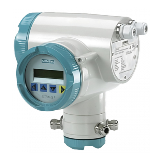
04.00 4.00.00 Design SITRANS FUS060 is an ultrasonic flow transmitter engineered for high performance and suitable for use with 1-path, 2-path, and 4-path flow sensors. The complete flowmeter consists of an ultrasonic flow sensor of the types SONO 3100, SONO 3300 or SONOKIT and the associated SITRANS FUS060 transmitter. - Page 18 Description 3.2 Design Figure 3-1 FUS060 SITRANS FUS060 with PROFIBUS PA Operating Instructions, 09/2021, A5E02225054-AD...
-
Page 19: Nameplate Layout
Interface for circuits with type of protection intrinsic safety Gas group IIC T6…T3 Temperature class (read manual) Protection level Gb for use in Zone 1 ⑧ Year of Manuf. Year of manufacture Figure 3-2 FUS060 identification nameplate example SITRANS FUS060 with PROFIBUS PA Operating Instructions, 09/2021, A5E02225054-AD... -
Page 20: Measuring Principle
The proportional flow factor K is determined by "WET" calibration or calculated by "AUTO" in case of manual programming of mechanical/geometrical pipe data (SONOKIT only). The transducer angle (θ), distance between sensors (L) and pipe dimension (D and D ) are shown in the figure below. SITRANS FUS060 with PROFIBUS PA Operating Instructions, 09/2021, A5E02225054-AD... -
Page 21: Profibus Communication
Furthermore, the automatic updating of plant documentation and plant optimization during ongoing operation is supported. SITRANS FUS060 with PROFIBUS PA Operating Instructions, 09/2021, A5E02225054-AD... - Page 22 These profiles define the minimum functional requirements and optional extensions. A device-internal "Device Management" supplies all necessary basic information for finding the profile parameters to the control system configuration tools. In this SITRANS FUS060 with PROFIBUS PA Operating Instructions, 09/2021, A5E02225054-AD...
- Page 23 Tekn_beskr/Profibuss/syspa_e.pdf)" for further information. The DP/PA coupler or DP/PA Link is supplied by a power supply unit with safety extra-low voltage (SELV). This power supply must have adequate reserves for bridging brief power failures. SITRANS FUS060 with PROFIBUS PA Operating Instructions, 09/2021, A5E02225054-AD...
- Page 24 5 mA even when a device is defective. Note Every device has its own address to distinguish between the connected process devices. The address setting is described in the Commissioning (Page 41). SITRANS FUS060 with PROFIBUS PA Operating Instructions, 09/2021, A5E02225054-AD...
- Page 25 3.5 PROFIBUS communication PROFIBUS PA interface The PROFIBUS PA variant of the SITRANS FUS060 differs from the 4 to 20 mA / HART version in the bus interface and the omission of the digital output 2. This means that the basic functions of the device including the operation and display remain basically the same.
- Page 26 The following functions on the standard device with 20 mA / HART interface are not available on the PROFIBUS version as they can generally be replaced indirectly by the PROFIBUS functions. • Analog output (4 to 20 mA) • HART communication • Digital output 2 (relay output) SITRANS FUS060 with PROFIBUS PA Operating Instructions, 09/2021, A5E02225054-AD...
-
Page 27: Installing/Mounting
Note Before starting the installation of the device please read the "PNO Guide PROFIBUS PA" for further information. This guide must be followed when installing it. SITRANS FUS060 with PROFIBUS PA Operating Instructions, 09/2021, A5E02225054-AD... -
Page 28: Transmitter Installation
Standard mounting plate Note The standard mounting plate is only suitable for wall mounting. Note The special wall-mounting bracket is not part of the standard delivery and must be ordered separately. SITRANS FUS060 with PROFIBUS PA Operating Instructions, 09/2021, A5E02225054-AD... - Page 29 2. Fasten the transmitter and assembly bracket to the wall Note The fastening brackets and nuts are not needed for wall mounting. Wall mounting with assembly bracket. Dimensions in mm (inch). SITRANS FUS060 with PROFIBUS PA Operating Instructions, 09/2021, A5E02225054-AD...
-
Page 30: Turning The Local Display
5. Pull out the unit, turn it to the desired position and push it back in. 6. Screw the lid back on and mount the lid catch. ① Fastening hooks Figure 4-2 Unlocking the fastening hooks on the local display SITRANS FUS060 with PROFIBUS PA Operating Instructions, 09/2021, A5E02225054-AD... -
Page 31: Connecting
The connection of the transducers on the sensors type SONO 3100 and SONOKIT (both with SONO 3200 transducers) or in the terminal housing of sensor type SONO 3300 is described in the separate sensor operating instructions. SITRANS FUS060 with PROFIBUS PA Operating Instructions, 09/2021, A5E02225054-AD... - Page 32 • Earth transmitter housing. • Cables used for connection must have diameters fitting the glands. • Use shielded cables for the outputs • Compare data on rating plate with local power supply. SITRANS FUS060 with PROFIBUS PA Operating Instructions, 09/2021, A5E02225054-AD...
-
Page 33: Wiring The Transducer Cables
3. Carefully press the cables into the cable glands until the "snap" function fixes the cable inside the connection module. Make sure the cables are mounted correctly by smoothly pulling the cable. SITRANS FUS060 with PROFIBUS PA Operating Instructions, 09/2021, A5E02225054-AD... - Page 34 7. After the installation, check and, if necessary, correct the cable length setting of the transmitter (see menu 7). Wiring 1-path systems ① For 1-path sensors exchange the two unused cable glands with the blind plugs. Figure 5-2 Wiring transducer cables, 1-path system. SITRANS FUS060 with PROFIBUS PA Operating Instructions, 09/2021, A5E02225054-AD...
-
Page 35: Wiring Output And Power Supply
1. Release the lid of the terminal box by turning the 3 mm hexagon socket screw 2. Unscrew the lid. 3. Push the power cable and signal cable through the cable glands up to the terminal block. SITRANS FUS060 with PROFIBUS PA Operating Instructions, 09/2021, A5E02225054-AD... - Page 36 8. Lay cables in a bend in front of the cable glands to prevent moisture getting into terminal block. 9. Screw the lid tightly on to the housing by using a tool. The sealing ring must be clean and undamaged. 10.Remount the lid lock. SITRANS FUS060 with PROFIBUS PA Operating Instructions, 09/2021, A5E02225054-AD...
-
Page 37: Wiring Profibus Pa
It is recommended to use shielded twin core cables for connecting PROFIBUS PA to the transmitter. Connection topologies PA supports LINE, DROP, STAR topology and a combination of the three. Figure 5-6 Electrical wiring SITRANS FUS060 with PROFIBUS PA Operating Instructions, 09/2021, A5E02225054-AD... - Page 38 Potential equalization A suitable potential equalizer must be provided to avoid potential differences between the individual plant parts and thus the risk of malfunctioning. Refer to EN 60364-4-41 & EN 60364-5-54. SITRANS FUS060 with PROFIBUS PA Operating Instructions, 09/2021, A5E02225054-AD...
- Page 39 • Make sure that the installation guidelines provided by the "Wiring & Installation Application Guide" on the PROFIBUS website are followed • Make sure the wiring requirements for the device are met. • Make sure that all connectors are properly tightened. SITRANS FUS060 with PROFIBUS PA Operating Instructions, 09/2021, A5E02225054-AD...
- Page 40 Connecting 5.3 Wiring PROFIBUS PA SITRANS FUS060 with PROFIBUS PA Operating Instructions, 09/2021, A5E02225054-AD...
-
Page 41: Commissioning
Error symptoms (Page 75). The failure signal is output at the output. Operating the device The device can be operated in the following ways: • Local display (LUI) • PROFIBUS PA • SIMATIC PDM (PC/laptop) SITRANS FUS060 with PROFIBUS PA Operating Instructions, 09/2021, A5E02225054-AD... -
Page 42: Commissioning Via Local User Interface
6.3.2 Operating via PROFIBUS communication The device can be operated via a PROFIBUS system based on the PROFIBUS PA communication protocol, see Figure 3-5 PROFIBUS PA architecture (Page 23). SITRANS FUS060 with PROFIBUS PA Operating Instructions, 09/2021, A5E02225054-AD... -
Page 43: Navigating The Menu
If the entered value is rejected, an error message briefly appears on the display followed by the previous setting. The value can be changed again. SITRANS FUS060 with PROFIBUS PA Operating Instructions, 09/2021, A5E02225054-AD... -
Page 44: Write Protection
(Page 105). The main functions are described in Functions (Page 51). 6.3.5 Operating examples The operating paths to be followed are represented in each diagram. The optical keypads to be actuated are specified and the individual operating steps numbered consecutively. SITRANS FUS060 with PROFIBUS PA Operating Instructions, 09/2021, A5E02225054-AD... - Page 45 Changing language from factory-set "English" to "German (Deutsch)" Example 2 – Setting of Bus Address Starting point is the multi-display. Figure 6-3 Changing the bus address from "126" to "100" (setting option: 0 to 126) SITRANS FUS060 with PROFIBUS PA Operating Instructions, 09/2021, A5E02225054-AD...
- Page 46 Please check the "Ident-Nr." Profile specific: 0x8159 (default setting) Manufacturer specific: 0x9741 Example 2 - Changing the flow value unit Figure 6-4 Changing the flow value unit from m /h to ft SITRANS FUS060 with PROFIBUS PA Operating Instructions, 09/2021, A5E02225054-AD...
- Page 47 4. 2. D i g Select the last position of the number with r a t e u l s e and terminate the input by pressing the operating element (Enter function). SITRANS FUS060 with PROFIBUS PA Operating Instructions, 09/2021, A5E02225054-AD...
-
Page 48: Commissioning Via Pdm
Supported SIMATIC PDM versions The EDD supporting this product is compatible with SIMATIC PDM v. 6.0 + SP5 + HF5 through 8.0 + SP2. 6.4.1 Configuration Figure 6-5 SIMATIC PDM (FUS060 HART example) SITRANS FUS060 with PROFIBUS PA Operating Instructions, 09/2021, A5E02225054-AD... - Page 49 2. Installing the device driver (download from EDD download (http:// support.automation.siemens.com/WW/view/en/24481552/133100)). 3. Adding the device to the SIMATIC PDM network. 4. Configuring the device. 5. Optimizing the system. 6. Checking the operation readiness. SITRANS FUS060 with PROFIBUS PA Operating Instructions, 09/2021, A5E02225054-AD...
- Page 50 Commissioning 6.4 Commissioning via PDM SITRANS FUS060 with PROFIBUS PA Operating Instructions, 09/2021, A5E02225054-AD...
-
Page 51: Functions
Set the backlight turn-off. At power-off this function is automatically reset to the default value Off. Off: At infrared key operation, the light turns on automatically and off again 10 minutes after last key action. SITRANS FUS060 with PROFIBUS PA Operating Instructions, 09/2021, A5E02225054-AD... - Page 52 Frequency and Current output (menus 1.7 and 1.8) The arithmetically calculated output values are displayed in the menu 1.7 Frequency (in Hz) and in menu 1.8 Current Output (in mA), irrespective of whether the output is used. SITRANS FUS060 with PROFIBUS PA Operating Instructions, 09/2021, A5E02225054-AD...
-
Page 53: Diagnostics (Menu 2)
After every reset or power off of the device, all error messages are available again, thus this menu setting is not stored. Device test (menu 2.3) The following test sub routines are available: SITRANS FUS060 with PROFIBUS PA Operating Instructions, 09/2021, A5E02225054-AD... -
Page 54: Measuring Functions (Menu 3)
• Time constant (damping) Note When switching between different units a rounding-off may need to be corrected manually. Density (menu 3.1.4) After entering units the display will automatically step into Density. SITRANS FUS060 with PROFIBUS PA Operating Instructions, 09/2021, A5E02225054-AD... - Page 55 % of full scale value (Max. vol. flow; menu 3.1.2). The setting range is 0 to 20 % of full scale value with a default value of 1 %. Example 1: Hysteresis = 0 % Digital output 1 = flow direction SITRANS FUS060 with PROFIBUS PA Operating Instructions, 09/2021, A5E02225054-AD...
- Page 56 The low flow cut-off suppression has no influence on the signaling of the flow direction. Low Flow Cut (menu 3.1.6) The residual flow is an absolute value in flow units and is not automatically converted when the scaling changes. SITRANS FUS060 with PROFIBUS PA Operating Instructions, 09/2021, A5E02225054-AD...
- Page 57 The flow display in % (menu 1.1.4) is also related to the output scale. Figure 7-1 Assignment between measured value SITRANS FUS060 with PROFIBUS PA Operating Instructions, 09/2021, A5E02225054-AD...
- Page 58 Set Totalizer (menus 3.4.3, 3.5.3, 3.6.3 and 1.3.4) "Stop+Reset":The selected totalizer is stopped and set to "0". The totalizer remains stopped and may have to be restarted. "Start": The selected totalizer is started. SITRANS FUS060 with PROFIBUS PA Operating Instructions, 09/2021, A5E02225054-AD...
-
Page 59: Device Outputs (Menu 4)
126. We recommend setting an address > 30 for SITRANS FUS060 as addresses below 30 are normally issued to masters. Each address on the PROFIBUS may only be issued once. - Page 60 In this parameter the master on the PROFIBUS sets the minimum waiting time (minimum station delay time of responder) which the SITRANS FUS060 PA slave has to observe before it answers a master telegram (unit: bit time = 32 μs (time for 1 bit at 31.25 kbit/s)). This parameter is read- only and has the default setting of 11 bits.
- Page 61 ("P/F too high") will appear. If the pulse/frequency error message appears, it is required to adjust the pulse settings (menus 4.2.3 and 4.2.4) or the full scale frequency (menu 4.2.5). SITRANS FUS060 with PROFIBUS PA Operating Instructions, 09/2021, A5E02225054-AD...
- Page 62 Pulse value (menu 4.2.3) There are two parameters to be set for the pulse output in this menu: • Unit The physical unit (unit/pulse). • Pulse rate Number of mass/volume units per pulse. SITRANS FUS060 with PROFIBUS PA Operating Instructions, 09/2021, A5E02225054-AD...
-
Page 63: Identification (Menu 5)
For texts longer than 16 characters the marks < and > in the most left and/or the most right position of the display indicate that there are further characters to the left and/or right of the displayed text section. These are displayed by actuating the keys. SITRANS FUS060 with PROFIBUS PA Operating Instructions, 09/2021, A5E02225054-AD... -
Page 64: Service (Menu 6)
This menu offers service and diagnostics parameters for maintenance purpose. Note Backlight settings (LCD lighting) Off: Light turns off 10 minutes after last key action. On: On for 1 hour after last key action. SITRANS FUS060 with PROFIBUS PA Operating Instructions, 09/2021, A5E02225054-AD... - Page 65 The values displayed in the individual menu depend on the respective application (medium). The following data are available: • Gain • Amplitudes • Trigger level • Error count % • Time of flight - up (TOF up) SITRANS FUS060 with PROFIBUS PA Operating Instructions, 09/2021, A5E02225054-AD...
- Page 66 Delta TOF (menu 6.5.7) The time of flight difference is the measured difference in ps: TOF up – TOF down. The typical value is 1000 ps for a flow velocity of 0 m/s. SITRANS FUS060 with PROFIBUS PA Operating Instructions, 09/2021, A5E02225054-AD...
-
Page 67: Sensor Parameters (Menu 7)
The calibration constants are based on the following SONOKIT sensor geometry measurement report data: • Pipe diameter • Length from transducer front to transducer front of every path • Displacement of each sound path from center of pipe SITRANS FUS060 with PROFIBUS PA Operating Instructions, 09/2021, A5E02225054-AD... - Page 68 The cable length is the total length of the signal cable in one sound path. The measuring unit of the cable length is meters. The tolerance is ±0.5 m. SITRANS FUS060 with PROFIBUS PA Operating Instructions, 09/2021, A5E02225054-AD...
- Page 69 Roughness (menu 7.1.3.2) Roughness is the value for the inner pipe surface and should only be changed for SONOKIT. The range of this value is 0.01 mm to 10.0 mm. The standard Siemens sensors have a roughness of approximately 0.4 mm.
- Page 70 In this menu the number of paths is set depending on the sensor design. The number of paths is preset from factory and can be changed to 1-path, 2-path, 3-path or 4-path. The number of paths should only be changed for SONOKIT. SITRANS FUS060 with PROFIBUS PA Operating Instructions, 09/2021, A5E02225054-AD...
-
Page 71: Service And Maintenance
• Reliability of power supply, lightning protection, and grounds WARNING Impermissible repair and maintenance of the device • Repair and maintenance must be carried out by Siemens authorized personnel only. Return procedure Enclose the bill of lading, return document and decontamination certificate in a clear plastic pouch and attach it firmly to the outside of the packaging. -
Page 72: Keying In Sensor Data
Note The pipe data are taken from the SONOKIT sensor geometry measurement report or from another sensor data sheet or calibration report. SITRANS FUS060 with PROFIBUS PA Operating Instructions, 09/2021, A5E02225054-AD... - Page 73 Based on the entered data the transmitter is capable of measuring and calculating the actual flow. The accuracy of the system at this stage is dependent on for example the entered accuracy of the geometry data. SITRANS FUS060 with PROFIBUS PA Operating Instructions, 09/2021, A5E02225054-AD...
- Page 74 Service and maintenance 8.3 Keying in sensor data SITRANS FUS060 with PROFIBUS PA Operating Instructions, 09/2021, A5E02225054-AD...
-
Page 75: Troubleshooting/Faqs
• Error counters (me‐ turbance is present. nus 6.5.4.X) are not equal to 0. SITRANS FUS060 with PROFIBUS PA Operating Instructions, 09/2021, A5E02225054-AD... - Page 76 Operation with infrared keys not Light interference Check that display is not dirty. possible Check that display lid is locked (PDM force control). Bright auxiliary tools may be of assis‐ tance. SITRANS FUS060 with PROFIBUS PA Operating Instructions, 09/2021, A5E02225054-AD...
-
Page 77: Application Information Guide
FUS060 nameplate System S/N FUS060 nameplate Order No. FUS060 nameplate Software version Menu 5.2.3 or FUS060 nameplate Device status, error message, frequen‐ Menu 2.1 cy, ... Flow Menu 1.4 Flow velocity [m/s] SITRANS FUS060 with PROFIBUS PA Operating Instructions, 09/2021, A5E02225054-AD... - Page 78 Menu 6.5.3 (0 ..255) Error count Menu 6.5.4 [%] (0 ..100) Time of flight up Menu 6.5.5 [ns] Time of flight down Menu 6.5.6 [ns] Delta TOF Menu 6.5.7 [ps] SITRANS FUS060 with PROFIBUS PA Operating Instructions, 09/2021, A5E02225054-AD...
-
Page 79: Technical Specifications
Only passive signals for digital output 1 Output function, configurable for Pulse output Adjustable pulse significance ≤ 5000 pulses/s Adjustable pulse width ³ 0.1 ms Frequency response fEND selectable up to 10 kHz SITRANS FUS060 with PROFIBUS PA Operating Instructions, 09/2021, A5E02225054-AD... - Page 80 * Typically depending on accuracy of installation measurement Table 10-4 Rated operating conditions Rated operating conditions Ambient temperature (transmitter and sensor) -20...+50 °C (-4...+122 °F) Storage temperature -25...+80 °C (-13...+176 °F) Enclosure rating IP65 / NEMA 4 SITRANS FUS060 with PROFIBUS PA Operating Instructions, 09/2021, A5E02225054-AD...
- Page 81 Ex version 19 to 30 V DC/ 21 to 26 V AC Power failure No effect for at least 1 period (> 20 ms) Power consumption Approx. 10 VA / 10 W SITRANS FUS060 with PROFIBUS PA Operating Instructions, 09/2021, A5E02225054-AD...
- Page 82 ½" NPT cable gland set for FUS060 (NPT) sensor connection, 4 pcs. M16 bush to ½" NPT and 4 pcs. ½" NPT gray PA plastic glands Order number A5E00853663 Cable cross section 5 … 9 mm (0.20" … 0.35") Ambient temperature -20 … +100 °C (-4 … +212 °F) Nominal torque 3.5 Nm SITRANS FUS060 with PROFIBUS PA Operating Instructions, 09/2021, A5E02225054-AD...
-
Page 83: Profibus Pa Cable Specifications
1900 m (6233 ft) 1200 m (3937 ft) * not specified Siemens provides a suitable cable for non-hazardous area with following order number - 6XV1 830-5BH10 Overall cable length The overall cable length is made up of the length of the main cable and the length of all spurs (>1 m/3.28 ft). - Page 84 13 to 14 15 to 18 19 to 24 25 to 32 Max. length per spur 120 m (393 ft) 90 m (295 ft) 60 m (196 ft) 30 m (98 ft) SITRANS FUS060 with PROFIBUS PA Operating Instructions, 09/2021, A5E02225054-AD...
-
Page 85: Dimension Drawings
Dimension drawings Figure 11-1 FUS060 with standard mounting bracket. Figure 11-2 FUS060 with the optional special mounting bracket. SITRANS FUS060 with PROFIBUS PA Operating Instructions, 09/2021, A5E02225054-AD... - Page 86 Dimension drawings SITRANS FUS060 with PROFIBUS PA Operating Instructions, 09/2021, A5E02225054-AD...
-
Page 87: Product Documentation And Support
– "Download as html5, only PC": Open or save the manual in the HTML5 view on your PC You can also find manuals with the Mobile app at Industry Online Support (https:// support.industry.siemens.com/cs/ww/en/sc/2067). Download the app to your mobile device and scan the device QR code. Product documentation by serial number Using the PIA Life Cycle Portal, you can access the serial number-specific product information including technical specifications, spare parts, calibration data, or factory certificates. -
Page 88: Technical Support
Additional information on our technical support can be found at Technical Support (http:// www.siemens.com/automation/csi/service). Service & support on the Internet In addition to our technical support, Siemens offers comprehensive online services at Service & Support (http://www.siemens.com/automation/serviceandsupport). Contact If you have further questions about the device, contact your local Siemens representative at Personal Contact (http://www.automation.siemens.com/partner). -
Page 89: Profibus Communication
PROFIBUS communication SITRANS FUS060 has a PROFIBUS PA connection compliant with IEC 1158 (synchronous transmission). The only possible baud rate is 31.25 kbits/s. The min TSDR (smallest station delay time, see chapter below) at startup is 11 bit times and can subsequently be changed using the Set_Prm service. -
Page 90: Acyclic Data Transmission
Acyclic accesses can be carried out by Master class 1 (C1 connection) or Master class 2 (C2 connection). SITRANS FUS060 PROFIBUS PA supports up to 4 simultaneous C2 connections. The approximately 400 parameters including address (slot and index), format, value range, start value and attributes are stored in an object list "Obj8159.rtf"... -
Page 91: Status Bytes
These components may adopt the following values in SITRANS F: Table B-4 Formats of the quality bits Profile Designation Meaning Measured value cannot be used uncertain Measured value uncertain good (not cascade) Measured value OK SITRANS FUS060 with PROFIBUS PA Operating Instructions, 09/2021, A5E02225054-AD... - Page 92 The measured value has exceeded the upper limit (alarm, warning or sensor limit) high limited The measured value has exceeded the upper limit value (alarm, warning or sensor limit) constant Measured value remains constant SITRANS FUS060 with PROFIBUS PA Operating Instructions, 09/2021, A5E02225054-AD...
- Page 93 O.K. good O.K. O.K. Note The status conditions have decreasing priority from top to bottom. If several status conditions are fulfilled, the current status with the highest priority will be signaled. SITRANS FUS060 with PROFIBUS PA Operating Instructions, 09/2021, A5E02225054-AD...
-
Page 94: Output Data (From Master To Slave)
The Diag_Flag is always set when the last 4 bytes of the diagnostic data (corresponds with the DIAGNOSIS parameter) have changed since the last message therefore also, for example, when the diagnostic messages disappear again so that the master register each change in the diagnostic data. SITRANS FUS060 with PROFIBUS PA Operating Instructions, 09/2021, A5E02225054-AD... - Page 95 PROFIBUS communication B.6 Diagnostics If a diagnostic message is active, the corresponding bit is set or reset. The following bits in the external diagnostic data are supported by SITRANS FUS060-PA all other bits always remain reset: Table B-10 Format of the diagnostic data, byte 4 Bit No.
-
Page 96: Write Protection
Parameter consistency between the device and control system is decisive for the correct interpretation of the cyclical measured values. During operation the local write protection (menu 6.2) or WRITE_LOCKING should therefore be enabled. SITRANS FUS060 with PROFIBUS PA Operating Instructions, 09/2021, A5E02225054-AD... -
Page 97: Device Data Base File (Gsd File)
For the configuration data this means that the first identifier always represents the flow, the second the sound velocity, ... , the last the quantity reverse. If you want to omit a measured value, set "Free Place" as the identifier. SITRANS FUS060 with PROFIBUS PA Operating Instructions, 09/2021, A5E02225054-AD... -
Page 98: Gsd Files
GSD files ;******************************************************************* GSD Datei für SITRANS FUS060, SIEMENS AG MLFB: 7ME3050-*AB20-1BA* Stand: 26.08.2015 Si028159.GSD ;*******************************************************************... - Page 99 If you don´t want to get the measuring value of a certain module from the ; device with the input data, use Free place for this module instead of another ; identifier. SITRANS FUS060 with PROFIBUS PA Operating Instructions, 09/2021, A5E02225054-AD...
- Page 100 0x42, 0x84, 0x08, 0x05 EndModule ;------------------------------------------------------------------- ; Sound velocity Modules ;------------------------------------------------------------------- Module = "Sound velocity (short)" 0x94 EndModule Module = "Sound velocity (long)" 0x42, 0x84, 0x08, 0x05 EndModule ;------------------------------------------------------------------- ; Quantity net Modules ;------------------------------------------------------------------- SITRANS FUS060 with PROFIBUS PA Operating Instructions, 09/2021, A5E02225054-AD...
- Page 101 SLOT(2) = "Sound velocity" 4 1,4,5 SLOT(3) = "Quantity net" 6 1,6,7 SLOT(4) = "Sound amplitude" 8 1,8,9 SLOT(5) = "Quantity forward" 10 1,10,11 SLOT(6) = "Quantity reverse" 12 1,12,13 EndSlotDefinition SITRANS FUS060 with PROFIBUS PA Operating Instructions, 09/2021, A5E02225054-AD...
-
Page 102: Fw Revision History
PROFIBUS module. GSD file Compatible FW versions Supported features Si08159.gsd 2.01.04 DPV0 and DPV1 Si08159.gsd 2.01.07 DPV0 and DPV1 3.00.00 DPV0 and DPV1 Si028159.gsd 4.00.00 DPV0 and DPV1 SITRANS FUS060 with PROFIBUS PA Operating Instructions, 09/2021, A5E02225054-AD... -
Page 103: Profibus Parameters
PROFIBUS parameters Parameter table The parameter lists can be found in the objects list on the internet at: Flowdocumentation (http:// www.siemens.com/flowdocumentation) SITRANS FUS060 with PROFIBUS PA Operating Instructions, 09/2021, A5E02225054-AD... - Page 104 PROFIBUS parameters C.1 Parameter table SITRANS FUS060 with PROFIBUS PA Operating Instructions, 09/2021, A5E02225054-AD...
-
Page 105: Hmi Menu Structure
HMI menu structure The graphic below only shows the main levels of the menu structure. Figure D-1 Menu structure (main menus; FW 4.00.00-15) SITRANS FUS060 with PROFIBUS PA Operating Instructions, 09/2021, A5E02225054-AD... -
Page 106: Menu Items (Fw Rev. 4.00.00)
Total. net Flow Write Total. net Total. forward Total. reverse Flow velocity Sound velocity US-Amplitude Frequency 1.1.4 Display Flow Select presentation Physical Unit Physical units % Write Diagram (Bar in %) SITRANS FUS060 with PROFIBUS PA Operating Instructions, 09/2021, A5E02225054-AD... -
Page 107: Menu 2 - Diagnostics
Menu 2 - Diagnostics Menu Device function, Description Factory setting Setting options Read code Parameters or write Device status Device status Error messages are shown "OK" Only read Read See table in chapter SITRANS FUS060 with PROFIBUS PA Operating Instructions, 09/2021, A5E02225054-AD... -
Page 108: Menu 3 - Measuring Functions
3.1.4 gal/min, gal/d, Mgal/d, ImpGal/s, Im‐ pGal/min, ImpGal/d, g/s, g/min, g/h, kg/s, kg/min, kg/d, Ton/ min, Ton/h, Ton/d, lb/s, lb/ min, lb/h, lb/d, STon/ min, STon/h, STon/d SITRANS FUS060 with PROFIBUS PA Operating Instructions, 09/2021, A5E02225054-AD... - Page 109 Write Lower range value < Upper range value 3.2.3 Limits 3.2.3.1 Lo alarm limit Lower alarm limit +200 m/s 200 to 2000 m/s Write Lower alarm limit < Upper alarm limit SITRANS FUS060 with PROFIBUS PA Operating Instructions, 09/2021, A5E02225054-AD...
- Page 110 Vallue for lower limit of alarms -1.000.000.000 -1.000.000.000 to 0 Write 3.5.3 Setting reverse Volume totalizer reset to "0" and No action No action Write "stop/start" Reset + stop Reset + start Forward - reverse volume SITRANS FUS060 with PROFIBUS PA Operating Instructions, 09/2021, A5E02225054-AD...
-
Page 111: Menu 4 - Device Outputs
Flow min/max Total forw. max Total rev. min Total net. min Total net max No function 4.2.2 Signal type Configure output: Passive-pos. Passive-pos Write Signal: passive only Passive-neg Logic: positive or negative SITRANS FUS060 with PROFIBUS PA Operating Instructions, 09/2021, A5E02225054-AD... -
Page 112: Menu 5 - Identification
Device ID (HART True identification in HART long ad‐ Factory set (0 to 15) Read adress) dress (not relevant for PROFIBUS com‐ Read only munication) SITRANS FUS060 with PROFIBUS PA Operating Instructions, 09/2021, A5E02225054-AD... -
Page 113: Menu 6 - Service
0 to 9999 Write Code 0: User parameter are not pro‐ tected. Code>0: User parameters are protected under menu 6. Service code Only for service in the Siemens facto‐ Write Reset Re-start of unit without change of pa‐ Cancel Cancel... - Page 114 TOF down 1 TIME OF FLIGHT (TOF) of first path Value in ns Read udowntream 6.5.6.2 TOF down 2 TIME OF FLIGHT (TOF) of second Value in ns Read path downstream SITRANS FUS060 with PROFIBUS PA Operating Instructions, 09/2021, A5E02225054-AD...
- Page 115 Running / Finished Only during no-flow process condi‐ tions! 6.6.4 Undo zero tr. Undo last zero trim After choice shows Write "Zero Trim OK" Trim parameter 6.7.1 Error Filter SITRANS FUS060 with PROFIBUS PA Operating Instructions, 09/2021, A5E02225054-AD...
-
Page 116: Menu 7 - Sensor Parameters
7.1.3.1. Engr.unit Unit selection (m or in) Write 7.1.3.1. Pipe diameter Inside diameter of pipe (m or in) Depending on selec‐ 0.01 to 4.0 m Write tion at ordering 7.1.3.2 Roughness SITRANS FUS060 with PROFIBUS PA Operating Instructions, 09/2021, A5E02225054-AD... - Page 117 100.0000000 transmitter, which is (value with 7 frac‐ Note: Only shown if WET is selected typically done to‐ tional digits) in menu 7.1.1 gether with the or‐ dered sensor SITRANS FUS060 with PROFIBUS PA Operating Instructions, 09/2021, A5E02225054-AD...
- Page 118 100.0000000 transmitter, which is (value with 7 frac‐ Note: Only shown if WET is selected typically done to‐ tional digits) in menu 7.1.1 gether with the or‐ dered sensor SITRANS FUS060 with PROFIBUS PA Operating Instructions, 09/2021, A5E02225054-AD...
- Page 119 100.0000000 transmitter, which is (value with 7 frac‐ Note: Only shown if WET is selected typically done to‐ tional digits) in menu 7.1.1 gether with the or‐ dered sensor SITRANS FUS060 with PROFIBUS PA Operating Instructions, 09/2021, A5E02225054-AD...
- Page 120 100.0000000 transmitter, which is (value with 7 frac‐ Note: Only shown if WET is selected typically done to‐ tional digits) in menu 7.1.1 gether with the or‐ dered sensor SITRANS FUS060 with PROFIBUS PA Operating Instructions, 09/2021, A5E02225054-AD...
- Page 121 Number of paths connected to the Depending on or‐ 1-track Write transmitter; dered system config‐ 2-tracks typical 1-track (SONO 3100, SONO‐ uration 3-tracks KIT-1) or 4-tracks 2-tracks (SONO 3100, SONO 3300, SONOKIT-2) SITRANS FUS060 with PROFIBUS PA Operating Instructions, 09/2021, A5E02225054-AD...
- Page 122 HMI menu structure D.1 Menu items (FW Rev. 4.00.00) SITRANS FUS060 with PROFIBUS PA Operating Instructions, 09/2021, A5E02225054-AD...
-
Page 123: Index
Bus termination, 38 EMC performance, 37 Maintenance, 71 Error symptoms, 75 Manuals, 87 Material compatibility, 11 Measuring principle, 20 Menu structure, 106 Flow factor, 20 Flow velocity, 20 Output data, 94 SITRANS FUS060 with PROFIBUS PA Operating Instructions, 09/2021, A5E02225054-AD... - Page 124 Status byte combinations, 93 Status bytes, 91 Support, 88 Support request, 88 Technical support, 88 partner, 88 personal contact, 88 Temperature specifications, 14 Totalizer mode "SET_TOT", 94 Transit time, 20 Warranty, 10 SITRANS FUS060 with PROFIBUS PA Operating Instructions, 09/2021, A5E02225054-AD...
Need help?
Do you have a question about the SITRANS FUS060 and is the answer not in the manual?
Questions and answers