Table of Contents
Advertisement
Advertisement
Table of Contents

Related Manuals for Hunter DSP700 Series


Summary of Contents for Hunter DSP700 Series
- Page 1 Rhein Tech Laboratories, Inc. Client: Hunter Engineering Co. 360 Herndon Parkway Model/HVIN: 45-1549 Suite 1400 Standards: FCC 15.247 Herndon, VA 20170 IDs: LS3-45-1549/2938A-451549 http://www.rheintech.com Report #: 2016038DXT Appendix K: Manual Please refer to the following pages.
- Page 2 OPERATION INSTRUCTIONS Form 6093-T, 07-10e DSP700 Series Wireless Wheel Alignment Sensors Copyright 2010-2016 Hunter Engineering Company...
-
Page 4: Table Of Contents
Precautions for Systems Equipped with XF Cordless Sensors ......5 1.5 Sensor Battery Packs ..................... 7 1.6 DSP700 Series Sensors Battery Pack Replacement Instructions ......9 1.7 DSP700 Series Sensors Hot Swap Battery Pack Replacement Instructions ..10 1.8 User Battery Replacement: ................... 10 1.9 Vehicle Preparation ....................11 1.10 Equipment Components and Controls .............. - Page 5 • Contents DSP700 Series Wireless Wheel Alignment Sensors...
-
Page 6: Getting Started
A calibrated set of DSP700 series sensors can be used with any Hunter aligner using ® WinAlign software version 11.1 or greater. A calibrated set of DSP700 series sensors can be used with a PA100 series aligner with ® Pro-Align software version 1.10.X or greater. -
Page 7: Care And Cleaning Of The Sensors
Use caution when jacking the vehicle up or down. Misusing this equipment can shorten the life of the equipment. To prevent accidents and/or damage to the sensors, use only Hunter recommended accessories. Remove the sensors from the wheels before moving the vehicle. When sensors are not in use, store and charge them on the sensor cabinet. -
Page 8: Xf Pod
Pod. Occasionally the XF Pod may receive interference from electronic devices in the area (microwaves). The DSP700 series sensors and XF Pod may be configured to use different radio frequencies to minimize interference. The XF system transceiver generates radio waves in the range of 2.4 GHz. Radio waves at these frequencies reflect off most objects, resulting in an indoor and outdoor range of approximately 100 feet (30 meters). - Page 9 Hereby, Hunter Engineering Company, declares that this Hunter 45-1281 low power transceiver is in compliance with the essential requirements and other relevant provisions of Directive 1999/5/EC. 6 • Getting Started...
-
Page 10: Sensor Battery Packs
Connect the charging wire harness, 38-1103-2, to the charging port(s) on the sensor(s). Any time battery packs are being charged, the charge indicator light on the sensor will be illuminated. Getting Started • 7 DSP700 Series Wireless Wheel Alignment Sensors... - Page 11 Extension Cables DSP700 series sensors are supplied with four 38-1106-2 extension cables. These extension cables can be used if battery power for the sensors is low. Simply connect one end of the extension cables to the charging cables on the aligner and the other end to the charging port on the sensor.
-
Page 12: Dsp700 Series Sensors Battery Pack Replacement Instructions
Yellow = battery running low and will require charge soon Red (with battery recharging icon) = requires charging The charging circuit has been “fine tuned” to work specifically with Hunter battery pack, part number 194-27-1. Substituting different batteries is not recommended. -
Page 13: Dsp700 Series Sensors Hot Swap Battery Pack Replacement Instructions
Instructions This procedure provides instructions for hot swapping the battery pack in DSP700 series sensors during an alignment procedure. Hot swapping the battery will recall/retain the information in the sensor if the alignment procedure is still in progress. If the sensor was compensated prior to swapping the battery, the sensor will indicate it by illuminating the middle compensation indicator while flashing the two outer compensation indicators. -
Page 14: Vehicle Preparation
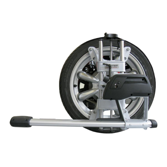
Check and adjust the tire pressure, inspect for unevenly worn or mismatched tires. Inspect all suspension and steering linkage components for wear or damage. A thorough inspection is important. 1.10 Equipment Components and Controls Getting Started • 11 DSP700 Series Wireless Wheel Alignment Sensors... - Page 15 DSP708 SENSORS 12 • Getting Started DSP700 Series Wireless Wheel Alignment Sensors...
-
Page 16: Mounting Sensors
If detached, attach the sensor to the wheel adaptor by inserting the sensor mounting shaft (at the rear of the sensor) into the sensor shaft mounting hole in the middle of the center casting. Mounting Sensors • 13 DSP700 Series Wireless Wheel Alignment Sensors... -
Page 17: Wheel Adaptor 175-321-1 With Ratchet Adaptor Locking Lever
9 o’clock, and lowering to re-engage. ADAPTOR LOCKING LEVER Re-position lever to 9 o’clock The adaptor locking lever in the 9 o’clock position eliminates possible contact with upper casting or sensor during alignments. 14 • Mounting Sensors DSP700 Series Wireless Wheel Alignment Sensors... - Page 18 Refer to figure below. Also refer to “2.2 Mounting Wheel Adaptors onto Wheels” for information for adjusting adaptor size. LOWERING THE UPPER CASTING CAN DAMAGE THE LEVER WHEN LOCATED IN THE WRONG POSITION Mounting Sensors • 15 DSP700 Series Wireless Wheel Alignment Sensors...
-
Page 19: Mounting Wheel Adaptors Onto Wheels
Do not allow the rim studs to slip on the wheel. Runout compensation and alignment accuracy will be adversely affected if the wheel adaptor is allowed to slip on the wheel. 16 • Mounting Sensors DSP700 Series Wireless Wheel Alignment Sensors... -
Page 20: Attaching To Inner Rim Lip
Do not allow the rim studs to slip on the wheel. Runout compensation and alignment accuracy will be adversely affected if the wheel adaptor is allowed to slip on the wheel. Mounting Sensors • 17 DSP700 Series Wireless Wheel Alignment Sensors... - Page 21 18 • Mounting Sensors DSP700 Series Wireless Wheel Alignment Sensors...
-
Page 22: Compensating Sensors
NOTE: It is recommended that the front wheels of front wheel drive vehicles be rotated in the forward direction to reduce disturbing the sensor on the opposite front wheel. Compensating Sensors • 19 DSP700 Series Wireless Wheel Alignment Sensors... - Page 23 For three-point compensation, if a previously compensated sensor should require re- compensation, pressing the sensor compensate button twice within four seconds will restart the compensation procedure and retake the first reading for that sensor at this position. 20 • Compensating Sensors DSP700 Series Wireless Wheel Alignment Sensors...
- Page 24 Compensating Sensors • 21 DSP700 Series Wireless Wheel Alignment Sensors...
-
Page 26: Operation Information
To balance sensors, loosen the screws securing the weight to the toe arm. Slide the weight in the proper direction to center the bubble in the level. Contact your local Hunter Service Representative if you need assistance with balancing adjustments.
Need help?
Do you have a question about the DSP700 Series and is the answer not in the manual?
Questions and answers