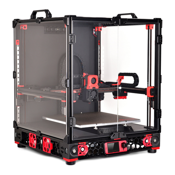
Summary of Contents for VORON 2.4
- Page 1 VORON 2.4 KIT 2 ∙ ALUMINIUM CAST HIGH PRECISION GROUND ∙ HEAT BED ∙ MAGNETIC SHEET WITH PEI...
- Page 2 Please do not become the first VORON fatality. There is no special Reddit flair for that. Please, read the entire manual before you start assembly. As you begin wrenching, please check our Discord channels for any tips and questions that may halt your progress.
-
Page 3: Deck Panel
DECK PANEL WWW.VORONDESIGN.COM M5 T-Nut NOTCH TO THE BACK FLIP PRINTER UPSIDE DOWN Deck Panel It’s easier working with gravity than against it. But make sure the rail carriages are secure before doing so. - Page 4 DECK PANEL WWW.VORONDESIGN.COM OPTIONAL The M5 washer are to be used if there is space left between the paneling and DIN bars. If this space were to remain, the paneling and DIN bars could move. DIN RAIL SLOTS If the slots in the rails do not line up with M5 Washer the t-nut you can shorten the DIN rails ALIGN T-NUTS WITH HOLES...
-
Page 5: Print Bed
PRINT BED WWW.VORONDESIGN.COM... - Page 6 OVERVIEW WWW.VORONDESIGN.COM Back Front WHICH SIDE IS WHICH? The top of the plate has mounting holes with bores that allow boltheads to sit flush/below the surface. The plate has additional tapped holes to secure the Protective Bottom Earth (PE) connection and a thermal fuse, those are on the back side of the plate.
- Page 7 If you have never done this before we recommend you watch the linked guide. Note: Slots can be made with a cutter to access the mounting holes in the aluminium plate. https://voron.link/rm6tpld...
- Page 8 HEATED BED WWW.VORONDESIGN.COM HEATER APPLICATION The heater is installed in the same fashion as the magnet. Centre it on the bottom side of the build plate and make sure to firmly press it on the build plate.
-
Page 9: Thermal Fuse
HEATED BED WWW.VORONDESIGN.COM THERMAL FUSE While not required to operate the printer, a thermal fuse M3x12 SHCS attached to the build plate adds an additional layer of protection against potentially dangerous malfunctions. The thermal fuse is wired in-line with the heater wires. Depending on the tapped holes in the plate you may Thermal Fuse need to use a shorter bolt. - Page 10 HEATED BED WWW.VORONDESIGN.COM M4x6 BHCS Ring Terminal PROTECTIVE EARTH (PE) 1mm²(AWG18) or larger...
- Page 11 HEATED BED WWW.VORONDESIGN.COM If the profiles do not already arrive smooth on the inside, drill through them from the Ø 4 mm drill bit. M4 Thumb Nuts M4 NUT FOR A M3 BOLT? We use the thumb nuts as spacers. You can replace them with different heat resistant spacers of the same length.
- Page 12 HEATED BED WWW.VORONDESIGN.COM M4x20 SHCS BED AND SPACER THICKNESS Depending on the combination of bed and spacer thickness you may need to use longer bolts to secure the bed. DON’T TIGHTEN Only tighten one bolt fully. Leave the remaining bolts slightly loose. This will allow for thermal expansion without putting additional stress on the plate.
- Page 13 HEATED BED WWW.VORONDESIGN.COM WIRE PASSTHROUGH Feed the bed related wires through the opening in the deck plate. Front VERIFY PLATE PLACEMENT The front edge of the print plate should sit 38mm behind the front edge of the frame.


Need help?
Do you have a question about the 2.4 and is the answer not in the manual?
Questions and answers