Table of Contents
Advertisement
Advertisement
Table of Contents

Related Manuals for SKF MKU Series


Summary of Contents for SKF MKU Series
- Page 1 EC Dir. 2006/42/EC Gear Pump Units of for partly completed machinery, with associated operating instructions Product Series MKU, MKF, MKL for oil and fluid grease for use in SKF MonoFlex single-line and oil+air centralized lubrication systems Version 04...
-
Page 2: Ec Declaration Of Incorporation
EC Declaration of Incorporation EC Declaration of Incorporation according to Machinery Directive 2006/42/EC, Annex II Part 1 B The manufacturer SKF Lubrication Systems Germany GmbH , Berlin Motzener Strasse 35/37, DE - 12277 Berlin hereby declares that the partly completed machinery:... - Page 3 Berlin Plant www.skf.com/lubrication. Motzener Strasse 35/37 12277 Berlin Germany Copyright / Integration of instructions © SKF Lubrication Systems Germany GmbH Tel. +49 (0)30 72002-0 All rights reserved Fax +49 (0)30 72002-111 www.skf.com/lubrication These instructions are protected by copy- right.
-
Page 4: Table Of Contents
Table of contents Table of contents Assembly instructions 2. Lubricants 4.3.2 MKU/MKF/MKL gear pump units with 3-liter plastic reservoir for oil Assembly instructions acc. to EC Dir. 2006/42/EC General information and luid grease for partly completed machinery, with associated Selection of lubricants operating instructions Approved lubricants 4.3.3... - Page 5 Table of contents Terminal diagrams for MKU/MKF, with pushbutton MKF, 3- or 6-liter reservoir, without control unit 4.7.11 Voltage design 24 VDC, 4.8.4 IG/IZ38 control unit, without pushbutton voltage design 230/115 VAC MKU, 2-liter reservoir, 4.7.1 Voltage design 230/115 VAC, 4.7.12 Voltage design 24 VDC, 4.8.5 IGZ36 control unit,...
- Page 6 Operating instructions associated with assembly instructions 1. Safety instructions Control unit designs with their 8. Maintenance basic settings General 2. Lubricants Lubrication systems Maintenance schedule 5.6.1 General Service 3. Delivery, returns, and storage 5.6.2 Total-loss lubrication systems Checking the delivery 5.6.3 Single-line systems with piston 9.
-
Page 7: Explanation Of Symbols And Signs
Explanation of symbols and signs Explanation of symbols and signs You will find these symbols, which warn of Read the instructions completely and follow Possible symbols specific dangers to persons, material assets, all operating instructions and the warning Meaning Symbol or the environment, next to all safety inst- and safety instructions. - Page 8 Explanation of symbols and signs Instructions placed on a unit, machine, or Abbreviations and conversion factors equipment, such as: Abbreviations regarding ounce o Rotation arrow approx. approximately pounds per square inch °C degrees Celsius horsepower o Fluid connection labels must be followed seconds pound and kept in fully legible condition.
-
Page 9: Safety Instructions
1. Safety instructions 1. Safety instructions 1.1 General safety instructions The operator must ensure that the assembly regulations for accident prevention and instructions/operating instructions are read environmental protection must be observed o All safety instructions and in-house inst- by all persons tasked with working on the and applied. -
Page 10: Qualiied Technical Personnel
Product training can also be performed by lations, and assembly conditions as a result SKF in exchange for costs incurred. of their training, experience, and instruction. They are qualified to carry out the required activities and in doing so recognize and avoid any potential hazards. -
Page 11: Electric Shock Hazard
1. Safety instructions 1.4 Electric shock hazard 1.5 System pressure or hydraulic 1.6 Operation pressure hazard The following must be observed while working WARNING WARNING on the product. o All information within this manual and Electric shock System pressure the information within the referenced Assembly, maintenance, and repair Hydraulic pressure documents... -
Page 12: Assembly/Maintenance/Malfunction/Decommissioning/Disposal
1.8 Intended use All relevant persons (e.g., operating personnel, o Ensure proper grounding of the product. Gear pump units of SKF series MKU, MKF, supervisors) must be informed of the activity o Drill required holes only on non-critical, and MKL are for supplying centralized lu- prior to the start of work. -
Page 13: Foreseeable Misuse
Unless specially indicated otherwise, gear Any usage of the product differing from The manufacturer shall not be held liable pump units of SKF series MKU, MKL, and the aforementioned conditions and stated for damage resulting from: MKF are not approved for use in potentially purpose is strictly prohibited. -
Page 14: Referenced Documents
1. Safety instructions 1.11 Referenced documents 1.12 Warning labels on the product In addition to this manual, the following documents must be observed by the The following information labels are affixed Positioning of warning labels, Fig 1 respective target group: to the product. -
Page 15: Residual Risks
1. Safety instructions 1.13 Residual risks Residual risk Remedy Life cycle: Assembly Electric shock due to defective power • Inspect the power lead/mains plug for damage before starting the product lead/mains plug People slipping due to floor contaminati- • Exercise caution when connecting the product’s hydraulic connections on with spilled/leaked lubricant •... - Page 16 1. Safety instructions Residual risk Remedy Life cycle: Malfunction, troubleshooting, maintenance, repair Electric shock due to defective power lead/ • Inspect the power lead/mains plug for damage before starting the product mains plug Electric shock from open electric motor or •...
-
Page 17: Lubricants
I part 2-5 of the CLP regulation of the lubricants are critically important in lubricant supplier. (EC 1272/2008) may be filled into SKF making these selections. When selecting a lubricant, the type of bea- centralized lubrication systems and compo-... -
Page 18: Approved Lubricants
NOTE NOTE The product described here can be operated using lubricants that meet the specifications If necessary, SKF Lubrication Systems can Only lubricants approved for the product in the technical data. Depending on the help customers to select suitable compo- may be used. -
Page 19: Lubricants And The Environment
2. Lubricants 2.4 Lubricants and the environment 2.5 Lubricant hazards NOTE WARNING NOTE Lubricants can contaminate soil and Lubricants Follow the safety instructions on the lubri- waterways. Lubricants must be used and Products must always be free of cant's safety data sheet. disposed of properly. -
Page 20: Overview
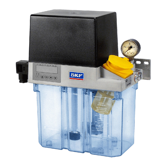
3. Overview 3. Overview 3.1 Description of designs MKU gear pump unit MKF gear pump unit MKL gear pump unit Units of product series MKU are suitable for Units of product series MKF are suitable for Units of product series MKL are designed for supplying oil with a viscosity range from supplying fluid greases of NLGI grades 000 oil+air centralized lubrication systems and... -
Page 21: Equipment Of A Mkx Gear Pump Unit
3. Overview 3.2 Equipment of a MKx gear pump unit Components of a MKx gear pump unit Equipment of a MKx gear pump unit, Fig. 2 Item Description 1 Gear pump unit without control unit (optionally with control unit with 3- or 6-liter lubricant reservoir) 2 Lubricant reservoir (2-/3-/or 6-liter) -
Page 22: Order Code
3. Overview 3.3 Order code for MKU gear pump units Order code – Product series MKx Electrical connection U = Oil lubricant Pressure gauge Delivery rate Pressure gauge 1 = 0.1 l/min • • • – 0 = Without pressure gauge 2 = 0.2 l/min –... - Page 23 3. Overview Voltage code 24 VDC, 320 VAC, 115 V AC Order example Voltage code Electrical connection MKU1-11AC10000+924 Control unit A, B Voltage Frequency Control unit o Gear pump unit for oil Monitoring X A B C D E C C o Delivery rate 0.1 l/min 24 V DC –...
-
Page 24: Mkf Gear Pump Units
3. Overview 3.4 Order code for MKF gear pump units Order code – Product series MKx Electrical connection F = Fluid grease lubricant Pressure gauge Delivery rate Pressure gauge 1 = 0.1 l/min • • 0 = Without pressure gauge 2 = 0.2 l/min –... - Page 25 3. Overview Voltage code 24 VDC, 320 VAC, 115 V AC Order example Electrical connection Voltage code MKF1-11AC10000+924 Control unit A, B Voltage Frequency Control unit o Gear pump unit for fluid grease Monitoring X A B C C C o Delivery rate 0.1 l/min 24 V DC –...
-
Page 26: Mkl Gear Pump Units
3. Overview 3.5 Order code for MKL gear pump units Order code – Product series MKx L = Oil + air system Voltage code 24 VDC, 320 VAC, 115 V AC Delivery rate Voltage code 1 = 0.1 l/min • •... -
Page 27: Assembly
NOTE These documents can be downloaded from The definition of qualified personnel and the homepage of SKF Lubrication Systems the prohibition against employing non- Observe the technical data (Chapter 4) Germany GmbH. qualified personnel are laid down in DIN and chapter 10 of the operating VDE 0105 and IEC 364. -
Page 28: Minimum Mounting Dimensions
4. Assembly WARNING The mounting position of the gear pump unit o The gear pump unit must be installed at is vertical as shown in this documentation. an adequate distance from sources of The ill level of the lubricant reservoir, heat. -
Page 29: Assembly Drawing With Minimum Installation Dimensions
4. Assembly 4.3 Assembly drawing with minimum installation dimensions 4.3.1 MKU/MKF gear pump units with 2-liter plastic reservoir for oil and fluid grease Recommended fastening hardware: o Hexagon head bolts (2x) acc. to ISO 4017-M8x25-8.8 o Washers (4x) acc. to ISO 7090- 8-200-HV o Hexagon nuts (2x) acc. -
Page 30: Mku/Mkf/Mkl Gear Pump Units With 3-Liter Plastic Reservoir For Oil And Luid Grease
4. Assembly 4.3.2 MKU/MKF/MKL gear pump units with 3-liter plastic reservoir for oil and fluid grease Recommended fastening hardware: o Hexagon head bolts (2x) acc. to ISO 4017-M6x25-8.8 o Washers (4x) acc. to ISO 7090- 6-200-HV o Hexagon nuts (2x) acc. to ISO 4032-M6-8 Tightening torque: 10 Nm Assembly holes... -
Page 31: Mku/Mkf/Mkl Gear Pump Units With 3-Liter Metal Reservoir For Oil And Luid Grease
4. Assembly 4.3.3 MKU/MKF/MKL gear pump units with 3-liter metal reservoir for oil and fluid grease Recommended fastening hardware: o Hexagon head bolts (2x) acc. to ISO 4017-M6x25-8.8 o Washers (4x) acc. to ISO 7090- 6-200-HV o Hexagon nuts (2x) acc. to ISO 4032-M6-8 Tightening torque: 25 Nm Assembly holes... -
Page 32: Mku/Mkf/Mkl Gear Pump Units With 6-Liter Plastic Reservoir For Oil And Luid Grease
4. Assembly 4.3.4 MKU/MKF/MKL gear pump units with 6-liter plastic reservoir for oil and fluid grease 11.5 27.5 % ¡ ¢ £ ¤ Recommended fastening hardware: o Hexagon head bolts (2x) acc. to ISO 4017-M8x25-8.8 o Washers (4x) acc. to ISO 7090- 8-200-HV o Hexagon nuts (2x) acc. -
Page 33: Example Hydraulic Connection
4. Assembly 4.3.5 Example hydraulic connection MKF 20 bar G1/4 G1/4 30 bar 0,5 bar 0,5 bar 30 bar M K F x - 1 x A X 0 x 0 0 0 + x x x M K F x - 1 x C C 1 x 0 0 0 + x x x without optional Pressure gauge with Pressure gauge without optional Fill level switch (NC) -
Page 34: Example Hydraulic Connection Mku
4. Assembly 4.3.6 Example hydraulic connection MKU 20 bar G1/4 G1/4 0,5 bar 30 bar 0,5 bar 30 bar M K U x - 1 x A X 0 x 0 0 0 + x x x M K U x - 1 x E C 1 x 0 0 0 + x x x without optional Pressure gauge with Pressure gauge without optional Fill level switch (NC) -
Page 35: Example Hydraulic Connection Mkl
4. Assembly 4.3.7 Example hydraulic connection MKL 20 bar G1/4 G1/4 30 bar 0,5 bar 0,5 bar 30 bar M K L x - 1 x F C 0 x 0 0 0 + x x x M K L x - 1 x F C 1 x 0 0 0 + x x x without optional Pressure gauge with Pressure gauge with Fill level switch (NC) -
Page 36: Attachment Of A Gear Pump Unit
4. Assembly 4.4 Attachment of a gear pump unit WARNING See Figures 3 to 6 • Tighten hexagon head screws with the • Drill assembly holes on the surface accor- following tightening torque Personal injury/property damage ding to the assembly drawing (assembly Torque M6 = 10 Nm Drill assembly holes in such a way... -
Page 37: Electrical Connection
4. Assembly 4.5 Electrical connection 4.5.1 Electric motor connection See Figure 10 Details regarding electrical connection of the Shielded cables must be used if electrical in- Consult the motor's rating plate for the motor to the power supply, especially terminal terference fields affect signal transmissions electrical characteristics of the motor. -
Page 38: Electric Motor Connection With Cable Socket And Circular Plug
4. Assembly 4.5.2 Electric motor connection with cable socket and circular plug Gear pump units (1) are driven by electric The wiring is connected in accordance motors. Depending on the model design, with the electrical circuit diagrams in See Figure 10 AC motors or DC motors are used. -
Page 39: Electric Motor Connection With Cable Glands
4. Assembly 4.5.3 Electric motor connection with cable glands Electrical connection, Fig.10 See Figure 10 The cover cap (1) is secured by two slotted screws (2). • Loosen but do not unscrew (!) the slotted Cable screws (2) from the cover cap (1) using a glands screwdriver. -
Page 40: Terminal Diagrams
4. Assembly 4.6 Terminal diagrams 4.6.1 Legend to the terminal diagrams Description and legend Legend: = Pump motor = Capacitor L1/S/N = Connection for operating voltage = Protective earth conductor = Fill level switch = Pressure switch = Pushbutton for interim lubrication = Indicator lamp (green) XS1 connector, XS2 connector... -
Page 41: Mku, 2-Liter Reservoir
4. Assembly 4.7 Terminal diagrams for MKU/MKF, without control unit 4.7.1 MKU, 2-liter reservoir, voltage design 230/115 VAC, without pushbutton MKU, 2-liter reservoir, voltage design 230 VAC/115 VAC, without pushbutton, Fig. 11 MKU1-11A _ _ 0000+428/+429 MKU1-11A _ _ 1000+428/+429 MKU1-11A _ _ 2000+428/+429 MKU1-11A _ _ 3000+428/+429 MKU1-11A _ _ 4000+428/+429... - Page 42 4. Assembly 4.7.2 MKU, 2-liter reservoir, voltage design 230/115 VAC, with pushbutton MKU, 2-liter reservoir, voltage design 230 VAC/115 VAC, with pushbutton, Fig. 12 MKU1-11B _ _ 0000+428/+429 MKU1-11B _ _ 1000+428/+429 MKU1-11B _ _ 2000+428/+429 MKU1-11B _ _ 3000+428/+429 MKU1-11B _ _ 4000+428/+429 230V/115V 50/60Hz 230V/115V 50/60Hz...
- Page 43 4. Assembly 4.7.3 MKU, 2-liter reservoir, voltage design 24 VDC, without pushbutton MKU, 2-liter reservoir, voltage design 24 VDC, without pushbutton, Fig. 13 MKU1-11A _ _ 0000+924 MKU1-11A _ _ 1000+924 MKU1-11A _ _ 2000+924 MKU1-11A _ _ 3000+924 MKU1-11A _ _ 4000+924 24V DC 24V DC 24V DC...
- Page 44 4. Assembly 4.7.4 MKU, 2-liter reservoir, voltage design 24 VDC, with pushbutton MKU, 2-liter reservoir, voltage design 24 VDC, with pushbutton, Fig. 14 MKU1-11B _ _ 0000+924 MKU1-11B _ _ 1000+924 MKU1-11B _ _ 2000+924 MKU1-11B _ _ 3000+924 MKU1-11B _ _ 4000+924 24V DC 24V DC 24V DC...
-
Page 45: Mkf, 2-Liter Reservoir
4. Assembly 4.7.5 MKF, 2-liter reservoir, voltage design 230/115 VAC, without pushbutton MKF, 2-liter reservoir, voltage design 230/115 VAC, without pushbutton, Fig. 15 MKF1-11A _ _ 0000+428/+429 MKF1-11A _ _ 1000+428/+429 MKF1-11A _ _ 2000+428/+429 MKF1-11A _ _ 3000+428/+429 MKF1-11A _ _ 4000+428/+429 230V/115V 50/60Hz 230V/115V 50/60Hz 230V/115V 50/60Hz... - Page 46 4. Assembly 4.7.6 MKF, 2-liter reservoir, voltage design 230/115 VAC, with pushbutton MKU, 2-liter reservoir, voltage design 230/115 VAC, with pushbutton, Fig. 16 MKF1-11B _ _ 0000+428/+429 MKF1-11B _ _ 1000+428/+429 MKF1-11B _ _ 2000+428/+429 MKF1-11B _ _ 3000+428/+429 MKF1-11B _ _ 4000+428/+429 230V/115V 50/60Hz 230V/115V 50/60Hz 230V/115V 50/60Hz...
- Page 47 4. Assembly 4.7.7 MKF, 2-liter reservoir, voltage design 24 V DC, without pushbutton MKF, 2-liter reservoir, voltage design 24 VDC, without pushbutton, Fig. 17 MKF1-11A _ _ 0000+924 MKF1-11A _ _ 1000+924 MKF1-11A _ _ 2000+924 MKF1-11A _ _ 3000+924 MKF1-11A _ _ 4000+924 24V DC 24V DC...
- Page 48 4. Assembly 4.7.8 MKF, 2-liter reservoir, voltage design 24 VDC, with pushbutton MKF, 2-liter reservoir, voltage design 24 VDC, with pushbutton, Fig. 18 MKF1-11B _ _ 0000+924 MKF1-11B _ _ 1000+924 MKF1-11B _ _ 2000+924 MKF1-11B _ _ 3000+924 MKF1-11B _ _ 4000+924 24V DC 24V DC 24V DC...
-
Page 49: Mku, 3- Or 6-Liter Reservoir
4. Assembly 4.7.9 MKU, 3- or 6-liter reservoir, voltage design 230/115 VAC, without pushbutton MKU, 3- or 6-liter reservoir, voltage design 230/115 VAC, without pushbutton, Fig. 19 MKU1 -12(3) A _ _ 0000+428/+429 MKU1 -12(3) A _ _ 1000+428/+429 MKU1 -12(3) A _ _ 2000+428/+429 MKU2(5)-12(3)(4)A _ _ 0000+428/+429 MKU2(5)-12(3)(4)A _ _ 1000+428/+429... - Page 50 4. Assembly 4.7.10 MKU, 3- or 6-liter reservoir, voltage design 230/115 VAC, with pushbutton MKU, 3- or 6-liter reservoir, voltage design 230/115 VAC, with pushbutton, Fig. 20 MKU1 -12(3) B _ _ 0000+428/+429 MKU1 -12(3) B _ _ 1000+428/+429 MKU1 -12(3) B _ _ 2000+428/+429 MKU2(5)-12(3)(4)B _ _ 0000+428/+429...
- Page 51 4. Assembly 4.7.11 MKU, 3- or 6-liter reservoir, voltage design 24 VDC, without pushbutton MKU, 3- or 6-liter reservoir, voltage design 24 VDC, without pushbutton, Fig. 21 MKU1-12(3) A _ _ 0000+924 MKU1-12(3) A _ _ 1000+924 MKU1-12(3) A _ _ 2000+924 MKU2-12(3)(4)A _ _ 0000+924 MKU2-12(3)(4)A _ _ 1000+924 MKU2-12(3)(4)A _ _ 2000+924...
- Page 52 4. Assembly 4.7.12 MKU, 3- or 6-liter reservoir, voltage design 24 VDC, with pushbutton MKU, 3- or 6-liter reservoir, voltage design 24 VDC, with pushbutton, Fig. 22 MKU1-12(3) B _ _ 0000+924 MKU1-12(3) B _ _ 1000+924 MKU1-12(3) B _ _ 2000+924 MKU2-12(3)(4)B _ _ 0000+924 MKU2-12(3)(4)B _ _ 1000+924 MKU2-12(3)(4)B _ _ 2000+924...
- Page 53 4. Assembly 4.7.13 MKF, 3- or 6-liter reservoir, voltage design 230/115 VAC, without pushbutton MKF, 3- or 6-liter reservoir, voltage design 230/115 VAC, without pushbutton, Fig. 23 MKF1-12 A _ _ 0000+428/+429 MKF1-12 A _ _ 1000+428(+429) MKF1-12 A _ _ 2000+428(+429) MKF2-12(4)A _ _ 0000+428/+429 MKF2-12(4)A _ _ 1000+428(+429) MKF2-12(4)A _ _ 2000+428(+429)
- Page 54 4. Assembly 4.7.14 MKF, 3- or 6-liter reservoir, voltage design 230/115 VAC, with pushbutton MKF, 3- or 6-liter reservoir, voltage design 230/115 VAC, with pushbutton, Fig. 24 MKF1-12 B _ _ 0000+428/+429 MKF1-12 B _ _ 1000+428/+429 MKF1-12 B _ _ 2000+428/+429 MKF2-12(4)B _ _ 0000+428/+429 MKF2-12(4)B _ _ 1000+428/+429 MKF2-12(4)B _ _ 2000+428/+429...
- Page 55 4. Assembly 4.7.15 MKF, 3- or 6-liter reservoir, voltage design 24 VDC, without pushbutton MKU, 3- or 6-liter reservoir, voltage design 24 VDC, without pushbutton, Fig. 25 MKF1-12 A _ _ 0000+924 MKF1-12 A _ _ 1000+924 MKF1-12 A _ _ 2000+924 MKF2-12(4)A _ _ 0000+924 MKF2-12(4)A _ _ 1000+924 MKF2-12(4)A _ _ 2000+924...
- Page 56 4. Assembly 4.7.16 MKF, 3- or 6-liter reservoir, voltage design 24 VDC, with pushbutton MKU, 3- or 6-liter reservoir, voltage design 24 VDC, with pushbutton, Fig. 26 MKF1-12 B _ _ 0000+924 MKF1-12 B _ _ 1000+924 MKF1-12 B _ _ 2000+924 MKF2-12(4)B _ _ 0000+924 MKF2-12(4)B _ _ 1000+924 MKF2-12(4)B _ _ 2000+924...
-
Page 57: Voltage Design 230/115 Vac
4. Assembly 4.8 Terminal diagrams for MKU/MKF/MKL, 3- or 6-liter reservoir, with control unit 4.8.1 MKU, IG/IZ38 control unit, voltage design 230/115 VAC MKU, IG/IZ38 control unit, voltage design 230/115 VAC, Fig. 27 MKU2/5-12/3/4C/D _ _ 0000+428/+429 MKU2/5-12/3/4C/D _ _ 1000+428/+429 230V/115V 50/60Hz 230V/115V 50/60Hz 115V... - Page 58 4. Assembly 4.8.2 MKU, IGZ36 control unit, voltage design 230/115 VAC 4.8.3 MKU, IGZ36 control unit, voltage design 24 VDC MKU, IGZ36 control unit, voltage design 230/115 VAC, Fig. 28 MKU, IGZ36 control unit, voltage design DC, Fig. 29 MKU2/5-12/3/4E _ _ 1000+924 MKU2/5-12/3/4E _ _ 1000+428/+429 Display Display...
- Page 59 4. Assembly 4.8.4 MKF, IG/IZ38 control unit, voltage design 230/115 VAC MKF, IG/IZ38 control unit, voltage design 230/115 VAC, Fig. 30 MKF2/5-12/4C/D _ _ 0000+428/+429 MKF2/5-12/4C/D _ _ 1000+428/+429 230V/115V 50/60Hz 230V/115V 50/60Hz 115V 115V 230V 230V 24VDC 24VDC IG/IZ38-30-I+471 IG/IZ38-30-I+471 SL1 SL2 SL1 SL2...
-
Page 60: Igz36 Control Unit, Voltage Design 230/115 Vac
4. Assembly 4.8.5 MKF, IGZ36 control unit, voltage design 230/115 VAC 4.8.6 MKF, IGZ36 control unit, voltage design 24 VDC MKF, IGZ36 control unit, voltage design 230/115 VAC, Fig. 31 MKF, IGZ36 control unit, voltage design DC, Fig. 32 MKF2/5-12/4E _ _ 1000+924 MKF2/5-12/4E _ _ 1000+428/+429 Display Display... -
Page 61: Ig54 Control Unit, Voltage Design 230/115 Vac
4. Assembly 4.8.7 MKL, IG54 control unit, voltage design 230/115 VAC 4.8.8 MKL, IG54 control unit, voltage design 24 VDC MKL, IG54 control unit, voltage design 230/115 VAC, Fig. 33 MKL, IG54 control unit, voltage design DC, Fig. 34 MKL2/5-12/3/4F _ _ 1000+428/+429 MKL2/5-12/3/4F _ _ 1000+924 Display Display... -
Page 62: Technical Connection Data
4. Assembly 4.9 Technical connection data Table 1 Reservoir capacity 2, 3, and 6 liters AC motor Rated frequency 50 Hz 60 Hz Weight empty Rated voltage 115/230 V 115/230 V Rated current 1.06/0.53 A 1.36/0.68 A Unit with 2-liter plastic reservoir 3.4 kg Rated output 60 W... -
Page 63: Lubrication Line Connection
10 to 36 V DC, ves). Output current (resistive load) ≤ 0.25 A SKF recommends the use of SKF plug Power consumption without output load < 10 mA (24 V), < 15 mA (36 V) connectors; see Chapter 12, Accessories. -
Page 64: Assembly Of The Main Lubrication Line With Tapered Sleeve Union
4. Assembly 4.11 Assembly of the main lubrication line with tapered sleeve union See Figure 35 • Deburr the connecting end of the main Lubrication line connection, Fig. 35 line (steel or plastic pipe) (1) • Remove the tapered sleeve (2) and socket union (3) from the connecting end (5) •... -
Page 65: Assembly Of The Lubrication Lines Using Plug Connectors
Both designs, for metal and plastic To remove the metal pipe (1), press the pipes, have a locking claw. The locking claw of the collet secures the pipe in the SKF plug collet (4) inward into the SKF plug connector, which prevents the pipe from connector. -
Page 66: System Criteria For Mkl Gear Pump Unit
Collet instructions for the oil+air lubrication system Collet First O-ring 2 when assembling and designing the system. First O-ring The assembly instructions for the SKF OLA oil+air system are 951-170-004-EN. Locking claw 5 Locking claw 5 Claw groove Mechanical Mechanical stop 3... -
Page 67: General Information On Lubrication Line Arrangement
4. Assembly 4.14 General information on lubrication line arrangement When arranging the main lubricant directional control valves, fittings, etc. must CAUTION lines and lubrication point lines, observe be carefully cleaned before assembly. No the following instructions in order to ensure seals in the lubrication line system should that the entire centralized lubrication system protrude inwards in a way that disrupts the... -
Page 68: Venting Centralized Lubrication System
4. Assembly 4.15 Venting a MKU/MKF/MKL centralized lubrication system The process of venting the centralized lubrication system can be facilitated by: Single-line centralized lubrication system, Fig. 38 Lubrication point o Opening the ends of the main pipes until lubricant without bubbles is discharged o Filling long pipe sections before connecting to the lubrication points •... -
Page 69: Note On The Rating Plate
Key data from rating plate, Fig. 39 The protective regulations of the low voltage directive 2014/35/EU are complied with according to annex I, no. 1.5.1 of machinery SKF Lubrication Systems Germany GmbH directive 2006/42/EC. Notes on the Pressure Equipment Directive 2014/68/EU... - Page 71 Operating instructions associated Gear Pump Units of with assembly instructions Product Series MKU, MKF, MKL for oil and fluid grease for use in SKF MonoFlex single-line and oil+air centralized lubrication systems...
-
Page 72: Safety Instructions
1. Safety instructions/ 2. Lubricants 1. Safety instructions 2. Lubricants 1.1 General information NOTE NOTE The operator of the product described here The lubricant notes listed in Chapter 2 must ensure that the operating instructions "Lubricants" of the assembly instructions are read and understood by all persons also apply without restriction to these responsible for assembly, operation, main-... -
Page 73: Delivery, Returns, And Storage
3. Delivery, returns, and storage 3. Delivery, returns, and storage 3.1 Checking the delivery 3.3.2 Electronic and electrical devices o Dry and dust-free surroundings, storage WARNING Immediately after receipt, the delivery must in well ventilated dry area be checked for completeness according o Storage time: max. -
Page 74: Assembly
4. Assembly 4. Assembly 5. Functional description 5.1 General 4.1 Information on assembly Gear pump units are reservoir units with The assembly procedure for the product electrically driven gear pumps that contain MKU gear pump unit, Fig. 1 is described in detail in the assembly all hydraulic and electrical components instructions (Chapter 4) associated with these required for the operation of a piston... -
Page 75: Structure Of A Gear Pump Unit
5. Functional description 5.2 Structure of a gear pump unit See Figure 1 theoretical reservoir capacity (rated capacity) mounted on. In the model design with a In the basic design, gear pump units con- can be used. control unit, the gear pump unit is equipped tain an electrically driven gear pump (1), a The pressure relief valve mounted in the with an electronic control unit that controls... - Page 76 Chapter 4 of the assembly The electrical circuit diagram of the gear instructions. pump unit is affixed inside the unit's cover The documentation can also be requested cap and can be accessed by removing the directly from SKF Lubrication Systems Germany GmbH.
-
Page 77: Gear Pump Unit Without Control Unit
5. Functional description 5.3 Gear pump unit without control unit Gear pump units without an integrated Consult the “Technical data” chapter for in- pressure drops too low. Ensure that a time electronic control unit are controlled by the formation on the operating mode. buffer is stored in the machine control unit control unit of the machine to which the With regard to monitoring pressure build-up... -
Page 78: Gear Pump Unit With Control Unit (Ig/Iz38, Igz36, Ig54)
5. Functional description 5.4 Gear pump unit with control unit (IG/IZ38, IGZ36, IG54) Gear pump units with a control unit contain The pump cycle time is 60 seconds and cannot unit's model design, a signal line for a programmable electronic control unit be changed. -
Page 79: Control Unit Designs With Their Basic Settings
5. Functional description 5.5 Control unit designs with their basic settings Control unit: IG38-30-I Operating instructions: 951-180-000-EN Description: The IG38-30-I is used as a pulse generator. Functions • Adjustable interval time IG38-30-I parameters, Table 1 • Interval time extension Designation Default Unit Adjusted via... - Page 80 5. Functional description Control unit: IGZ36-20-S6-I Operating instructions: 951-180-001-EN Description: The IGZ36-20-S6-I device can be used as a pulse generator (operating mode B) and a pulse counter (operating mode D). Functions • Adjustable interval time IGZ36-20-S6-I parameters, Table 3 • Adjustable pump delay time Designation Abbre- Default...
-
Page 81: Lubrication Systems
5. Functional description 5.6 Lubrication systems 5.6.1 General Gear pump units are generally used for required in order to ensure that the lubri- the system or due to the viscosity of the single-line systems with piston distributors. cation point receives adequate lubrication. lubricant (depending on the ambient tempe- Single-line systems with piston distributors Such systems are referred to as inter-... -
Page 82: Lubricating Cycle Sequence
5. Functional description 5.6.5 Lubricating cycle of prelubrication distributor ring line (use the second pressure port P) After the electric motor is switched on, the Prelubrication distributor system, Fig. 2 and the relief procedure in the centralized lubricant is drawn out of the lubricant lubrication system must be facilitated using reservoir by the gear pump and fed through Lubrication... -
Page 83: Lubricating Cycle Of Relubrication Distributor
5. Functional description 5.6.6 Lubricating cycle of relubrication distributor After the electric motor is switched on, the lubricant is drawn out of the lubricant Relubrication distributor system, Fig. 3 reservoir by the gear pump and fed through the lubricant line to the relubrication Pressure switch distributors via the pressure relief valve and Distributor... -
Page 84: Commissioning
6. Commissioning 6. Commissioning 6.1 General 6.2 Interim lubrication pushbutton NOTE The described product functions automati- The gear pump unit can optionally be equip- cally. The lubricant transport in the lubrication ped with a pushbutton (1) (DK) for manually Only fill using clean lubricant and an lines should, however, be subjected to regular triggering an interim lubrication. -
Page 85: Commissioning
6. Commissioning 6.3 Commissioning Before the product is commissioned, all • Check all connections for tight fit electrical and hydraulic connections must be • Check whether sufficient lubricant is inspected. present in the lubricant reservoir • Start the system The lubricant reservoir must be filled with clean lubricant without introducing bubbles. -
Page 86: Operation/Shutdown And Disposal
7. Operation/decommissioning and disposal 7. Operation/shutdown and disposal 7.1 Operation 7.2 Temporary shutdown NOTE The described product can be temporarily The product described here functions au- shut down by disconnecting the electrical tomatically. The lubricant transport in the and/or hydraulic supply connections. The Observe the instructions from the machine lubrication lines should, however, be subjected instructions in the "Assembly"... -
Page 87: Recommissioning
7.4 Shutdown and disposal The lubricant may only be fed without bubbles. If the product is to be shut down permanently, The product can also be returned to SKF The lubricant reservoir must be filled with observe the legal requirements for disposal Lubrication Systems Germany GmbH for clean lubricant. -
Page 88: Maintenance
(non-alkaline, non-soap). Only original SKF spare parts may be used. by qualified personnel authorized Unauthorized alterations and the use of For safety reasons, the product must be to do so by the operator. -
Page 89: Maintenance Schedule
8.3 Service If you encounter problems or have any questions, please contact our sales and ser- vice centers or our representatives abroad. A list with current addresses is available on the Internet at: www.skf.com/lubrication... -
Page 90: Malfunctions, Causes, And Remedies
SKF Service is capable of repairing them. WARNING NOTE Hot surface Only original SKF spare parts may be used. The hot surface of a motor may Unauthorized alterations to products and cause burns. Motor surfaces may the use of non-original spare parts and only be touched with appropriate accessories are prohibited. -
Page 91: Replacing A Defective Fuse (24 Vdc)
9. Malfunctions, causes, and remedies 9.2 Replacing a defective fuse (24 VDC) See Figure 5 • Replace the defective fuse (2) with a new Fuse replacement, Fig. 5 NOTE fuse of the same type The cause of the malfunction must be re- •... -
Page 92: Commissioning, Product, And System Malfunctions
9. Malfunctions, causes, and remedies 9.3 Commissioning, product, and system malfunctions Malfunction Cause Remedy • Check mains connection • Check mains plug/cable and connect properly if necessary o No operating voltage on motor • Check operating voltage on motor • Check fuse Motor fails to start •... - Page 93 Incorrect rotational direction of motor • If opening pressure is incorrect or if the pressure-regulating valve is damaged, replace the valve. Only use original SKF spare parts. • If contaminated, clean the pressure-regulating valve o Air in the main line •...
- Page 94 Pressure relief valve does not close • Clean or replace pressure relief valve. No pressure build up in Only use original SKF spare parts. the main line o Unsuitable lubricant (see technical • Remove lubricant from entire system and dispose of lubricant in data) the proper manner;...
-
Page 95: Technical Data
10. Technical data 10. Technical data Technical data Gear pump unit Unit MKU1(2)(5)-.. MKF1(2)-.. MKL1(2)(5)-.. General Delivery rate l/min 0.1 (0.2)(0.5) 0.1 (0.2) 0.1 (0.2)(0.5) Ambient temperature °C +10 to +40 +10 to +40 +10 to +40 Rated capacity of reservoir liter 2 (3) (6) 2 (3) (6) -
Page 96: Spare Parts
11. Spare parts 11. Spare parts Table 6 Reservoir capacity 2, 3, and 6 liters Weight empty Unit with 2-liter plastic reservoir 3.4 kg Unit with 3-liter plastic reservoir 4.2 kg Unit with 3-liter metal reservoir 5.0 kg Unit with 6-liter plastic reservoir 5.6 kg Delivery rate 0.1;... - Page 97 11. Spare parts Item Quantity Material number Designation Description 996-000-947 Pressure regulating valve 32 bar For oil 996-002-197 Pressure regulating valve 30 bar For luid grease MKF.U012 Pressure relief., cpl., for luid grease For luid grease MKU.U012 Pressure relief, cpl., for oil For oil MKF.U013 Pressure gauge for luid grease...
- Page 98 11. Spare parts Item Quantity Material number Designation Description WVN501-10.5x1.5 O-ring Seal for pressure switch MKF.U016 Level switch, cpl. For luid grease in 2- and 3-liter unit (NC contact) MKF.U116 Level switch, cpl. For luid grease in 6-liter unit (NC contact) MKU.U015 Fill level switch, cpl.
-
Page 99: Accessories
12. Accessories 12. Accessories Filling device Filling device with quick-action coupling, Fig. 6 Item Description Order No. Filling device, complete, with banjo fitting (Figure 7) 995-000-800 Coupling socket (for refill connection) 995-001-500 Sealing ring DIN 7603-A14x18-CU Hose socket for connection to coupling socket d ø13 857-760-007 d ø16... - Page 100 12. Accessories Filling device, see Fig. 8 Main line connections, Fig. 8 For plastic tubing Item Description Order No. Sealing ring 508-108 Connecting piece 406-054 Reinforcing socket 406-603 Socket union 406-612 Tapered sleeve 406-611 For steel tubing Socket union 406-002 Double tapered ring 406-001 Plug connector, straight...
- Page 101 12. Accessories Cable sockets Square connector and cable sockets, Fig. 10 Designation Order No. Weight Square connector per DIN EN 175301-803A 179-990-033 cable diameter 6–10 mm, 3-pin +PE, max. 1.5 mm² Cable sockets M12x1, 4-pin design, without LED Circular connector, straight, without cable 179-990-371 diameter 4–6 mm, 4-pin, max.
- Page 102 The Power of Knowledge Engineering Bearings Lubrication Over the course of more than a century, SKF has specialized in five fields of competence and acquired Seals and Bearing Systems a wide range of application expertise. We utilize this experience to provide innovative solutions to OEMs Units and other manufacturers in practically all industrial sectors worldwide.
Need help?
Do you have a question about the MKU Series and is the answer not in the manual?
Questions and answers